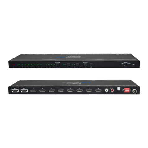
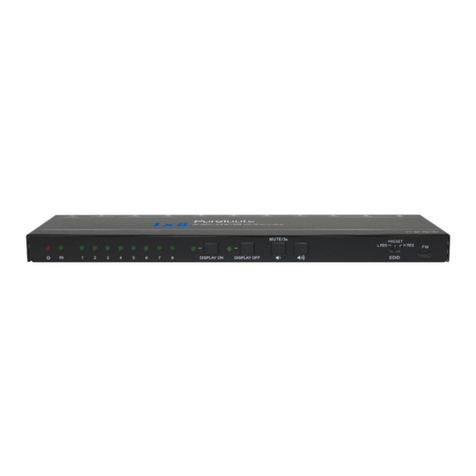
PureTools PT-SP-HD14DA User manual

User Manual
PT-SP-HD14DA
User Manual
HDMI Splitter 1x4 4K (60Hz 4:4:4) with Downscaling & Audio
De-embedding
Model PT-SP-HD14DA
Designed in Germany
© 2018 PureLink GmbH All rights reserved. V1.0

User Manual
PT-SP-HD14DA
Preface
Read this user manual carefully before using this product. Pictures shown in this
manual are for reference only. Different model layouts and specifications are subject
to the physical product.
This manual is for operation instructions only, not for any maintenance usage.
In the constant effort to improve our product, we reserve the right to make changes in
functions or parameters without prior notice or obligation.
Trademarks
Product model and logo are trademarks. Any other trademarks mentioned in this
manual are acknowledged as the properties of the trademark owner. No part of this
publication may be copied or reproduced without the prior written consent.
FCC Statement
This equipment generates, uses and can radiate radio frequency energy and, if not
installed and used in accordance with the instructions, may cause harmful
interference to radio communications. It has been tested and found to comply with
the limits for a Class B digital device, pursuant to part 15 of the FCC Rules. These
limits are designed to provide reasonable protection against harmful interference in
a commercial installation.
Operation of this equipment in a residential area is likely to cause interference, in
which case the user at their own expense will be required to take whatever measures
may be necessary to correct the interference.
Any changes or modifications not expressly approved by the manufacture would void
the user’s authority to operate the equipment.

User Manual
PT-SP-HD14DA
REACH | 1907/2006/EU
ROHS | 2011/65/EU
PureLink hereby declares that this product PureTools PT-SP-HD14DA complies with
Directives 1907/2006/EU und 2011/65/EU.
EMC / LVD (Electro Magnetic Compatibility / Low Voltage Directive)
PureLink GmbH hereby declares that this product PureTools PT-SP-HD14DA complies
with Directives 2014/30/EU and 2014/35/EU. The full text of the EU Declaration of
Conformity is available at the following Internet address:
http://www.purelink.de/ce/4251364718278_CE.pdf

User Manual
PT-SP-HD14DA
SAFETY PRECAUTIONS
To ensure the best from the product, please read all instructions carefully before
using the device. Save this manual for further reference.
Unpack the equipment carefully and save the original box and packing material
for possible future shipment
Follow basic safety precautions to reduce the risk of fire, electrical shock and
injury to persons.
Do not dismantle the housing or modify the module. It may result in electrical
shock or burn.
Using supplies or parts not meeting the products’ specifications may cause
damage, deterioration or malfunction.
Refer all servicing to qualified service personnel.
To prevent fire or shock hazard, do not expose the unit to rain, moisture or install
this product near water.
Do not put any heavy items on the extension cable in case of extrusion.
Do not remove the housing of the device as opening or removing housing may
expose you to dangerous voltage or other hazards.
Install the device in a place with fine ventilation to avoid damage caused by
overheat.
Keep the module away from liquids.
Spillage into the housing may result in fire, electrical shock, or equipment damage.
If an object or liquid falls or spills on to the housing, unplug the module
immediately.
Do not twist or pull by force ends of the optical cable. It can cause malfunction.
Do not use liquid or aerosol cleaners to clean this unit. Always unplug the power
to the device before cleaning.
Unplug the power cord when left unused for a long period of time.
Information on disposal for scrapped devices: do not burn or mix with general
household waste, please treat them as normal electrical wastes.
User Manual
PT-SP-HD14DA
Table of Content
1. Product Introduction ..................................................................................................................1
1.1 Features ..............................................................................................................................1
1.2 Packing List ........................................................................................................................2
2. Specification.................................................................................................................................3
3. Panel Description........................................................................................................................5
3.1 Front Panel.........................................................................................................................5
3.2 Rear Panel ..........................................................................................................................6
4. System Connection.....................................................................................................................7
4.1 Usage Precautions............................................................................................................7
4.2 System Diagram................................................................................................................7
5. DIP Switch Operation .................................................................................................................8
5.1 EDID Management............................................................................................................8
5.2 HDCP Mode ........................................................................................................................ 9
6. Video Resolution Down-scaling ........................................................................................... 10
7. Firmware Upgrade.................................................................................................................... 10
8. Panel Drawing........................................................................................................................... 11
9. Troubleshooting & Maintenance.......................................................................................... 12
10. After-Sales Service ................................................................................................................ 13

User Manual
PT-SP-HD14DA
1
1. Product Introduction
Thanks for choosing the one input to four output HDMI2.0 Splitter. The splitter
supports HDMI video resolution up to 4K@60Hz 4:4:4, 1080P 3D and multichannel
audio formats. Besides passing EDID information from the display, there are multiple
built-in EDID settings can be selected by the 4-pin DIP switch on the front panel. The
splitter can de-embed digital stereo audio to one analog RCA audio output and one
optical Toslink audio output to provide audio sources for existing audio systems.
The splitter supports 4K to1080P down-scaling up to 4 outputs. Moreover, the splitter
provides a Micro-USB port for convenient firmware upgrade.
1.1 Features
Splits a single HDMI input to four HDMI outputs.
Supports HDMI 2.0, 4Kx2K@60Hz 4:4:4, Dolby Vision.
18Gbps high bandwidth.
HDMI input supports HDCP 2.2 and the outputs support HDCP Active or HDCP
Passive mode.
Supports video resolution down-scaling, the 4K input can be automatically
degraded to 1080P output for compatibility with 1080P display.
Built-in signal equalizer, provides capability to use longer range HDMI cable.
Up to 6 types of built-in EDIDs can be selected by DIP Switch.
RCA and Toslink audio outputs for audio de-embedded.
Up to 6 units can be cascaded to distribute video signal to multiple video displays.
CEC pass-through.
Micro-USB port for convenient firmware upgrade.

User Manual
PT-SP-HD14DA
2
1.2 Packing List
1x HDMI 2.0 1x4 Splitter
2x Mounting Ears with 4 Screws
4x Plastic Cushions
1x Power Adapter (5V DC 1A)
1x User Manual
Note: Please contact your distributor immediately if any damage or defect in the
components is found.

User Manual
PT-SP-HD14DA
3
2. Specification
Video Input
Input
(1) HDMI
Input Connector
(1) Female type-A HDMI
HDMI Input Resolution
Up to 4Kx2K@60Hz 4:4:4
HDMI Standard
2.0
HDCP Version
2.2, 1.4 compliant
Video Output
Output
(4) HDMI
Output Connector
(4) Female type-A HDMI
HDMI Output Resolution
Up to 4Kx2K@60Hz 4:4:4
HDMI Standard
2.0
HDCP Version
2.2, 1.4 compliant
Audio
Output
(1) AUDIO OUT, (1) SPDIF OUT
Output Connector
(1) RCA connector (L+R), (1) Toslink connector
HDMI Audio Format
LPCM 7.1 audio, Dolby Atmos® , Dolby® TrueHD,
Dolby Digital® Plus, DTS: X™, and DTS-HD® Master
Audio™ pass-through
DP Audio Format
8 channels LPCM, up to 24bit 192Khz, AC3, DTS
Analog L/R audio Format
PCM
Toslink Audio Format
PCM, Dolby Digital, DTS, DTS-HD
Max Output Level
2.0Vrms ± 0.5dB. 2V = 16dB headroom above
-10dBV (316mV) nominal consumer line level signal

User Manual
PT-SP-HD14DA
4
Audio
THD+N
<0.05% (-80dB), 20Hz ~ 20KHz bandwidth, 1KHz
sine at 0dBFS level (or max level)
SNR
>80dB, 20Hz ~ 20KHz bandwidth
Crosstalk Isolation
>70dB, 10KHz sine at 0dBFS level (or max level
before clipping)
L-R Level Deviation
<0.3dB, 1KHz sine at 0dBFS level (or max level
before clipping)
Frequency Response
Deviation
<±0.5dB 20Hz ~ 20KHz
Output Load Capability
1KΩ and higher (supports 10x paralleled 10KΩ
loads)
Stereo Channel Separation
>70dB@1KHz
Control
Control Part
(1) EDID 4-pin DIP switch, (1) Micro-USB port
General
Bandwidth
18Gbps
Operation Temperature
-10 ~ +55℃
Storage Temperature
-25 ~ +70℃
Relative Humility
10% - 90%
Power Supply
Input:100V~240V AC; Output: 5V DC 1A
Power Consumption
4W(Max)
Dimension (W*H*D)
190mm x 20mm x 100mm
Net Weight
545g

User Manual
PT-SP-HD14DA
5
3. Panel Description
3.1 Front Panel
①Power LED: The LED illuminates red when power is applied.
②INPUT LED: The LED illuminates blue when there is an input signal present.
③OUT 1~OUT 4 LED: The LED illuminates blue when there is HDMI output on the
corresponding channel.
④EDID: 4-pin DIP switch for EDID setting.
⑤FW: Micro-USB port for firmware upgrade.
12345

User Manual
PT-SP-HD14DA
6
3.2 Rear Panel
①IN:Type-A female HDMI input port to connect HDMI source.
②OUT 1 ~ OUT 4: Four Type-A female HDMI output port to connect HDMI displays.
③AUDIO OUT: RCA connector for analog audio output.
④SPDIF OUT: Toslink connector for optical audio output.
⑤DC 5V: DC barrel port to connect a power adapter.
12345

User Manual
PT-SP-HD14DA
7
4. System Connection
4.1 Usage Precautions
Make sure all components and accessories included before installation.
System should be installed in a clean environment with proper temperature and
humidity.
All of the power switches, plugs, sockets, and power cords should be insulated
and safe.
All devices should be connected before power on.
4.2 System Diagram
The following diagram illustrates typical input and output connections that can be
utilized with the splitter:
4K Blu-ray 4K TV AVR
4K TV 4K TV 4K TV
HDMI:
AUDIO:

User Manual
PT-SP-HD14DA
8
5. DIP Switch Operation
5.1 EDID Management
The Extended Display Identification Data (EDID) is used by the source device to match
its video resolution with the connected display. By default, the source device obtains
its EDID from the first connected display. Meanwhile, since the displays with different
capabilities are connected to the splitter, the DIP switch on the front panel can be
used to set the EDID to a fixed value to ensure the compatibility in video resolution.
The switch represents “0” when in the lower (OFF) position, and it represents “1”
while putting the switch in the upper (ON) position.
Switch 1~3 are used for EDID setting. The DIP switch status and its corresponding
setting are shown at the back of the product.
1 2 3 4
EDID Setting
1080p DTS/Dolby
4K/30Hz LPCM
4K/60Hz LPCM
4K/60Hz DTS/Dolby
Default
1 2 3 4
ON
OFF 1
0ON
OFF
ON
OFF
1 2 3 Priority OUT 1 > 2 > 3 > 4
ON
OFF
1 2 3 Priority OUT 4 > 3 > 2 > 1
ON
OFF
1 2 3
ON
OFF
1 2 3
1080p LPCM
ON
OFF
1 2 3
ON
OFF
1 2 3
ON
OFF
1 2 3
ON
OFF
1 2 3
4K/30Hz DTS/Dolby

User Manual
PT-SP-HD14DA
9
Switch Status
Video Resolution
Audio Format
000
Obtains EDID from the first detected display starting at HDMI
output 1>2>3>4.
001
Obtains EDID from the first detected display starting at HDMI
output 4>3>2>1.
010
1080P
LPCM
011
1080P
DTS/Dolby
100
3840x2160@30Hz
LPCM
101
3840x2160@30Hz
DTS/Dolby
110
3840x2160@60Hz
LPCM
111
3840x2160@60Hz
DTS/Dolby
5.2 HDCP Mode
Put switch 4 on “ON” position to select HDCP Active mode, or to “OFF” for HDCP
Passive mode.
Switch Status
Mode
HDCP
OFF (0)
Passive
(Default)
Automatically follows the display’s HDCP version.
ON (1)
Active
Automatically removes the HDCP content of HDMI
output for broader video solution.

User Manual
PT-SP-HD14DA
10
6. Video Resolution Down-scaling
The product supports video resolution down-scaling, the 4K input can be
automatically degraded to 1080P output for compatibility with 1080P display, shown
in the below chart.
Input
Output
#
Resolution
Refresh
Color
Space
Downscale
1080P Specs
1
3840x2160
60
4:4:4
Support
1080P@60Hz 4:4:4
2
3840x2160
30
4:4:4
Support
1080P@30Hz 4:4:4
3
3840x2160
24
4:4:4
Support
1080P@24Hz 4:4:4
4
3840x2160
60
4:2:0
Support
1080P@60Hz 4:2:0
5
3840x2160
30
4:2:0
Support
1080P@30Hz 4:2:0
6
3840x2160
24
4:2:0
Support
1080P@24Hz 4:2:0
7
3840x2160
60
4:2:2
Not Support
N/A
8
3840x2160
30
4:2:2
Not Support
N/A
9
3840x2160
24
4:2:2
Not Support
N/A
7. Firmware Upgrade
Please follow the below steps to upgrade firmware by the Micro-USB port:
1) Connect the splitter to the PC with USB cable.
2) Power on the splitter, and then the PC will automatically detect a U-disk named of
“BOOTDISK”.
3) Double-click to open the U-disk, a file named of “READY.TXT” will be showed.
4) Copy the latest upgrade file (.bin) to the “BOOTDISK” U-disk directly.
5) If the filename “READY.TXT” automatically turns to “SUCCESS.TXT”, the firmware
was upgraded successfully. If the firmware upgrade failed, please check the file
(.bin) and then follow the above procedure to operate again.
6) Remove the USB cable after firmware upgrade.

User Manual
PT-SP-HD14DA
11
8. Panel Drawing
190.0mm
20.0mm
100.0mm
1x4Splitter
4K (60Hz 4:4:4) with Downscaling
& Audio De-embedding
PT-SP-HD14DA

User Manual
PT-SP-HD14DA
12
9. Troubleshooting & Maintenance
Problems
Potential Causes
Solutions
Colour losing or no
video signal output in
HDMI display.
The connecting cables
may not be connected
correctly or it may be
broken.
Check whether the cables
are connected correctly and
in working condition.
The display is not
compatible with the
present output resolution.
Make sure the resolution of
the display(s) is compatible
with the present resolution.
No HDMI signal output
in the splitter while
local HDMI input is in
normal working state.
The connecting cables
may not be connected
correctly or it may be
broken.
Check whether the cables
are connected correctly and
in working condition.
Splash screen in output
devices.
Poor quality of the
connecting cable.
Change for another cable of
good quality.
Static becomes stronger
when connecting the
video connectors.
Bad grounding.
Check the grounding and
make sure it is connected
well.
Note: If your problem still remaining after following the above troubleshooting steps,
please contact your local dealer or distributor for further assistance.

User Manual
PT-SP-HD14DA
13
10. After-Sales Service
If there appear some problems when running the product, please check and deal
with the problems referring to this user manual. Any transport costs are borne by
the users during the warranty.
1) Product Limited Warranty: The product will be free from defects in materials
and workmanship for two years (The purchase invoice shall prevail).
Proof of purchase in the form of a bill of sale or receipted invoice which is
evidence that the unit is within the Warranty period must be presented to obtain
warranty service.
2) What the warranty does not cover (servicing available for a fee):
Warranty expiration.
Factory applied serial number has been altered or removed from the product.
Damage, deterioration or malfunction caused by:
Normal wear and tear.
Use of supplies or parts not meeting our specifications.
No certificate or invoice as the proof of warranty.
The product model showed on the warranty card does not match with the
model of the product for repairing or had been altered.
Damage caused by force majeure.
Servicing not authorized by distributor.
Any other causes which does not relate to a product defect.
Delivery, installation or labor charges for installation or setup of the product.
3) Technical Support: For any questions or problems, contact your distributor or
reseller and tell them the respective product name and version, the detailed
failure situation as well as the formation of the cases.

User Manual
PT-SP-HD14DA

User Manual
PT-SP-HD14DA
Asking for Assistance
Technical Support:
Phone: +49 5971 800299 - 0
Fax: +49 5971 800299 –99
Technical Support Hours:
8:30 AM to 5:00 PM Monday thru Thursday
8:30 AM to 4:00 PM Friday
Write to:
PureLink GmbH
Von-Liebig-Straße 10
D - 48432 Rheine
www.purelink.de
Table of contents
Other PureTools Cables And Connectors manuals

PureTools
PureTools PT-SP-HD124DA User manual

PureTools
PureTools PT-SP-HD12D User manual

PureTools
PureTools PT-SP-HD28DA User manual

PureTools
PureTools PT-SP-HD12S User manual

PureTools
PureTools PT-SP-HD14D User manual

PureTools
PureTools PT-SP-HD18D User manual

PureTools
PureTools PT-SP-HD14BT User manual

PureTools
PureTools PT-SP-DP12 User manual