PureTools PT-PSW-41RS User manual

User Manual
PT-PSW-41RS
User Manual
Scaler Switcher Multiformat Scaling, 4K (60Hz 4:2:0), HDBaseT Out
Model PT-PSW-41RS
Designed in Germany
© 2017 PureLink GmbH All rights reserved. VersionV1.0

User Manual
PT-PSW-41RS
Preface
Read this user manual carefully before using this product. Pictures shown in this
manual are for reference only. Different model layouts and specifications are subject
to the physical product.
This manual is for operation instructions only, not for any maintenance usage.
In the constant effort to improve our product, we reserve the right to make changes in
functions or parameters without prior notice or obligation.
Trademarks
Product model and logo are trademarks. Any other trademarks mentioned in this
manual are acknowledged as the properties of the trademark owner. No part of this
publication may be copied or reproduced without the prior written consent.
FCC Statement
This equipment generates, uses and can radiate radio frequency energy and, if not
installed and used in accordance with the instructions, may cause harmful
interference to radio communications. It has been tested and found to comply with
the limits for a Class B digital device, pursuant to part 15 of the FCC Rules. These
limits are designed to provide reasonable protection against harmful interference in
a commercial installation.
Operation of this equipment in a residential area is likely to cause interference, in
which case the user at their own expense will be required to take whatever measures
may be necessary to correct the interference.
Any changes or modifications not expressly approved by the manufacture would void
the user’s authority to operate the equipment.

User Manual
PT-PSW-41RS
REACH | 1907/2006/EU
ROHS | 2011/65/EU
PureLink hereby declares that this product PureTools PT-PSW-41RS complies with
Directives 1907/2006/EU und 2011/65/EU.
EMC / LVD (Electro Magnetic Compatibility / Low Voltage Directive)
PureLink GmbH hereby declares that this product PureTools PT-PSW-41RS
complies with Directives 2014/30/EU and 2014/35/EU. The full text of the EU
Declaration of Conformity is available at the following Internet address:
http://www.purelink.de/ce/4251364706831_CE.pdf

User Manual
PT-PSW-41RS
SAFETY PRECAUTIONS
To insure the best from the product, please read all instructions carefully before
using the device. Save this manual for further reference.
Unpack the equipment carefully and save the original box and packing
material for possible future shipment
Follow basic safety precautions to reduce the risk of fire, electrical shock and
injury to persons.
Do not dismantle the housing or modify the module. It may result in electrical
shock or burn.
Using supplies or parts not meeting the products’ specifications may cause
damage, deterioration or malfunction.
Refer all servicing to qualified service personnel.
To prevent fire or shock hazard, do not expose the unit to rain, moisture or
install this product near water.
Do not put any heavy items on the extension cable in case of extrusion.
Do not remove the housing of the device as opening or removing housing may
expose you to dangerous voltage or other hazards.
Install the device in a place with fine ventilation to avoid damage caused by
overheat.
Keep the module away from liquids.
Spillage into the housing may result in fire, electrical shock, or equipment
damage. If an object or liquid falls or spills on to the housing, unplug the
module immediately.
Do not twist or pull by force ends of the optical cable. It can cause
malfunction.
Do not use liquid or aerosol cleaners to clean this unit. Always unplug the
power to the device before cleaning.
Unplug the power cord when left unused for a long period of time.
Information on disposal for scrapped devices: do not burn or mix with general
household waste, please treat them as normal electrical wastes.

User Manual
PT-PSW-41RS
Contents
1. Introduction..................................................................................................................................1
1.1 Introduction to PT-PSW-41RS .......................................................................................1
1.2 Feature................................................................................................................................ 1
1.3 Package List .......................................................................................................................2
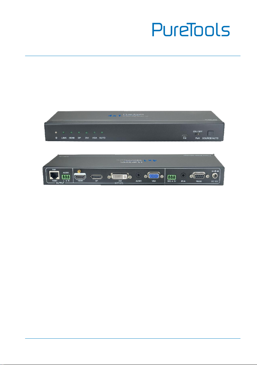
2. Product Appearance ...................................................................................................................3
2.1 Front Panel.........................................................................................................................3
2.2 Rear Panel ..........................................................................................................................4
3. System Connection.....................................................................................................................6
3.1 Usage Precaution..............................................................................................................6
3.2 System Diagram................................................................................................................7
3.3 Connection Procedure ....................................................................................................7
3.4 Application.........................................................................................................................8
4. System Operation........................................................................................................................9
4.1 Button Control...................................................................................................................9
4.1.1 Manual Switching .................................................................................................9
4.1.2 Auto Switching ......................................................................................................9
4.2 IR Control..........................................................................................................................10
4.2.1 Control the Scaler Switcher ............................................................................ 10
4.2.2 Control the Third-Party Device ...................................................................... 12
4.3 RS232 Control.................................................................................................................13
4.3.1 Control the Scaler Switcher ............................................................................ 13
4.3.2 RS232 Control Software .................................................................................. 13
4.3.3 RS232 Command ............................................................................................... 15
4.3.4 Control the Third-Party Device ...................................................................... 21
5. Specification.............................................................................................................................. 22
6. Panel Drawing........................................................................................................................... 24
7. Troubleshooting & Maintenance.......................................................................................... 25
8. After-Sales Service................................................................................................................... 26

User Manual
PT-PSW-41RS
1
1. Introduction
1.1 Introduction to PT-PSW-41RS
The PT-PSW-41RS with Extension is a compact mini scaler switcher with 4 video
inputs (1 HDMI, 1 DP, 1 DVI, and 1 VGA). As the VGA input supports VGA, YPbPr and
C-video, so the scaler switcher works with multiple video signals.
This product scales and switches any video signal to HDBaseT output (supports PoH
and connects to a Video Extender-HDBaseT Receiver, up to a maximum transmission
distance of 100 meters 4K ultra HD. With (1) IR IN and (1) RS232, the IR and RS232
signals can be transmitted between the Scaler Switcher and HDBaseT Receiver.
1.2 Feature
Compact 4x1 multi-format switcher with 4 video inputs 1 HDMI, 1 DP, 1 DVI, 1
VGA), 1 auxiliary audio input mirrored to the VGA/DVI input and 1 Dual-Mono
analog audio output .
Compliant with HDCP2.2.
Switches HDMI/DP/DVI/VGA input signals to HDBaseT output.
Scales to 6 different resolutions, DVI/VGA to HDBaseT output-Output resolution
selectable to assure preferred output. Support various output resolution, such as
1024×768, 1280×720, 1280×800, 1360×768, 1600x1200,1920×1080 (default,
can be chosen via commands or IR remote), 1920×1200.
Support HDBT2.0, transmit 4Kx2K signal up to 100m via single CAT5e/CAT6 cable.
Controlled via Front-panel button, IR and bi-directional RS232.
Controlled via Dry Contact.
Support advanced EDID Management.
Two input switching modes: auto-switching or manual-switching.
Intuitive indicator for power connect states, source selection, and switching mode
selection.
DVI video supports digital signal, VGA, YPbPr, C-video.

User Manual
PT-PSW-41RS
2
VGA video supports C-video, YPbPr and VGA.
Features a USB port for Firmware upgrades.
Compact design for easy operation, works in a variety of applications from
security monitoring, conference rooms, classrooms, control center and smart
homes.
Features off memory for reliable operation - input and output mapping is
automatically stored and recalled when the unit is powered on and off and in the
event of a power outage.
Supports hot plug.
1.3 Package List
1 x PT-PSW-41RS
2 x Mounting Ears
4 x Screws
4 x Plastic Cushions
1 x IR Receiver (with carrier wave)
1 x IR Remote (Cell battery is not included)
2 x 3-pin Phoenix Connectors
1 x Power Adapter (DC12V 2A)
1 x User Manual
Note: Confirm if the product and the accessories are all included, if not, please contact
with your dealers.

User Manual
PT-PSW-41RS
3
2. Product Appearance
2.1 Front Panel
①Indicators:
Power: Lights red when power is on, turns green in standby mode.
LINK: Lights green when the Scaler Switcher and HDBaseT Receiver are
successfully communicating via shielded category 5e or greater cabling
HDMI: HDMI Activity LED
DP: DisplayPort Activity LED
DVI: DVI Activity LED
VGA:.VGA Activity LED
AUTO: Auto-Switching Mode LED
②FW(USB Port):
Connects to a USB flash drive or other storage device to update the system
firmware. Please contact with our after-sales department for more details.
③PoH Mode Switcher
ON: Enable PoH function. The far-end HDBaseT Receiver are powered by the
Scaler Switcher 48VDC by PoH technology.
OFF: Disable PoH function.
LINK HDMI DP DVI VGA AUTO FW
ON / OFF
PoH SOURCE/AUTO
1234

User Manual
PT-PSW-41RS
4
④Source selection button / Switching mode selection button
Used as a video source selection button, press to select one source, press
again to select next source, switching sequentially between HDMI, DP, DVI and
VGA.
Used as a switching mode selection button, press and hold for 3 seconds or
more to enter auto-switching mode, the auto LED turn green and keep on.
Press and hold for 3 seconds or more again to enter manual-switching mode.
2.2 Rear Panel
①OUTPUTS:
HDBT/PoH: HDBaseT output, support PoH.
AUDIO: Dual-Mono analog audio output port, the audio comes from the input
audio corresponding to the selected video source.
②INPUTS
Video inputs: 1 HDMI, 1 DP, 1 DVI and 1 VGA source input ports. VGA port
support YPbPr, C-video, and VGA format. Factory default is VGA format.
Audio input: 1 3.5mm stereo audio source input port, provide external audio
input for DVI/VGA video signal, switched following the corresponding DVI/VGA
video input.
③SIG 5V
3-pin phoenix connector, connect with a reset button to be used as a video
source selection button.
PoH
DP
L R
AUDIO
OUTPUT HDMI INTPUTS SIG 5V
HDBT
123456

User Manual
PT-PSW-41RS
5
④IR IN
Connects with IR receiver (with carrier wave only), to receive IR signal send by
the IR remote to control this Scaler Switcher or far-end third-party device
connected to the HDBaseT Receiver.
⑤RS232
Serial control port, DB9 connector, connect with a control device (such as a
computer) to control the Scaler Switcher or other devices connected with
HDBaseT Receiver.
⑥DC 12V
Power port, connect with DC12V power adapter.

User Manual
PT-PSW-41RS
6
3. System Connection
3.1 Usage Precaution
Verify all components included with the product are present before
installation
System should be installed in a clean environment, preferably at ambient
temperature or within given working temperature range (see page 22 for
limits).
If the product will be permanently mounted to a surface, attach the included
mounting ears with the supplied screws.
If the products will be sitting on a shelf, attach the included Plastic cushions to
the bottom of the unit.
All of the power switches, plugs, sockets and power cords should be insulated
and safe.
Turn off power and disconnect the audio/video equipment by following the
manufacturer’s instructions.

User Manual
PT-PSW-41RS
7
3.2 System Diagram
3.3 Connection Procedure
Step1. Connect a HDMI source device to the HDMI Input port with HDMI signal cable.
Step2. Connect a DisplayPort source device to the DP Input port with DisplayPort
signal cable.
Step3. Connect a DVI source device to the DVI Input port with DVI signal cable.
Step4. Connect a VGA source device to the VGA Input port with VGA signal cable.
Step5. Connect the audio source device to the 3.5mm stereo audio source input port
with audio cable.
Step6. Connect an HDBaseT Receiver to the HDBT output port with twisted pair.
Step7. Connect a speaker, headphone, or amplifier to the Dual-Mono analog audio
output port.
Tx Rx
H
DP
L R
AUDIO
OUTPUT HDMI INTPUTS SIG 5V
HDMI:
DP:
DVI:
VGA:
Audio:
HDBT:
Control:
Apple TV Mac Book DVD Laptop
TV
Button
IR Receiver
Central Control System
Remote
Speakerr
PT-HDBT-702-RX

User Manual
PT-PSW-41RS
8
Step8. Connect a reset button to the SIG 5V port as needed, the button can be used as
a video source selector.
Step9. Connect the included IR Receiver to the IR IN port, the Switcher can be
controlled through the IR remote. While connect an IR Emitter to the IR OUT
port of HDBaseT port, the third party device connected to HDBaseT Receiver
also can be controlled via IR remote.
Step10. Connect control device (e.g. PC) to the RS232 port of the Scaler Switcher or
HDBaseT Receiver (bi-directional RS232 control, either end is available). The
Scaler Switcher can be control by sending RS232 commands via PC.
Step11. Connect DC12V power adaptor to the power port (HDBaseT Receiver is able
to get power from the Scaler Switcher with PoH function).
Notice: The Scaler Switcher supports unidirectional PoH, i.e., If the power adapter is
connecting with the Switcher, HDBaseT Receiver can be powered through HDBT port; but
when the power adapter is connecting with HDBaseT Receiver, the Switcher cannot be
powered by the HDBaseT Receiver.
3.4 Application
The Scaler Switcher has a good application in various occasions, such as computer
realm, monitoring, conference room, big screen displaying, television education,
command & control center and smart home etc.

User Manual
PT-PSW-41RS
9
4. System Operation
4.1 Button Control
Front panel buttons can be used for source selections, there are 4 sources for choose
in total, including HDMI, DP, DVI, VGA. Video signals support auto-switching and
manual switching (factory default).
4.1.1 Manual Switching
Press to SOURCE/AUTO button select one source, press again to select next source,
switching sequentially between HDMI, DP, DVI and VGA.
4.1.2 Auto Switching
Press and hold for SOURCE/AUTO button for 3 seconds or more to enter in
auto-switching mode. In this mode, the Scaler Switcher will follow these rules to
select input source automatically.
New input:
Once detecting a new input signal, the Scaler Switcher would switch to this new
signal automatically.
Rebooting device
The Scaler Switcher have the ability to save the last configuration before losing
power. If the last switching mode is auto-switching, once rebooted, the Scaler
Switcher will automatically enter auto-switching mode, and then detect all inputs
and memorize their connection status for future rebooting using. If the last
displayed signal is still available, the unit will output the signal. If not, the unit will
detect all the inputs signals with priority from HDMI to VGA. When detected the
first signal, it will transfer to output.

User Manual
PT-PSW-41RS
10
Signal removing
Once removing the current display signal, the Scaler Switcher will detect all input
signals with priority from HDMI to VGA. When detected the first signal, it will
transfer to output.
Notice:
In manual-switching mode, if you set the signal format of VGA/DVI input to
C-video or YPbPr, the system will not be able to enter Auto-switching mode.
In auto-switching mode, if the signal format of DVI input is C-video/YPbPr, the
Scaler Switcher can’t detect the DVI input, the command 50686% should be sent
via PC to convert C-video/YPbPr into digital signal format, and then the Scaler
Switcher will enter
In auto-switching mode, select input source via front panel button is not
available, but RS232 command and IR remote are able to switch mode.
4.2 IR Control
4.2.1 Control the Scaler Switcher
Firstly, connect IR Receiver to IR IN port;
Secondly, send command 50782% (IR Mode 2, factory default) via RS232
communication software, the Scaler Switcher can be controlled by using IR remote.
Here is the brief introduction for IR remote of this Scaler Switcher.

User Manual
PT-PSW-41RS
11
①Standby button
Enter/ exit standby mode
②Input channel selection buttons
Select video source via pressing corresponding
button (audio switched following the
corresponding DVI/VGA).
③Auto button
Enter/Exit auto-switching mode.
④Resolution selection buttons
Select output resolution for DVI/VGA input by
pressing corresponding button,including
1024×768, 1280×720, 1280×800, 1360×768,
1920×1080 (default,), 1920×1200.
Standby
HDMI DP
DVI AUTO VGA
INPUTS
4x1 Scaler Switcher
DVI/VGA
RESOLUTION
1024x768 1280x720 1280x800
1360x768 1920x1080 1920x1200
1
2
3
4

User Manual
PT-PSW-41RS
12
4.2.2 Control the Third-Party Device
Firstly, connect IR emitter to the IR OUT port of HDBaseT Receiver;
Secondly, send command 50781% (IR mode 1) via RS232 communication software,
the far-end display device (such as HDTV) can be controlled locally by using its IR
remote.
Tx Rx
DC 12 VIR IN IR OUT RS2 32SPD IF INHDM I OUTHDB TIN/ PoHETH ERNET
DVD
IR Remote
HDBaseT Receiver
HDTV
PoH
L R
AUDIO
OUTPUT
HDBT DPHDMI INTPUTS SIG 5V

User Manual
PT-PSW-41RS
13
4.3 RS232 Control
The Scaler Switcher and the far-end third-party RS232 device can be controlled by
sending RS232 commands via control PC. When to control a third-party RS232 device,
the baud rate of this device should be 2400, 4800, 9600, 19200, 38400, 57600 or
115200.
4.3.1 Control the Scaler Switcher
The Scaler Switcher can be control via RS232 commands, and the connection solution
show as below:
Control Scaler Switcher
4.3.2 RS232 Control Software
Installation Copy the control software file to the PC.
Uninstallation Delete all the control software files in corresponding file path.
Basic Settings:
First to connect the Scaler Switcher with all input devices and output devices needed,
then to connect it with a computer which is installed with RS232 control software.
Double-click the software icon to run this software.
PoH
L R
AUDIO
OUTPUT
HDBT DPHDMI INTPUTS SIG 5V
PC

User Manual
PT-PSW-41RS
14
Here we take the software CommWatch.exe as example. The icon is showed as below:
The interface of the control software is showed as below:
Please set the parameters of COM number, bound rate, data bit, stop bit and the
parity bit correctly, and then you are able to send command in Command Sending
Area.
Parameter Configuration area
Monitoring area, indicates if
the command sent works.
Command Sending area

User Manual
PT-PSW-41RS
15
4.3.3 RS232 Command
Communication protocol: RS232 Communication Protocol
Baud rate: 9600 Data bit: 8 Stop bit: 1 Parity bit: none
Switch Commands
Command
Function
Feedback Example
50701%
Switch to HDMI input
Switch to HDMI
50702%
Switch to DP input
Switch to DP
50703%
Switch to DVI input
Switch to DVI
50704%
Switch to VGA input
Switch to VGA
50680%
Convert into VGA signal format
for VGA input
Input VGA Set & Switch to VGA 1
50681%
Convert into YPbPr signal format
for VGA input
Input VGA Set & Switch to YPbPr 1
50682%
Convert into C-video signal
format for VGA input
Input VGA Set & Switch to AV 1
50683%
Convert into VGA signal format
for DVI input
Input DVI Set & Switch to VGA 2
50684%
Convert into YPbPr signal format
for DVI input
Input DVI Set & Switch to YPbPr 2
50685%
Convert into C-video signal
format for DVI input
Input DVI Set & Switch to AV 2
50686%
Convert into digital signal format
for DVI input
Input DVI Set & Switch to Digital
50770%
Enable auto-switching
Auto Switching
50771%
Disable auto-switching
Manual Switching
Table of contents
Other PureTools Media Converter manuals