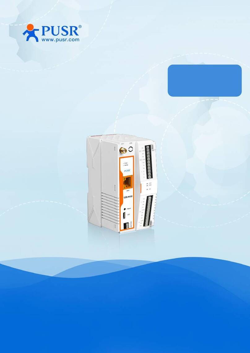
PUSR USR-M300 User manual

USR-M300 Start Guide
pusr.com
1
- 2 -
Content
1. Introduction ...............................................................................................................................................- 4 -
1.1. Overview...........................................................................................................................................- 4 -
1.2. Features............................................................................................................................................- 4 -
2. Get Started.................................................................................................................................................- 5 -
2.1. Hardware connection........................................................................................................................- 5 -
2.2. Login Gateway ..................................................................................................................................- 5 -
2.3. Brief introduction of the webpage .....................................................................................................- 6 -
3. Overview Information.................................................................................................................................- 7 -
4. Network .....................................................................................................................................................- 7 -
4.1. Network switching.............................................................................................................................- 7 -
4.2. Cellular .............................................................................................................................................- 8 -
4.3. Ethernet Port.....................................................................................................................................- 8 -
4.4. WAN Interface...................................................................................................................................- 9 -
4.5. LAN Interface ....................................................................................................................................- 9 -
4.6. Routing...........................................................................................................................................- 10 -
5. Edge Computing ......................................................................................................................................- 10 -
5.1. Edge Mode...................................................................................................................................... - 10 -
5.2. Preset Extension IO..........................................................................................................................- 11 -
5.3. IO Module .......................................................................................................................................- 12 -
5.3.1. DI Interface ............................................................................................................................- 12 -
5.3.2. Status of IO modules ..............................................................................................................- 14 -
5.4. Data Point.......................................................................................................................................- 14 -
5.5. Protocol .......................................................................................................................................... - 17 -
5.6. Edge Gateway.................................................................................................................................- 20 -
5.6.1. Serial Port .............................................................................................................................. - 20 -
5.6.2. Communication......................................................................................................................- 21 -
5.6.3. Data Query/Control................................................................................................................ - 21 -
5.6.4. Data Reporting.......................................................................................................................- 24 -
5.6.5. Linkage Control...................................................................................................................... - 26 -
6. System Management................................................................................................................................- 30 -
6.1. System Time....................................................................................................................................- 30 -

USR-M300 Start Guide
pusr.com
1
- 3 -
6.2. Log .................................................................................................................................................- 31 -
6.3. System............................................................................................................................................ - 31 -
6.3.1. Configuration Management....................................................................................................- 31 -
6.3.2. Firmware Upgrade.................................................................................................................- 32 -
6.3.3. User Management..................................................................................................................- 33 -
6.3.4. Reboot...................................................................................................................................- 33 -
6.4. PUSR Cloud Service .........................................................................................................................- 33 -
6.5. Location..........................................................................................................................................- 33 -
7. Contact Us................................................................................................................................................- 33 -
8. Disclaimer................................................................................................................................................- 33 -

USR-M300 Start Guide
pusr.com
1
- 4 -
1. Introduction
1.1. Overview
USR-M300 is a high-performance and scalable edge IOT gateway. This device integrates edge collection,
data calculation, data reading and writing, active reporting, linkage control, IO collection and control and other
functions. The collection protocol includes standard Modbus protocol and a variety of common PLC protocols, as
well as industry-specific protocols. At the same time, the product also has routing and VPN as well as graphical
programming functions to ensure data transmission security. Using graphical programming, users can develop
independently to achieve the required functions.
USR-M300 is embedded in Linux kernel, with a main frequency of up to 1.2Ghz. It can access the Internet via
Ethernet port, ADSL and LTE cat4 cellular network to achieve easy network deployment.
It is widely used in various industrial intelligent solutions such as industrial robot, smart factories, smart
agriculture, smart water management system etc.
1.2. Features
•Dual-core professor with ultra-high performance, the main frequency is up to 1.2Ghz, providing high-
performance processing resources for edge computing.
•Supports Python development, for developing user custom applications.
•Supports graphical programming to facilitate user development.
•LTE 4G and Ethernet network serve as backups for each other to ensure stable network transmission
without downtime.
•Integrated 1*WAN/LAN and 1*LAN Ethernet port, VPN and firewall protection to ensure safe data
transmission.
•Integrated 2 serial ports: 1*RS232/485, 1*RS485, which can transform traditional serial devices into IOT
devices.
•Comes with IO interface: 2*DI, 2*DO, 2*AI, flexible expandable IO module is supported.
•Powerful edge gateway function: supports edge collection, edge computing, group reporting, and
supports real-time collection of up to 2000 points.
•Supports major industrial protocols including Modbus TCP/RTU, PLC protocols and OPC UA Server.
•Support 2 socket channels, each channel supports TCP(SS)/UDP, MQTT(S) protocols.
•Cloud support: MQTT via AWS IOT, Alibaba Cloud, and PUSR Cloud.

USR-M300 Start Guide
pusr.com
1
- 5 -
2. Get Started
2.1. Hardware connection
Preparation:
Power adapter 12V/1A * 1
Network cable * 1
The hardware connection diagram is like the following:
2.2. Login Gateway
Power on the USR-M300, connect PC to M300 via LAN port, users can login the gateway via Chrome or the

USR-M300 Start Guide
pusr.com
1
- 6 -
other browser. The default network parameters are shown in the following table:
Table 1. Default network parameters
Parameter
Default value
LAN IP
192.168.1.1
Username
admin
Password
admin
Open the browser, enter 192.168.1.1 in the URL blank, and press Enter, it will navigate to the following webpage.
After entering the login password, clicking login, the web page will show configuration page of USR-M300.
Figure 1. Login webpage
2.3. Brief introduction of the webpage
There are several tabs on the top of the webpage, users can set parameters of USR-M300 on the tab pages.
➢Overview:On this page, users can quickly learn about the running status of the gateway, like system
information, device status, cellular information and etc.
➢Network: In this interface, there are many categories related to network connection. Users can set
parameters such as WAN port, LAN port and cellular network.
➢Edge Computing: With this functionality, the M300 gateway serves as host and actively sends the
polling acquisition command to periodically obtain the point data of the serial and Ethernet devices

USR-M300 Start Guide
pusr.com
1
- 7 -
and the data collected by the I/O interface.
➢System Management: In this webpage, users can check the log information, and set the system time
and so on.
➢Python Application: With this functionality, users can deploy Python applications.
3. Overview Information
In this page, it includes system information, device status, cellular information, flow usage monitoring and
performance of processor chipset.
Figure 2. Status webpage
4. Network
4.1. Network switching
On this page, users can select the Internet connectivity priority, and can also set the information of PING
detection.

USR-M300 Start Guide
pusr.com
1
- 8 -
4.2. Cellular
On this page, users can check the cellular information like the signal strength, IP address and so on. The APN
information can be set in this page also.
4.3. Ethernet Port
On this page, users can change the work mode of Ethernet Port1. This port is WAN mode by default. And it
can be changed to LAN mode. Then the users can get 2 Ethernet ports.

USR-M300 Start Guide
pusr.com
1
- 9 -
4.4. WAN Interface
User can set the parameters of WAN port like network mode, DNS mode and MTU.
4.5. LAN Interface
Users can set the basic information of LAN port like IP address, netmask and DHCP service. When the M300
enables the DHCP service, it can assign IP address to the terminal device connected to M300 via LAN port.

USR-M300 Start Guide
pusr.com
1
- 10 -
4.6. Routing
On this page, users can check the routing table and add needed static routing to USR-M300.
5. Edge Computing
5.1. Edge Mode
The edge mode is edge gateway by default. User can change the mode to Graphical Programming mode.
The Graphical Programming is based on Node RED, in this mode, user can develop the application about the
edge computing that they need.

USR-M300 Start Guide
pusr.com
1
- 11 -
Note: This setting needs to reboot the M300 gateway. Waiting another 2 minutes after the M300 starting,
then the Graphical Design page can be opened.
5.2. Preset Extension IO
As we all know, the M300 can work with extendable IO module to extend the IO numbers. If the extendable IO
modules are connected to M300, users need to preset the IO modules on webpage. The IO modules sequence
should be kept the same with the actual hardware sequence.
If the sequence on webpage is different from the hardware sequence of extendable IO modules, the work
indicators on M300 will fast blink, and the work indicators on IO extendable modules will blink 4 times/s, then

USR-M300 Start Guide
pusr.com
1
- 12 -
keep off for 2s.
5.3. IO Module
There are 2 parts in this function, the detail information and the status of IO modules.
5.3.1. DI Interface
On this page, users can check the settings of digital input interfaces, and can also set the work mode of DI
interfaces.
DI01: It means the first DI interface of USR-M300
DI22: It means the second DI input of the second extendable IO module.
DI27: It means the seventh DI input of the second extendable IO module.

USR-M300 Start Guide
pusr.com
1
- 13 -
The default DI mode is Digital Input, users can click “Edit” to modify the settings.
There is another function can be set on this page: Restart Hold of DO. This function is closed by default.
If the Restart Hold function is enabled, when we restart the M300, the DO will remain in the state before the
power outage.

USR-M300 Start Guide
pusr.com
1
- 14 -
5.3.2. Status of IO modules
On this page, users can check the status of IO interface. And can also control the DO interface. Click the DO
button, the indicators of DO will turn on or turn off.
5.4. Data Point
Data Point Table is the core database of the edge computing gateway. The data and data-related
information used by the edge gateway for acquisition, reporting, data reading and writing, protocol conversion
and linkage control are all obtained from this point table. Therefore, during use, it is very important to add the
data point table correctly and in detail.

USR-M300 Start Guide
pusr.com
1
- 15 -
The data point table contains two main elements: slaves and data points. Up to 20 slaves can be added, IO
slaves and virtual slaves are fixed. The remaining 18 Slaves can be added as needed. Corresponding data points
can be added to each slave. Except for the virtual slave, the total number of data points of all other slaves is up
to 2000. The data points of each slave are actively polled and collected from the corresponding interface
according to the protocol specified when adding the slave, and the collected data is correspondingly stored in
the virtual register in the product.
For virtual slaves, up to 500 points can be added.
Let’s add a slave first, the Modbus TCP protocol is used in this case.
Then add the data points of the Modbus TCP slave:
1> Click the Modbus TCP Slave
2> If we didn’t add the data points before, the list of slave points is blank. Click the “Add” button to enter
the point information.

USR-M300 Start Guide
pusr.com
1
- 17 -
5> Check the collected data.
5.5. Protocol
USR-M300 supports mutual conversion between different protocols, such as Modbus RTU/TCP, Modbus TCP
and OPC UA, Modbus RTU and OPC UA. More protocol conversions are in development.
With this function, users no need to worry about being unable to communicate due to different protocols
between the terminal device and the server, because the M300 will convert the point data of all slave devices into
a unified protocol format, making it easier for the server to issue and collect data using a unified protocol.

USR-M300 Start Guide
pusr.com
1
- 18 -
We have added Modbus TCP slave in section 5.4. In this section, will convert Modbus RTU to Modbus TCP
using the protocol conversion function.
➢Basic settings:
1> Enable Modbus RTU function,
2> Set protocol and local port, in this case, keep them the default patameters
3> Set the Slave address to 5, we add the 16 bit points in Section 5.4, so keep the 32 bit data the default
parameters.
4> Click “Apply”, then the window will pop up prompting you to reboot M300 device. We can reboot device
after setting all parameters.
Then continue to set mapping point table parameters.
➢Node mapping table
1> Click “Add” button,
2> Select the register type and enter the initial register address,

USR-M300 Start Guide
pusr.com
1
- 20 -
➢To test the function
Send Modbus RTU command to query data point, and the green part is the response from M300.
5.6. Edge Gateway
5.6.1. Serial Port
On this page, users can set the basic parameters of UART, like baud rate, data bit, stop bit and parity bit.
For UART2, it has one more parameter: Serial Function. The default is “Downlink”.
Downlink: The device connected to the serial port is Slave device,
Uplink: The device connected to the serial port is Master device.
Table of contents
Other PUSR Gateway manuals
Popular Gateway manuals by other brands

Flexitron
Flexitron Webdyn WebdynEasy LoRaWAN user manual

ABB
ABB ARG600 ANSI user manual

Ekinex
Ekinex EK-BF1-TP-D1 Applications manual

Huawei
Huawei RRU3808 V200 installation guide

AudioCodes
AudioCodes Mediant 800B Installation and maintenance manual

Mitsubishi Heavy Industries
Mitsubishi Heavy Industries Superlink SC-WBGW256 installation manual