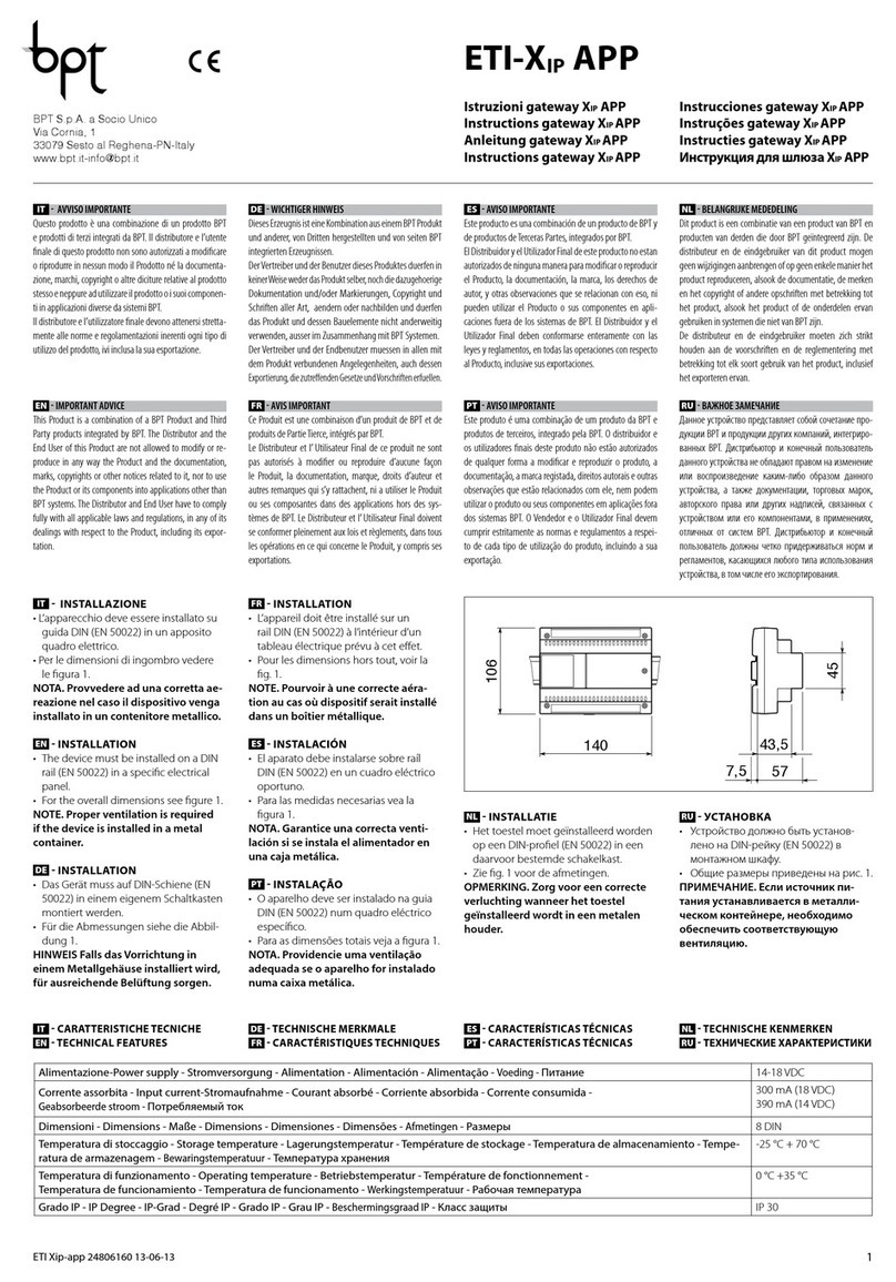
bihl+Wiedemann BWU3683 User manual

Subject to technical modifications; no responsibility is accepted for the accuracy of this information © Bihl+Wiedemann GmbH 1
Internet: www.bihl-wiedemann.de • Flosswoerthstr. 41 • D-68199 Mannheim phone: +49 621 33 996-0 • fax: +49 621 33 922 399
Ausgabedatum: 13.02.2019
ASi-3 CIP Safety über EtherNet/IP + ModbusTCP Gateway
Montageanweisung // Commissioning Instructions // ...
Montageanweisung // Installation Instructions // Notice de montage //
Istruzioni per il montaggio // Instrucciones de montaje
BWU3683
ASi-3 CIP Safety über EtherNet/IP+Modbus TCP Gateway mit integr. Sicherhe-
itsmonitor //
ASi-3 CIP Safety over EtherNet/IP+Modbus TCP-Gateway with integr. Safety
Monitor //
Passerelle ASi-3 CIP Safety via EtherNet/IP+Modbus TCP + moniteur de sécu-
rité intégré //
Gateway ASi-3 CIP Safety sulla EtherNet/IP+Modbus TCP con monitor di
sicurezza integrato //
Pasarela ASi-3 CIP Safety a vía de EtherNet/IP+Modbus TCP + monitor de
seguridad integrado
(Abbildung ähnlich // figure similar // figure similaire // figura simile // figura similar)
Das Gerät beherrscht mehrere Protokolle! Wählen Sie bitte bei der Inbetriebnahme
eines der beiden Protokolle aus. // The device handels multiple protocols! Please se-
lect one of them during the initial operation. // L'appareil maîtrise plusieurs de proto-
coles! Veuillez choisir à la première mise en service l’une des deux protocoles. // Lo
strumento parla due protocolli. Si prega di selezionare alla prima messa in servizio
uno dei due protocolli. // El dispositivo maneja varios protocolos! Por favor selecci-
one uno de los dos protocolos durante la puesta en marcha.
Login:
https://www.bihl-wiedemann.de
download
Anleitung lesen:
Bevor Sie mit dem Gerät arbeiten: Lesen Sie diese Anleitung komplett durch. Alle Sicherheitshinweise und
Vorgaben des Gerätehandbuchs und des Handbuchs zur Konfigurationssoftware sind einzuhalten! //
Read instruction:
Before working with this unit: read these instructions carefully and completely. All notes on safety and speci-
fications of the device manual and the manual for the configuration software are to be considered! //
Lire les instructions:
Avant de travailler avec ce module, veuillez lire l’intégralité de ces instructions. Observez les consignes de
sécurité et les instructions du manuel d’utilisation de l’appareil et du guide utilisateur du logiciel de
configuration. //
Leggere attentamente le istruzioni:
Prima di iniziare a operare sull'apparecchio, leggere attentamente le seguenti istruzioni. Si prega di tenere
conto anche delle indicazioni di sicurezza e delle istruzioni del manuale d’uso dell’apparecchio e del man-
uale per l’utente per il software di configurazione. //
Lea las instrucciones:
Antes de trabajar con el equipo lea por completo el manual de instrucciones. Todas las notas de seguridad
y especificaciones del manual del equipo y del manual del software de configuración deben ser respetadas.

2Subject to technical modifications; no responsibility is accepted for the accuracy of this information © Bihl+Wiedemann GmbH
Internet: www.bihl-wiedemann.de • Flosswoerthstr. 41 • D-68199 Mannheim phone: +49 621 33 996-0 • fax: +49 621 33 922 399
ASi-3 CIP Safety über EtherNet/IP + ModbusTCP Gateway
Montageanweisung // Commissioning Instructions // ...
Ausgabedatum: 13.02.2019
1 Sicherheitshinweise // Safety notes // Indications de sécurité // Indicazioni di
sicurezza // Indicaciones de seguridad
Fachgerecht installieren:
Die elektrische Installation ist von eingewiesenem Fachpersonal durchzuführen. Bei der Installation ist da-
rauf zu achten, dass Versorgungs- und Signalleitungen und auch die ASi Busleitung getrennt von Krafts-
tromleitungen verlegt sind. Im Schaltschrank ist darauf zu achten, dass bei Schützen eine entsprechende
Funkenlöschung verwendet wird. Bei Antriebsmotoren und -bremsen ist auf die Installationshinweise in den
entsprechenden Bedienungsanleitungen zu achten. Bitte beachten Sie, dass die maximale Leitungslänge
für die ASi Busleitung 100 m beträgt. Darüber hinausgehende Leitungslängen erfordern den Einsatz einer
geeigneten Leitungsverlängerung. //
Ensure appropriate installation:
Electrical installation is to be performed by trained expert personnel. During installation care must be taken
that supply and signal leads and also the ASi bus cable are laid separately from power cables. In the switch-
gear cabinet it must be ensured that appropriate spark-quenching equipment is used with contactors.
Where drive motors and brakes are used, attention must be paid to the installation instructions in the cor-
responding operating instructions. Please note that the maximum line length of the ASi bus cable is 100 m.
Cables above that length require the use of a suitable circuit extension. //
Veuillez installer le module de manière adaptée:
L’installation électrique ne doit être effectuée que par du personnel qualifié. Pendant l’installation verifier
que les lignes d’alimentation et de signaux ainsi que la ligne de bus ASi sont posées séparément des câbles
de courant fort. Dans l’armoire électrique, il faut veiller à ce qu’une extinction des etincelles appropriée soit
utilisée avec des contacteurs. Pour les moteurs d’entraînement et les freins, les instructions d’installation
indiquées dans les instructions d’utilisation doivent être réspectées. La longueur maximale autorisée pour
la ligne de bus ASi est de 100 m. Pour atteindre des lignes plus longues il faut utiliser une extension de ligne
appropriée. //
Assicurarsi che l’apparecchio sia installato in modo corretto:
L'installazione e la messa in funzione devono essere eseguite solamente da personale qualificato. Durante
l’installazione, verificare che le linee di alimentazione e di segnali e anche la linea bus ASi vengono posate
separatamente dai cavi a corrente forte. Nell’armadio elettrico, si deve fare attenzione di utilizzare un’es-
tinzione scintille adeguata con i contattori. Per i motori di propulsione e i freni bisogna badare alle istruzioni
per il montaggio indicate nelle istruzioni per l’uso. La lunghezza massima autorizzata per la linea di bus
ASi è di 100 m. Per ottenere delle linee più lunghe si deve utilizzare un´ estenzione di linea adatta. //
Asegúrese de que la instalación se ha realizado de forma correcta:
La instalación eléctrica debe ser efectuada por personal debidamente cualificado. En la instalación se debe
tomar en consideración que los cables de alimentación, los cables de señal y el del bus ASi deben estar
separados de los cables de alta tensión. En el armario eléctrico se debe prestar atención en utilizar equipos
con la función para extinguir arcos en los contactores. Para los motores y frenos del accionamiento se de-
ben acatar las instrucciones de instalación de los mismos. Por favor considere que la máxima extensión
del bus ASi es de 100 m. Instalaciones que excedan esta longitud requieren del uso de extensores conve-
nientes del circuito.

Subject to technical modifications; no responsibility is accepted for the accuracy of this information © Bihl+Wiedemann GmbH 3
Internet: www.bihl-wiedemann.de • Flosswoerthstr. 41 • D-68199 Mannheim phone: +49 621 33 996-0 • fax: +49 621 33 922 399
Ausgabedatum: 13.02.2019
ASi-3 CIP Safety über EtherNet/IP + ModbusTCP Gateway
Montageanweisung // Commissioning Instructions // ...
GEFÄHRLICHE SPANNUNG:
Vor Installations-, Wartungs- oder Änderungsarbeiten: Schalten Sie Ihre Anlage spannungsfrei. Stellen Sie
sicher, dass sie nicht versehentlich wieder eingeschaltet werden kann! //
HAZARDOUS VOLTAGE:
Before any installation, maintenance or modification work: Disconnect your system from the supply network.
Ensure that it cannot be reconnected inadvertently! //
TENSION DANGEREUSE:
Avant le début des travaux d'installation, d'entretien ou de modification: Commutez le module hors tension.
Assurez-vous qu'il ne peut pas être remise par erreur! //
TENSIONE PERICOLOSA:
Prima di eseguire lavori di installazione, manutenzione o modifica: disinserire il sistema, assicurarsi che sia
privo di tensione e che la stessa non possa essere reinserita inavvertitamente! //
TENSIÓN PELIGROSA:
Antes de iniciar trabajos de instalación, mantenimiento o modificación: desconecte su instalación. ¡Cer-
ciórese de que no pueda ser conectada nuevamente por descuido!
Personenschutzfunktion:
Das Gerät erfüllt eine Personenschutzfunktion. Unsachgemäßer Einbau beeinträchtigt die Funktion! Der
Hersteller der Maschine/Anlage, an der das sicherheitsgerichtete System eingesetzt wird, ist verantwortlich
für die korrekte und sichere Gesamtfunktion aller einzelnen Sicherheitskomponenten! Je nach Auswahl der
verwendeten Sicherheitsbauteile kann die Einstufung des gesamten Sicherheitssystems auch in eine nie-
drigere Sicherheitskategorie erfolgen! //
Person protective function:
The device fulfills a person protective function. Inappropriate installation puts the function in risk! The man-
ufacturer of the machine/plant at that one the safety related devices is used is responsible for the correct
and safe total function of all single safety components! Depending on the choice of safety components to
be used the safety system as a whole may also be assigned to a lower safety category. //
Mesures de protection personnelle:
Le dispositif remplit des exigences de protection personnelle. Le montage inapproprié porte atteinte à cette
fonction! Le fabricant de la machine/application dans laquelle le système de sécurité est installé, assume
la résponsabilité pour le fonctionnement correct et sûr de chacun des composants de sécurité! Il en peut
résulter, en fonction des composants de sécurité utilisés, le classement dans une catégorie de sécurité
inférieure! //
Mezzi di protezione personale:
Il dispositivo soddisfa le esigenze di protezione personale. Il montaggio non appropriato danneggia questa
funzione! Il fabbricante della macchina/dell’applicazione nella quale il sistema di sicurezza viene installata,
assume la responsabilità per il funzionamento corretto e sicuro di ognuno dei componenti di sicurezza! Ne
può risultare, in funzione dei componenti di sicurezza utilizzati, la classificazione in una categoria inferiore! /
Medidas de protección de personas:
El dispositivo cumple la función de proteger a las personas. Una instalación inapropiada de los mismos re-
percute en esta función! El fabricante de la máquina o planta, en la cual será utilizado el sistema de segu-
ridad, es responsable del correcto funcionamiento de cada uno de los componentes de seguridad! La
selección de los elementos de seguridad puede derivar en un nivel de seguridad del sistema menor.
Sorgen Sie dafür, dass das Gerät nach seiner Verwendung der Wiederverwertung (Recycling) zugeführt
wird. // You are requested to make sure that the unit will be recycled by the end of its service life. // Veillez
à ce que le module soit recyclé après usage. // Provvedere affinché il dispositivo, dopo l'utilizzo, sia desti-
nato al riciclaggio. // Le solicitamos de que se asegure de que el equipo sea reciclado una vez desechado.

4Subject to technical modifications; no responsibility is accepted for the accuracy of this information © Bihl+Wiedemann GmbH
Internet: www.bihl-wiedemann.de • Flosswoerthstr. 41 • D-68199 Mannheim phone: +49 621 33 996-0 • fax: +49 621 33 922 399
ASi-3 CIP Safety über EtherNet/IP + ModbusTCP Gateway
Montageanweisung // Commissioning Instructions // ...
Ausgabedatum: 13.02.2019
2 Frontansicht und Anschlüsse // Front view and connections // Vue de face
et raccordements //Vista frontale e collegamenti //Vista frontal y conexiones
+-
+-+-
+ASI 1–
+ASI 1–
+
+ASI 2–
ASI +PWR– (max. 8 A)
+ASI
1+ASI
2ASI
+PWR
+ASI
1
+-
[1]
[2]
[4]
[5]
[6]
[3]
[3]
+ASI 1–
Anschluss ASi Kreis 1 // Connection ASi circuit 1 // Raccordement bus ASi 1 // Collegamento circuito ASi 1 // Conexión
circuito ASi 1
+ASI 2 –
Anschluss ASi Kreis 2 // Connection ASi circuit 2 // Raccordement bus ASi 2 // Collegamento circuito ASi 2 // Conexión
circuito ASi 2
ASI +PWR– (max. 8 A)
Versorgungsspannung ASi Kreis // Supply voltage ASi circuit // Tension d’alimentation bus ASi // Tensione di alimentazi-
one circuito ASi // Tensión de alimentación circuito ASi
[1] Chipkarte // Chip card // Carte de puce // Chip card // Tarjeta chip
[2] Diagnose-Schnittstelle // Diagnostic interface // Interface de diagnostic // Interfaccia diagnostica // Interfaz de diag-
nóstico
[3] LED-Statusanzeige // LED status display // Affichage d’état LED // Visualizzazione LED // LED visualización
[4] Feldbus-Schnittstelle // Fieldbus interface // Interface bus de terrain // Interfaccia bus di campo // Interfaz bus de
campo
[5] LC-Anzeige // LC display // Affichage LC // Visualizzazione LC // Display LC
[6] Tasten für Handbedienung // Buttons for hand operation // Boutons pour commande manuelle // Pulsanti per le
impostazioni manuali // Teclas para accionamiento manual

Subject to technical modifications; no responsibility is accepted for the accuracy of this information © Bihl+Wiedemann GmbH 5
Internet: www.bihl-wiedemann.de • Flosswoerthstr. 41 • D-68199 Mannheim phone: +49 621 33 996-0 • fax: +49 621 33 922 399
Ausgabedatum: 13.02.2019
ASi-3 CIP Safety über EtherNet/IP + ModbusTCP Gateway
Montageanweisung // Commissioning Instructions // ...
LED Beschreibung // Description // Description // Descrizione // Descripción
net (1) Ethernet Kommunikation aktiv // Ethernet Master recognized // Ethernet maître reconnu // master
Ethernet riconosciuto // Maestro Ethernet detectado
Tab. 1-1.
config error
U ASi
ASi active
prg enable
prj mode
power
net
Power (1) Spannung EIN // power ON // tension présente // tensione ON // tensión ON
config error (2) Konfigurationsfehler // configuration error // erreur de configuration // errore di configurazione //
error de configuración
U ASi (1) ASi Spannung o.k. // ASi voltage o.k. // tension ASi présente // tensione ASi o.k. // tensión ASi
O.K.
ASi active (1) ASi Betrieb normal // ASi normal operation active // ASi en fonctionnement normal // funziona-
mento ASi normale // funcionamiento ASi normal
prg enable (1)
automatische Slaveprogrammierung möglich // automatic address programming enabled // confi-
guration automatique des adresses activée // programmazione automatica degli slave possibile //
programación automática de esclavo factible
prj mode (3) Projektierungsmodus aktiv // master is in configuration mode // mode configuration actif // modo
progettazione attivo // modo de configuración activo
Tab. 1-2.
(1) LED grün/green/vert/verde/verde (2) LED rot/red/rouge/rosso/rojo (3) LED gelb/yellow/jaune/giallo/amarillo
LED an/on/allumée/on/en LED blinkend/flashing/clignotante/ampeggiante/el destellar aus/off/éteinte/fuori/fuera
T2 SI2 SI4 SI6
T1 SI1 SI3 SI5
SO3
0V SO6
SO4
SO5
SO1
24V
SO2

6Subject to technical modifications; no responsibility is accepted for the accuracy of this information © Bihl+Wiedemann GmbH
Internet: www.bihl-wiedemann.de • Flosswoerthstr. 41 • D-68199 Mannheim phone: +49 621 33 996-0 • fax: +49 621 33 922 399
ASi-3 CIP Safety über EtherNet/IP + ModbusTCP Gateway
Montageanweisung // Commissioning Instructions // ...
Ausgabedatum: 13.02.2019
SI1, SI2, SI3, SI4, SI5, SI6
Die Eingänge können für potentialfreie Kontakte oder OSSDs, oder als Standardeingänge kon-
figuriert werden. // Inputs either for connecting of floating contacts, or OSSDs, or standard
inputs. // Les entrées peuvent être configurées pour des contacts sans potentiel ou pour des
OSSD, ou comme des entrées standard. // Gli ingressi possono essere configurati per i contatti a
potenziale zero, OSSD o per gli ingressi standard. // Las entradas se pueden configurar para
contactos libres de potencial, OSSDs o entradas estándar
SO1, SO2, SO3, SO4, SO5, SO6
Die Halbleiterausgänge sind kurzschluss- und überlastfest. Die Klemmen SO1 … SO6 können
auch als sicherheitsgerichtete Eingänge für potentialfreie Kontakte oder als Standardeingänge
konfiguriert werden. Max. Kontaktbelastbarkeit: 1,2 ADC-13 bei 30 V, = 7,2 A gesamt (Derating
beachten). // Semiconductor outputs are short-circuit-and overload protected. Clamps
SO1 … SO6 either for connecting of floating contacts or OSSDs or standard inputs. Max. contact
load: 1,2 ADC-13 at 30 V, = 7,2 A total (consider Derating!). // Les sorties à semi-conducteur
sont protégées contre les court-cirtcuits et les surcharges. Les bornes SO1 … SO6 peuvent éga-
lement être configurées comme des entrées de sécurité pour des contacts sans potentiel ou
comme des entrées standard. Charge max. des contacts : 1,2 ACC-13 sous 30 V, = 7,2 A au
total (tenir compte du derating). // Uscite a semiconduttore sono protette contro il corto circuito ed
i sovraccarichi. I morsetti SO1 … SO6 possono anche essere configurati come ingressi di sicu-
rezza per contatti senza potenziale o come ingressi standard. Max. carico sui contatti: 1,2 ACC-13
a 30 V, = 7,2 A in totale (tenere conto del derating). // Salidas de semiconductor resistente a
cortocircuitos y sobrecarga. Los bornes SO1 … SO6 también se pueden configurar como entra-
das de seguridad para contactos libres de potencial o como entradas estándar. Máx. capacidad
de carga: 1,2 ACC-13 a 30 V, = 7,2 A total (observar el derating).
T1, T2
Taktausgänge zum Anschluss von potentialfreien Kontakten. Strombegrenzung auf 125 mA. //
Clock outputs for connecting of floating contacts. Current limitation up to 125 mA. // Sorties d’hor-
loge pour le raccordement à des points de contact sans potentiel. Limitation de courant à
125 mA. // Uscite di clock di prova per il collegamento di contatti a potenziale zero. Limitazione
della corrente a 125 mA. // Salidas de ciclo para la conexión de contactos libres de potencial.
Limitación de corriente a 125 mA.
0V,24V
Versorgung der Halbleiter- und Testausgänge, sowie der Eingänge aus separaten 24 VDC. Die
Spannung muss auch im Falle eines Fehlers kleiner als 42 V sein. // Supply for semiconductor
and test outputs as well for inputs out of auxiliary 24 VDC. Even in case of a fault, the voltage
shall be 42 V or less. // Alimentation des sorties à semi-conducteur, des sorties d’essai et des
entrées à partir de 24 VCC à part. Même en cas d'erreur, la tension doit être inférieure à
42 V. // Alimentazione delle uscite di prova come pure le ingressi da 24 VCC separati. La tensi-
one deve essere anche in caso di un errore più piccola di 42 V. // Alimentación de las salidas de
semiconductor y las salidas de prueba así como las entradas desde 24 VCC separadas. La máx-
ima tensión debe ser, aún en caso de un error, 42 V o menos.

Subject to technical modifications; no responsibility is accepted for the accuracy of this information © Bihl+Wiedemann GmbH 7
Internet: www.bihl-wiedemann.de • Flosswoerthstr. 41 • D-68199 Mannheim phone: +49 621 33 996-0 • fax: +49 621 33 922 399
Ausgabedatum: 13.02.2019
ASi-3 CIP Safety über EtherNet/IP + ModbusTCP Gateway
Montageanweisung // Commissioning Instructions // ...
LEDs Beschreibung // Description // Description // Descrizione // Descripción
SI1 + SI2
SI3 + SI4
SI5 + SI6
2 Eingänge = 1 sicherer Eingang // 2 inputs = 1 safe input // 2 entrées = 1 entrée de sécurité //
2 ingressi = 1 ingresso di sicurezza // 2 entradas = 1 entrada segura
Blinken im Gleichtakt -> Querschluss // flashing in common mode -> cross-circuit // cligno-
tement en mode commun -> court-circuit // intermitencias en fase -> cortocircuito // par-
padeo en fase -> cortocircuito transversal
(3) 1 Hz
Blinken im Gegentakt -> Eingang testen // flashing in push-pull mode -> test input // cligno-
tement en mode différentiel -> tester l’entrée // intermitencias en contrafase -> testare
l'ingresso // parpadeo en contrafase -> comprobar entrada
1Hz
aus -> Kanal offen // off -> channel open // éteint -> canal ouvert // off -> canale aperto //
apagado -> canal abierto
an -> Kanal geschlossen // on -> channel closed // allumé -> canal fermé // on -> canale
chiuso // encendido -> canal cerrado
SO1 + SO2
SO3 + SO4
SO5 + SO6
verwendet als sicherer Eingang // used as safe input // s’utilise comme entrée de sécurité // usato
come ingresso sicuro // utilizado como entrada segura
Blinken im Gleichtakt -> Querschluss // flashing in common mode -> cross-circuit // cligno-
tement en mode commun -> court-circuit // intermitencias en fase -> cortocircuito // par-
padeo en fase -> cortocircuito transversal
(3)1 Hz
Blinken im Gegentakt -> Eingang testen // flashing in push-pull mode -> test input // cligno-
tement en mode différentiel -> tester l’entrée // intermitencias en contrafase -> testare
l'ingresso // parpadeo en contrafase -> comprobar entrada
1Hz
aus -> Kanal offen // off -> channel open // éteint -> canal ouvert // off -> canale aperto //
apagado -> canal abierto
an -> Kanal geschlossen // on -> channel closed // allumé -> canal fermé // on -> canale
chiuso // encendido -> canal cerrado
SO1 … SO6
verwendet als Ausgang // used as output // S’utilise comme sortie // usato come uscita // utilizado
como salida
(3)
1Hz
Blinken -> Überlast // flashing -> overload // clignotement en mode commun ->
surcharge // intermitencias en fase -> sovraccarico // parpadeo -> sobrecarga
aus -> Ausgang ist nicht geschaltet // off -> output is not switched // éteint -> sortie n'est
pas activée // off -> l'uscita non ha commutato // apagado -> la salida no ha conmutado
an -> Ausgang ist geschaltet // on -> output is switched // allumé -> sortie est activée //
on -> l'uscita ha commutato // encendido -> la salida ha conmutado
SI1 … SI6
SO1 … SO6 (3)
1Hz
Blinken im Gleichtakt (alle) -> Schwerwiegender Fehler // flashing in common mode (all) ->
fatal error // clignotement en mode commun (tous) -> erreur grave // intermitencias en fase
(tutti) -> errore grave // parpadeo en fase (todos) -> fallo grave
AUX (1) ASi PWR und 24VDC AUX an // ASi PWR and 24VDC AUX on // ASi PWR et 24VDC AUX
on // ASi PWR e 24VDC AUX on // ASi PWR y 24VDC AUX activada
(1) LED grün/green/vert/verde/verde (2) LED rot/red/rouge/rosso/rojo (3) LED gelb/yellow/jaune/giallo/amarillo
LED an/on/allumée/on/en LED blinkend/flashing/clignotante/ampeggiante/el destellar aus/off/éteinte/fuori/fuera

8Subject to technical modifications; no responsibility is accepted for the accuracy of this information © Bihl+Wiedemann GmbH
Internet: www.bihl-wiedemann.de • Flosswoerthstr. 41 • D-68199 Mannheim phone: +49 621 33 996-0 • fax: +49 621 33 922 399
ASi-3 CIP Safety über EtherNet/IP + ModbusTCP Gateway
Montageanweisung // Commissioning Instructions // ...
Ausgabedatum: 13.02.2019
3 Abmessungen //Dimensions //Dimensions //Dimensioni //Dimensiones [mm]
4 Montage // Installation // Montage // Montaggio // Montaje
5 Elektrische Installation // Electrical Installation // Installation électrique //
Installazione elettrica // Instalación eléctrica
110
80 120
90 10
106
125
86
80
1
2
3
+-
+-+-
Auf Montageplatte mit 35 mm-Hutschiene // On mounting plate with 35 mm top-hat
rail // Sur plaque de montage avec profilé-support 35 mm // Su piastra di montaggio
con guida DIN 35 mm // Sobre placa de montaje con guía simétrica de 35 mm
Einbaulage vertikal! // Vertical mounting position! // Position de montage verticale! //
Montaggio verticale! // Posición de montaje vertical!
+ASI 1- +ASI 1- +ASI 2- ASI
+PWR- ASI
PWR
GND
ASI +PWR– (max. 8 A)
+ASI 2–
+ASI 1–
+ASI 1–
Spannungs-
versorgung //
Power supply //
Alimentation //
Alimentazione //
Alimentación
10
10
AWG 24 ... 12
0,2 ... 2,5 mm
2
0,2 ... 2,5 mm
2
Anlagenmasse // System ground // Terre de système //
Terra del sistema // Tierra del sistema

Subject to technical modifications; no responsibility is accepted for the accuracy of this information © Bihl+Wiedemann GmbH 9
Internet: www.bihl-wiedemann.de • Flosswoerthstr. 41 • D-68199 Mannheim phone: +49 621 33 996-0 • fax: +49 621 33 922 399
Ausgabedatum: 13.02.2019
ASi-3 CIP Safety über EtherNet/IP + ModbusTCP Gateway
Montageanweisung // Commissioning Instructions // ...
Bei starker EMV Belastung, wird eine zusätzliche Erdung über die Erdungsklemme
des Gateways zur Anlagenmasse empfohlen, für eine störsichere Kommunikation im
ASi System. // In environments subject to high levels of EMC, an additional earth on
the earth terminal of the gateway to the system ground is recommended to ensure
interference-free communication in the ASi system. // Dans les environnements à
fortes charges électromagnétiques, une mise à la terre supplémentaire via la borne de
terre de la passerelle vers la terre de système est recommandée, pour assurer une
communication exempte d'interférences dans le système ASi. // Negli ambienti sog-
getti a elevati livelli di EMC, per una comunicazione senza disturbi nel sistema ASi si
consiglia di utilizzare una connessione di terra addizionale eseguita dal terminale di
terra del gateway alla terra del sistema. // En ambientes con fuerte carga de compatib-
ilidad electromagnética se recomienda una conexión a Tierra adicional a través del
conector de Tierra del sistema de la pasarela, a fin de que la comunicación en el
sistema ASi sea segura contra fallos y averías.
+ASI 1- +ASI 1- +ASI 2- ASI
+PWR- ASI
PWR
GND
ASI +PWR– (max. 8 A)
+ASI 2–
+ASI 1–
+ASI 1–
Spannungs-
versorgung //
Power supply //
Alimentation //
Alimentazione //
Alimentación
10
10
AWG 24 ... 12
0,2 ... 2,5 mm
2
0,2 ... 2,5 mm
2
Anlagenmasse // System ground // Terre de système //
Terra del sistema // Tierra del sistema
Umgebungstemperatur // Ambient air temperature //
Température d'environnement // Temperatura ambiente //
Temperatura del aire ambiente
max. +55 °C (UL)
Temperaturbereich für Kabel // Temperature rating for cable /
/ Evaluation de température pour câble // Temperatura nomi-
nale per cavi // Temperatura nominal para cables
60/75 oC
Nur Kupferleitungen verwenden // Use copper conductors
only // Utilisez uniquement des conducteurs cuivre // Utiliz-
zare conduttori in rame // Utilice sólo conductores de cobre

10 Subject to technical modifications; no responsibility is accepted for the accuracy of this information © Bihl+Wiedemann GmbH
Internet: www.bihl-wiedemann.de • Flosswoerthstr. 41 • D-68199 Mannheim phone: +49 621 33 996-0 • fax: +49 621 33 922 399
ASi-3 CIP Safety über EtherNet/IP + ModbusTCP Gateway
Montageanweisung // Commissioning Instructions // ...
Ausgabedatum: 13.02.2019
5.1 Umstellung auf ASi Power24V-Versorgung // Switching to the ASi Power24V
supply // Passage à l'alimentation ASi Power24V // Conversione su
alimentazione ASi Power24V // Cambio a alimentación ASi Power24V
Vorsicht! // Caution! // Attention! // Attenzione! // Atención!
Am schwarzen Kabel für das Netzteil dürfen keine Slaves oder Repeater angeschlos-
sen werden. Am gelben Kabel für den ASi Anschluss dürfen keine ASi Netzteile oder
weitere Master angeschlossen werden. Die maximale Ausgangsspannung des Netz-
teils muss auch im Falle eines Fehlers kleiner als 42 V sein. // At the black cable for
power supply no slaves or repeaters may be attached. At the yellow cable for ASi cir-
cuit no power supplies or further masters may be attached. Even in case of a fault, the
output voltage of the power supply shall be 42 V or less. // Au câble noir pour l'alimen-
tation aucun esclave ou répéteur ne peut être raccordé. Au câble jaune pour le circuit
ASi aucune alimentation ou autre maître ne peut être raccordé. Même en cas d'erreur,
la tension de sortie maximale de l'alimentation doit être inférieure à 42 V. // Al cavo
nero per l’alimentazione nessuno slave o ripetitore può essere collegato. Al cavo giallo
per il circuito ASi nessun alimentatore o altro master può essere collegato. La massi-
male tensione di uscita dell alimentatore deve essere anche in caso di un errore più
piccola di 42 V. // En el cable negro de la alimentación ASi no se deben conectar
esclavos o repetidores. En el cable amarillo del circuito ASi no se debe conectar nin-
guna fuente de alimentación ASi u otro master. La máxima tensión de salida de la
fuente de alimentación debe ser, aún en caso de error, 42 V o menos.
|QUICK SETUP |
...
|SETUP |
|OPERATION MODE |
...
|POWER SUPPLY |
|POWER SUPPLY |
|ASi PWR SUPPLY |
|CHANGE |
|POWER SUPPLY |
|24V GROUNDED |
|CHANGE |

Subject to technical modifications; no responsibility is accepted for the accuracy of this information © Bihl+Wiedemann GmbH 11
Internet: www.bihl-wiedemann.de • Flosswoerthstr. 41 • D-68199 Mannheim phone: +49 621 33 996-0 • fax: +49 621 33 922 399
Ausgabedatum: 13.02.2019
ASi-3 CIP Safety über EtherNet/IP + ModbusTCP Gateway
Montageanweisung // Commissioning Instructions // ...
6 Idealaufbau eines ASi Kreises // Model structure of an ASi network //
Structure idéal d’un circuit ASi // Struttura ideale di circuito ASi //
Estructura modelo del circuito ASi
Über das Display-Menü vorgenommene Einstellungen können durch die Steuerung
überschrieben werden! // Settings made via the display menu can be overwritten by the
control! // Les réglages effectués via le menu de l'afficheur peuvent être écrasés par la
commande! // Le impostazioni eseguite dal menu del display possono essere sovras-
critte dal controllo! // ¡Los ajustes realizados a través del menú de display pueden ser
sobrescritos por el control!
Legende // Legend // Légende // Leggenda // Leyenda
Gateway m. integriertem Sicherheitsmonitor //
Gateway w. integrated Safety Monitor //
Passerelle a. Monitor de sécurité intégré //
Gateway c. Monitor di sicurezza integrato //
Pasarella c. Monitor de Seguridad integrado
Netzteil //
Power supply //
Alimentation //
Alimentazione //
Alimentación
Standard Slave //
Standard slave //
Esclave standard //
Slave standard //
Esclavo standard
Safety Slave //
Safety slave //
Esclave de sécurité //
Slave di sicurezza //
Esclavo seguro
100 m
100 m
ASI
PWR
ASI
PWR

12 Subject to technical modifications; no responsibility is accepted for the accuracy of this information © Bihl+Wiedemann GmbH
Internet: www.bihl-wiedemann.de • Flosswoerthstr. 41 • D-68199 Mannheim phone: +49 621 33 996-0 • fax: +49 621 33 922 399
ASi-3 CIP Safety über EtherNet/IP + ModbusTCP Gateway
Montageanweisung // Commissioning Instructions // ...
Ausgabedatum: 13.02.2019
7 Anschlussbeispiele // Connection examples // Exemples de raccordement //
Esempi di collegamento // Ejemplos de conexión
7.1 Anschluss von potentialfreien Kontakten // Connection of floating
contacts // Raccordement des points de contact sans potentiel //
Collegamento di contatti a potenziale zero // Conexión de contactos libres
de potencial
7.2 Anschluss von antivalenten Kontakten // Connection of antivalent contacts
// Raccordement des contacts antivalents // Collegamento di contatti
antivalenti // Conexión de contactos antivalentes
T2 SI2 SI4 SI6
T1 SI1 SI3 SI5
T2 SI2 SI4 SI6
T1 SI1 SI3 SI5

Subject to technical modifications; no responsibility is accepted for the accuracy of this information © Bihl+Wiedemann GmbH 13
Internet: www.bihl-wiedemann.de • Flosswoerthstr. 41 • D-68199 Mannheim phone: +49 621 33 996-0 • fax: +49 621 33 922 399
Ausgabedatum: 13.02.2019
ASi-3 CIP Safety über EtherNet/IP + ModbusTCP Gateway
Montageanweisung // Commissioning Instructions // ...
7.3 Anschluss eines Schützes // Connection of contactor // Raccordement d’un
contacteur // Collegamento contattori // Conexión de contactor
7.4 Anschluss von OSSDs // Connection of OSSDs // Raccordement à des
OSSD // Collegamento di OSSD // Conexión de OSSDs
T2 SI2 SI4 SI6
T1 SI1 SI3 SI5
SO3
0V SO6
SO4
SO5
SO1
24V
SO2
SO1
0V
K2
K1
M
1.Y1
I+
+24 V
0 V
SI1
L1 L2 L3
T2 SI2 SI4 SI6
T1 SI1 SI3 SI5
SO3
0V SO6
SO4
SO5
SO1
24V
SO2
24V0V
OSSD4
Transmitter
FE
+24 V
0V
Transmitter
FE
Receiver
FE
OSSD3
24V0V
24V0V
24V
0V
OSSD1
OSSD2
Receiver
FE

14 Subject to technical modifications; no responsibility is accepted for the accuracy of this information © Bihl+Wiedemann GmbH
Internet: www.bihl-wiedemann.de • Flosswoerthstr. 41 • D-68199 Mannheim phone: +49 621 33 996-0 • fax: +49 621 33 922 399
ASi-3 CIP Safety über EtherNet/IP + ModbusTCP Gateway
Montageanweisung // Commissioning Instructions // ...
Ausgabedatum: 13.02.2019
7.5 Drehzahlwächter (1-kanalig) an lokalen Anschlüssen // Speed monitoring
(1-channel) on local connections // Contrôleur de vitesse (1-canal) des
connexions locales // Controllo della velocità (1-canale) agli allacciamenti
locali // Supervisor de revoluciones (1-canal) en conexiones locales
7.6 Drehzahlwächter (2-kanalig) an lokalen Anschlüssen // Speed monitoring
(2-channel) on local connections // Contrôleur de vitesse (2-canal) des
connexions locales // Controllo della velocità (2-canale) agli allacciamenti
locali // Supervisor de revoluciones (2-canal) en conexiones locales
SO3
0V SO6
SO4
SO5
SO1
24V
SO2
SO1
S1
Vorsicht! // Caution! // Attention! // Attenzione! // Atención!
Beim 1-kanaligen Betrieb wird die SIL 1 erfüllt! // When operating in 1-channel mode
the SIL 1 is achieved! // En opérant à un canal, SIL 1 est réalisé!. // In operazione 1-
canale SIL 1 è raggiunto! // En el funcionamiento con 1 canal se cumple SIL 1!
SO3
0V SO6
SO4
SO5
SO1
24V
SO2
SO2
S1
S2
SO1
Vorsicht! // Caution! // Attention! // Attenzione! // Atención!
Beim 2-kanaligen Betrieb wird die SIL 2 erfüllt! // When operating in 2-channel mode
the SIL 2 is achieved! // En opérant à 2 canal, SIL 2 est réalisé! // In operazione 2-
canale SIL 2 è raggiunto! // En el funcionamiento con 2 canales se cumple SIL 2!

Subject to technical modifications; no responsibility is accepted for the accuracy of this information © Bihl+Wiedemann GmbH 15
Internet: www.bihl-wiedemann.de • Flosswoerthstr. 41 • D-68199 Mannheim phone: +49 621 33 996-0 • fax: +49 621 33 922 399
Ausgabedatum: 13.02.2019
ASi-3 CIP Safety über EtherNet/IP + ModbusTCP Gateway
Montageanweisung // Commissioning Instructions // ...
7.7 Konfiguration von Ausgang SO1 als Standard-Eingang // Configuration of
output SO1 as standard input // Configuration de la sortie SO1 comme
entrée de standard // Configurazione dell'uscita SO1 come ingresso
standard // Configuración de la salida SO1 como entrada estándar
7.8 Konfiguration der Ausgänge SO1, SO2 als sicherer Eingang //
Configuration of outputs SO1, SO2 as safe input // Configuration des
sorties SO1, SO2 comme entrée de sécurité // Configurazione delle uscite
SO1, SO2 come ingresso di sicurezza // Configuración de las salidas SO1,
SO2 como entrada de seguridad //
SO3
0V SO6
SO4
SO5
SO1
24V
SO2
ASIMON360
T2 SI2 SI4 SI6
T1 SI1 SI3 SI5
SO3
0V SO6
SO4
SO5
SO1
24V
SO2
ASIMON360

16 Subject to technical modifications; no responsibility is accepted for the accuracy of this information © Bihl+Wiedemann GmbH
Internet: www.bihl-wiedemann.de • Flosswoerthstr. 41 • D-68199 Mannheim phone: +49 621 33 996-0 • fax: +49 621 33 922 399
ASi-3 CIP Safety über EtherNet/IP + ModbusTCP Gateway
Montageanweisung // Commissioning Instructions // ...
Ausgabedatum: 13.02.2019
8 Sichere Konfiguration mit ASIMON360 // Safe configuration using
ASIMON360 // Configuration de sécurité avec ASIMON360 // Configurazione
di sicurezza con ASIMON360 // Configuración de seguridad con
ASIMON360
Vorsicht! // Caution! // Attention! // Attenzione! // Atención!
Werden Ausgänge als Eingänge konfiguriert, muss der Eingangsstrom extern auf
100 mA (träge Sicherung) begrenzt werden. Eingänge dürfen nur aus der gleichen
24 V Quelle wie das Gerät selbst, gespeist werden. // If outputs are set up as inputs,
the input current has to be limited externally to 100 mA (slow-blow fuse). Inputs can
only be supplied by the same 24 V source than the device itself. // Si des sorties sont
configurées comme des entrées, le courant d'entrée doit être limité en externe à
100 mA (fusible lent). Les entrées doivent être alimentées par la même source 24 V
que l'ap-pareil-même. // Se le uscite vengono configurate come ingressi, la corrente in
ingresso deve essere limitata esternamente a 100 mA (fusibile ritardato). Gli ingressi
possono essere alimentati solo dalla stessa sorgente a 24 V dell'apparecchio stesso. /
/ Si se configuran salidas como entradas, se deberá limitar la corriente de entrada
externa a 100 mA (fusible de acción retardada). Las entradas deben ser alimentadas
únicamente desde la misma fuente de 24 V como el propio dispositivo
Start
ASIMON360
Software
Vorsicht! // Caution! // Attention! // Attenzione! // Atención!
Vor der Inbetriebnahme der Sicherheitseinheit das Gateway in Betrieb nehmen! //
Before commissioning the safety unit, put the gateway into operation! // Avant la mise
en service du bloc de sécurité, mettre en service la passerelle! // Prima della messa in
servizio dell’unità di sicurezza, mettere in funzione il gateway! // Ponga en marcha la
pasarela antes de poner en marcha la unidad de seguridad!
ASIMON360 Software
Ändern Sie mit Monitor/Passwortänderung das voreingestellte Passwort "SIMON" bei der ersten
Benutzung des Gerätes! // Change the preset password "SIMON" during the first use of the
device (Monitor/change password)! // Modifier le mot de passe "SIMON" préréglé en usine en
choississant Moniteur/Changement mot de passe lors de la première utilisation de l'appareil! //
Modificare la password "SIMON" impostata in fabbrica scelgiendo Monitor/cambiamento pass-
word quando usate per la prima volta l'apparecchio! // Cambie la contraseña "SIMON" prepro-
gramada de fábrica en la primera utilización del equipo por medio de Monitor/Cambio de
contraseña!

Subject to technical modifications; no responsibility is accepted for the accuracy of this information © Bihl+Wiedemann GmbH 17
Internet: www.bihl-wiedemann.de • Flosswoerthstr. 41 • D-68199 Mannheim phone: +49 621 33 996-0 • fax: +49 621 33 922 399
Ausgabedatum: 13.02.2019
ASi-3 CIP Safety über EtherNet/IP + ModbusTCP Gateway
Montageanweisung // Commissioning Instructions // ...
ASIMON360 Software
Stellen Sie die gewünschte Konfiguration zusammen. // Create the desired configuration. //
Définir la configuration souhaitée. // Stabilire la configurazione desiderata. // Escoja la configura-
ción deseada.
ASIMON360 Software
Spielen Sie die Konfiguration mit MONITOR / PC -> MONITOR ins Gerät. Geben Sie dazu das
Passwort ein. // Download the configuration with MONITOR / PC -> MONITOR into the device.
Enter the password for this purpose. // Enregistrer la configuration en choississant MONITEUR /
MONITEUR -> PC dans l'appareil. Entrer le mot de passe. // Registrare la configurazione
nell'apparecchio scelgiendo MONITOR / MONITOR -> PV. Entrare la password. // Descargue la
configuración con MONITOR / PC -> MONITOR en el monitor. Escriba la clave del aparato para
este efecto..
ASIMON360 Software
Die Abfrage CODEFOLGEN EINLERNEN? können Sie mit "Ja" bestätigen oder den Vorgang
später über das Display ausführen, wenn Sie "Nein" wählen. // You can acknowledge the
request TEACH CODE SEQUENCES? selecting "Yes", or you can do it later via display select-
ing "No". // Sélectionner "Oui" pour répondre affirmativement à la requête APPRENTISSAGE
TABLES DE CODE, ou "No" pour exécuter l'action plus tard via l'afficheur. // Selezionare "Si"
per rispondere affirmativamente alla richiesta TEACH SEQUENZE DI CODICE, o "No" per ese-
guire l'azione più tardi mediante il display. // La pregunta ¿Desea efectuar el aprendizaje de las
secuencias de código? Se puede confirmar con "Sí", o con "No" y luego realizar este proceso
por medio de la pantalla.
ASIMON360 Software
Prüfen Sie das Konfigurationsprotokoll (beachten Sie hierzu die Anweisungen im <Kap. 5.8> der
ASIMON360 Dokumentation!). // Check the configuration log (respect instructions in <chap. 5.8>
of the ASIMON360 manual!). // Contrôler le protocole de configuration (veillez à respecter les
instructions données dans le <chap. 5.8> du manuel du logiciel ASIMON360). // Controllare il
protocollo di configurazione (osservare le istruzioni indicate nel <cap. 5.8> del manuale per il
software ASIMON360). // Compruebe el protocolo de configuración (considere para este caso
las instrucciones en <cap. 5.8> de la documentación de ASIMON360).

18 Subject to technical modifications; no responsibility is accepted for the accuracy of this information © Bihl+Wiedemann GmbH
Internet: www.bihl-wiedemann.de • Flosswoerthstr. 41 • D-68199 Mannheim phone: +49 621 33 996-0 • fax: +49 621 33 922 399
ASi-3 CIP Safety über EtherNet/IP + ModbusTCP Gateway
Montageanweisung // Commissioning Instructions // ...
Ausgabedatum: 13.02.2019
ASIMON360 Software
Geben Sie mit MONITOR –> FREIGABE die Konfiguration frei. // Validate the configuration with
MONITOR –> VALIDATION. // Valider la configuration avec MONITEUR –> LIBÉRATION //
Abilitare la configurazione scelgiendo MONITOR –> ABILITAZIONE. // Habilite la configuración
con MONITOR –> HABILITACION.
ASIMON360 Software
Starten Sie den Monitor mit MONITOR –> START. // Start the monitor with MONITOR –>
START. // Démarrer le moniteur avec MONITEUR –> START. // Avviare il monitor scelgiendo
MONITOR –> START. // Inicie el monitor con MONITOR –> INICIO.
☺PRESS OK FOR MENU
OUTPUT CIRCUIT
1:ON 2:ON
3:ON 4:ON
Das Gerät ist jetzt im geschützten Betriebsmodus. //
The device is in the protected mode now. // L’appareil
est en mode protegé. // L’apparecchio è in modo
protetto. // El equipo se encuentra en modo protegi-
do.
Wird dem Sicherheitsmonitor in der ASIMON360 Software eine eigene Adresse zuge-
wiesen, muss die Projektierung im ASi Master (Quick Setup) angepasst werden! Dies
gilt auch bei der Verwendung von simulierten Slaves. // If you have assigned the safety
monitor its own address in the software ASIMON360, adjust the configuration in the
ASi master (Quick Setup)! This is also valid when using simulated slaves. // Si le moni-
teur de sécurité se voit attribuer une adresse propre dans le logiciel ASIMON360, la
planification doit être adaptée au niveau du maître ASi (Quick Setup)! Ceci est égale-
ment valable lors de l’utilisation d'esclaves simulés. // Se si assegna al monitor di
sicurezza un indirizzo proprio nel software ASIMON360, si deve adeguare la proget-
tazione nel master ASi (Quick Setup)! Ciò vale anche quando si usano slave simulati. /
/ ¡Si se le asigna una dirección propia al monitor de seguridad en el software ASI-
MON360, será preciso adaptar la concepción en el máster ASi (Quick Setup)! Esto
también será válido si se utilizan esclavos simulados.
Beachten Sie bitte weitere Sicherheitshinweise im Handbuch ASIMON360! // Please
consider notes on safety in the software manual ASIMON360! // Veuillez observer
d'autres indications de sécurité exposées dans le manuel ASIMON360! // Si prega di
osservare altre indicazioni di sicurezza riportate nel manuale ASIMON360! // Preste
particular atención a las notas de seguridad escritas en el manual ASIMON360!

Subject to technical modifications; no responsibility is accepted for the accuracy of this information © Bihl+Wiedemann GmbH 19
Internet: www.bihl-wiedemann.de • Flosswoerthstr. 41 • D-68199 Mannheim phone: +49 621 33 996-0 • fax: +49 621 33 922 399
Ausgabedatum: 13.02.2019
ASi-3 CIP Safety über EtherNet/IP + ModbusTCP Gateway
Montageanweisung // Commissioning Instructions // ...
8.1 Safe Link
...
Dokumentation // Documentation // Documentation // Documentazione //
Documentación
"ASIMON360"
Wird die Ethernet-Diagnoseschnittstelle für die sichere Kopplung Safe Link bzw. für die
Kommunikation mit der ASIMON360 Software verwendet, müssen die Geräte über
einen externen Switch verbunden werden! // The devices have to be connected to an
external switch, if using the ethernet diagnostic interface for safe coupling (via) Safe
Link respectively for the connection with the ASIMON360 software! // Si l'interface de
diagnostic d'Ethernet est utilisée pour la communication de sécurité Safe Link repecti-
vement pour la communication avec le logiciel ASIMON360, les dispositifs doivent être
reliées par un commutateur externe! // Se si usa l'interfaccia di diagnosi Ethernet per
l'accoppiamento sicuro Safe Link o per la comunicazione con il software ASIMON360,
si devono collegare gli apparecchi tramite un interruttore esterno! // ¡Si se utiliza la
interfaz de diagnóstico Ethernet para el acoplamiento de seguridad Safe Link o para la
comunicación con el software ASIMON360, se deberán unir los dispositivos a través
de un conmutador externo

20 Subject to technical modifications; no responsibility is accepted for the accuracy of this information © Bihl+Wiedemann GmbH
Internet: www.bihl-wiedemann.de • Flosswoerthstr. 41 • D-68199 Mannheim phone: +49 621 33 996-0 • fax: +49 621 33 922 399
ASi-3 CIP Safety über EtherNet/IP + ModbusTCP Gateway
Montageanweisung // Commissioning Instructions // ...
Ausgabedatum: 13.02.2019
9 Inbetriebnahme am Gerät // Commissioning via the device // Mise en service
via le disositif // Messa in servizio tramite il dispositivo // Puesta en servicio
mediante la unidad
9.1 Wechsel in erweiterten Modus // Switching to advanced display mode //
Passage dans le mode étendu // Passaggio nel modo esteso // Cambio al
modo avanzado
9.2 Modbus TCP auswählen // Select Modbus TCP // Sélectionner Modbus TCP /
Selezionare Modbus TCP // Seleccionar Modbus TCP
Menüaufbau siehe Zusatzblatt //
Menu structure see additional page //
Structure de menu voir page supplémentaire //
Struttura di menu vedi pagina supplementare //
Estructura del menu ver página adicional
Klassische Anzeige //
Classical display //
Affichage classique //
Display classico //
Indicación clásica
LCD
1.12A
UNKNOWN SLAVE
LCD
ETHERNET
QUICK SETUP
SAFETY
DIAGNOSIS
Erweiterter Anzeigemodus //
Advanced display mode //
Mode d‘affichage étendu //
Modo di visualizzazione avanzata //
Modo de visualisación avanzada
Das Gerät beherrscht mehrere Protokolle! Wählen Sie bitte bei der Inbetriebnahme
eines der beiden Protokolle aus. // The device handels multiple protocols! Please se-
lect one of them during the initial operation. // L'appareil maîtrise plusieurs de proto-
coles! Veuillez choisir à la première mise en service l’une des deux protocoles. // Lo
strumento parla due protocolli. Si prega di selezionare alla prima messa in servizio
uno dei due protocolli. // El dispositivo maneja varios protocolos! Por favor selecci-
one uno de los dos protocolos durante la puesta en marcha.
ETHERNET
QUICK SETUP
SAFETY
DIAGNOSIS
MODBUS TCP X
ETHERNET/IP
Table of contents
Other bihl+Wiedemann Gateway manuals
bihl+Wiedemann
bihl+Wiedemann AS-i/Modbus Gateway User manual
bihl+Wiedemann
bihl+Wiedemann BWU3543 User manual
bihl+Wiedemann
bihl+Wiedemann 1062 User manual

bihl+Wiedemann
bihl+Wiedemann AS-i 2.1 User manual
bihl+Wiedemann
bihl+Wiedemann 1249 User manual
bihl+Wiedemann
bihl+Wiedemann 1435 User manual
bihl+Wiedemann
bihl+Wiedemann 1116 User manual
bihl+Wiedemann
bihl+Wiedemann BWU3593 User manual
bihl+Wiedemann
bihl+Wiedemann BWU3857 User manual
