PV-ezRack SolarRoof ER-TL-10/15 User manual

Code-Compliant Planning and Installation Guide V 5.1
Complying with AS/NZS1170.2-2011 AMDT 2-2016
Penetrative Tilt Legs
Last Updated - Apr. 2022

Installation Guide / SolarRoof Tilt Legs
1Code-Compliant Planning and Installation Guide V 5.1 - Complying with AS/NZS1170.2-2011 AMDT 2-2016
Introduction
Complying with all applicable local or national
building codes, including any updates that may
supersede this manual;
Ensuring that PV-ezRack and other products are
appropriate for the particular installation and the
installation environment;
Using only PV-ezRack parts and installer-supplied
parts as specified by PV-ezRack project plan
(substitution of parts may void the warranty and
invalidate the letter of certification);
Recycling: Recycle according to the local relative
statute;
Removal: Reverse installation process;
Ensuring that there are no less than two professionals
working on panel installation;
Ensuring the installation of related electrical
equipment is performed by licenced electricians;
Ensuring safe installation of all electrical aspects of
the PV array, This includes adequate earth bonding of
the PV array and PV-ezRack® SolarRoof components
as required in AS/NZS 5033: 2021;
Ensuring that the roof, its rafters/purlins, connections,
and other structural support members can support
the array under building live load conditions;
Ensuring that screws to fix interfaces have adequate
pullout strength and shear capacities as installed;
Maintaining the waterproof integrity of the roof,
including selection of appropriate flashing;
Verifying the compatibility of the installation
considering preventing electrochemical corrosion
between dissimilar metals. This may occur between
structures and the building and also between
structures, fasteners and PV modules, as detailed in
AS/NZS 5033: 2021;
•
•
•
•
•
•
•
•
•
•
•
•
The installer is solely responsible for:
List of contents
Introduction
Planning
Tools & Components
System Overview
Installation Instruction
Certification
01
02 - 13
14
15 - 18
19 -22
23 - 43
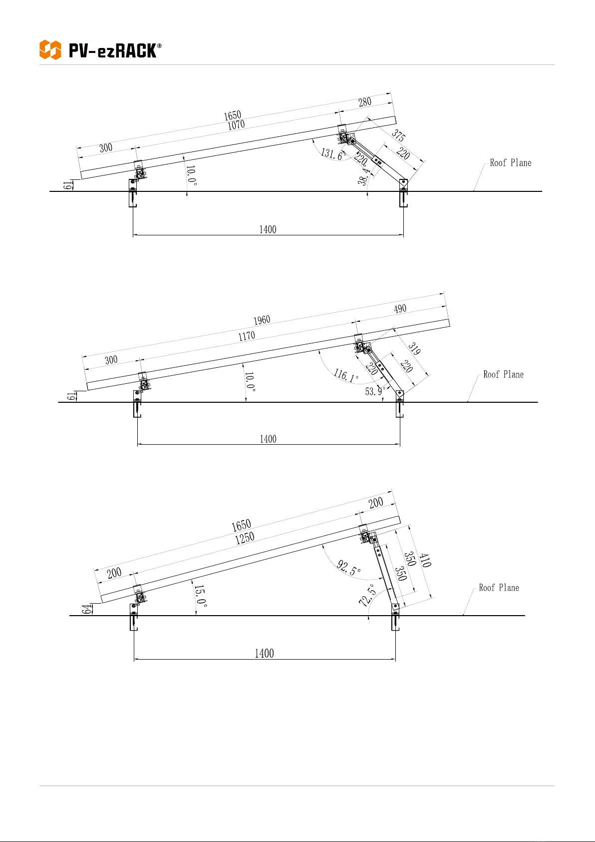
The Clenergy PV-ezRack® SolarRoof Tilt Legs has been
developed as a universal PV-mounting system for
roof-mounting on pitched and flat roofs. The use of
patented aluminium base rails, Z-Module technology
and telescopic mounting technology eliminates custom
cutting and enables fast installation.
Please review this manual thoroughly before installing
PV-ezRack® SolarRoof Tilt Legs.
This manual provides:
1) Supporting documentation for building permit
applications relating to PV-ezRack® SolarRoof Tilt Legs
Universall PV Module Mounting System,
2) Planning and installation instructions.
- Introduction -
The PV-ezRack® SolarRoof Tilt Legs parts, when installed
in accordance with this guide, will be structurally
sound and will meet the AS/NZS1170.2:2011 Amdt
2- 2016 standard. During installation, and especially
when working on the roof, please comply with the
appropriate Occupational Health and Safety regulations.
Please also pay attention to any other relevant State or
Federal regulations. Please check that you are using the
latest version of the Installation Manual, which you can
do by contacting Clenergy Australia via email on sales@
clenergy.com.au, or contacting your local distributor in
Australia.
Product Warranty:
Please refer PV-ezRack® Product Warranty on our
website.

Installation Guide / SolarRoof Tilt Legs
2
Code-Compliant Planning and Installation Guide V 5.1 - Complying with AS/NZS1170.2-2011 AMDT 2-2016
- Planning -
Planning
Determine the wind region of your installation site
Region C areas (64 m/s) are generally referred to as
Cyclonic and are generally limited to northern coastal
areas. Most Region C zones end 100km inland.
Region D (79 m/s) is Australia's most extreme Cyclonic
Region, located between the town of Carnarvon and
Pardoo Station in Western Australia.
•
•
•
•
Wind regions are pre-defined for the whole of Australia by the Australian Standard 1170.2.
The Wind Region is an independent factor of surrounding topography or buildings.
Region Definition
Most of Australia is designated Region A which
indicates a Regional Wind Velocity of 43 m/s with
wind average recurrence of 200 years.
Some areas are designated Region B (52 m/s). Local
authorities will advise if this applies in your area.

Installation Guide / SolarRoof Tilt Legs
3Code-Compliant Planning and Installation Guide V 5.1 - Complying with AS/NZS1170.2-2011 AMDT 2-2016
Determine the Terrain Category
You will need to determine the terrain category to ensure the installation meets the required standard.
Terrain Category 1 (TC1) – Very exposed open terrain with few or no obstructions and enclosed, limited-sized water
surfaces at serviceability and ultimate wind speeds in all wind regions, e.g. flat, treeless, poorly grassed plains; rivers,
canals and lakes; and enclosed bays extending less than 10km in the wind direction.
Terrain Category 1.5 (TC1.5) – Open water surfaces subjected to shoaling waves at serviceability and ultimate wind
speeds in all wind regions, e.g. near-shore ocean water; larger unenclosed bays on seas and oceans; lakes; and
enclosed bays extending greater than 10km in the wind direction. The terrain height multipliers for this terrain category
shall be obtained by the linear interpolation between the values for the TC1 and TC2.
Terrain Category 2 (TC2) – Open terrain, including grassland, with well-scattered obstructions having heights generally
from 1.5m to 5m, with no more than two obstructions per hectare, e.g. farmland and cleared subdivisions with isolated
trees and uncut grass.
Terrain Category 2.5 (TC2.5) – Terrain with a few trees or isolated obstructions. This category is intermediate between
TC2 and TC3 and represents the terrain in developing outer urban areas with scattered houses, or larger acreage
developments with fewer than ten buildings per hectare. The terrain-height multipliers for this terrain category shall be
obtained by linear interpolation between the values for the TC2 and TC3.
Terrain Category 3 (TC3) – Terrain with numerous closely spaced obstructions having heights generally from 3m to 10m.
The minimum density of obstructions shall be at least the equivalent of 10 house sized obstructions per hectare, e.g.
suburban housing or light industrial estates.
Terrain Category 4 (TC4) – Terrain with numerous larger, high (10m to 30m tall) and closely-spaced buildings, such as
large city centers and well-developed industrial complexes.
If your installation site is not at TC 2, 2.5 or 3, please contact Clenergy to obtain a project specific engineering certificate
to support your installation.
Determine the Height of the Installation Site
This document provides sufficient information for the PV-ezRack® SolarRoof Tilt Legs system installation up to heights
of 30 meters. If your installation site is more than 30 meters high please contact Clenergy to obtain project specific
engineering certificate to support your installation.
Determine Roof slope and Tilt Leg Angle
The PV-ezRack® SolarRoof Tilt Legs system is suitable for roof slope up to 22° for rails running perpendicular to the roof
slope (including standard and reverse tilt), and up to 10° for rails running parallel to the roof slope. See the diagrams of
3 different scenarios below.
Please always keep back leg tilt within 30° - 90° from roof plane or horizontal depending on certain scenario.
- Planning -

Installation Guide / SolarRoof Tilt Legs
4
Code-Compliant Planning and Installation Guide V 5.1 - Complying with AS/NZS1170.2-2011 AMDT 2-2016
- Planning -
Standard Tilt – Rails perpendicular to Roof Slope
Reverse Tilt – Rails perpendicular to Roof Slope
Standard Tilt – Rails parallel to Roof Slope

Installation Guide / SolarRoof Tilt Legs
5Code-Compliant Planning and Installation Guide V 5.1 - Complying with AS/NZS1170.2-2011 AMDT 2-2016
Determine the Installation Area of Roof
There are 4 different roof zones for tilt leg installation: Internal Zone, Intermediate Zone, Edge Zone and Corner Zone.
Please see diagrams and steps below to define area of each zone.
Step 1. Determine building height (h), width (b) and length (d).
Step 2. Choose the lowest value between "h", "b x 0.2" and "d x 0.2".
Step 3. The lowest value on Step 2, equates to a.
- Planning -
Application of Adjustable Tilt Legs
Purlin spacing 1200 mm 1400 mm 1700 mm
Product 10° 15° 30° 45° 60° 10° 15° 30° 45° 60° 10° 15° 30° 45° 60°
1650 mm panel
in portrait
ER-TL-10/15 √
(1)
√
(2) ××× √
(6) ×××××××××
ER-TL-15/30 ×××××× √
(8) ××××××××
ER-TL-30/60 × × √
(3)
√
(4) ×××√
(10)
√
(12) ×××√
(14) × ×
1960 mm panel
in portrait
ER-TL-10/15 ××××× √
(7) ×××××××××
ER-TL-15/30 ×××××× √
(9) ××××××××
ER-TL-30/60 ××× √
(5) ×××√
(11)
√
(13) ×××√
(15) × ×
Verify Purlin Properties of Building
Please verify purlin properties of building, which could affect the interface spacing. Tilt legs spacing on in the
certification letter is based on steel purlin G450 1.5 mm thick or 35 mm Timber F7 (Pine). For example, if the steel purlin
is less than 1.5 mm thick, the corresponding reduction factor of interface spacing will be applied. Please refer generic
notes 6-7 for details.

Installation Guide / SolarRoof Tilt Legs
6
Code-Compliant Planning and Installation Guide V 5.1 - Complying with AS/NZS1170.2-2011 AMDT 2-2016
Determine Two Screws or One Screw Installations of Tilt Legs
There are options of using two screws or one screw for installations of adjustable and fixed tilt legs, depending on the
project details, like required support spacing, purlin spacing, rib spacing of roof sheet and so on. Please find both two
screws and one screw engineering certificates at the end of installation guides for max support spacing.
Determine the Maximum Rail Support Spacing
Please refer to the Certification Letter and Tilt Legs Spacing Table. If a project specific Certification Letter has been
provided, please refer to the support spacing in this letter.
Verify Maximum Rail End Overhang
Rail end overhang should not be over 40% of the Tilt Legs spacing. For example, if the Tilt Legs spacing is 1500mm, the
Rail end overhang can be up to 600mm only.
The application of Adjustable Tilt Legs
Following the tilt angle rules of 2.4 on the north or south facing roof, the actual panel tilt angles using the adjustable
tilt legs installed at the different purlin spacing could be applicable or not. Please see the table and side view diagrams
below.
- Planning -
Note: √indicates applicable; ×indicates not applicable
The table above is based on:
1. The panels are clamped within one quarter of panel length;
2. Rear leg adjustable range: ER-TL-10/15: 260-375 mm; ER-TL-15/30: 390-635 mm; ER-TL-30/60: 675-1205 mm;
3. If the info. is different from the table and diagram, it could have different results. Please contact the Clenergy to
confirm its applicability.
Application of Adjustable Tilt Legs
Purlin spacing 1200 mm 1400 mm 1700 mm
Product 10° 15° 30° 45° 60° 10° 15° 30° 45° 60° 10° 15° 30° 45° 60°
1650 mm panel
in portrait
ER-TL-10/15 √
(1)
√
(2) ××× √
(6) ×××××××××
ER-TL-15/30 ×××××× √
(8) ××××××××
ER-TL-30/60 × × √
(3)
√
(4) ×××√
(10)
√
(12) ×××√
(14) × ×
1960 mm panel
in portrait
ER-TL-10/15 ××××× √
(7) ×××××××××
ER-TL-15/30 ×××××× √
(9) ××××××××
ER-TL-30/60 ××× √
(5) ×××√
(11)
√
(13) ×××√
(15) × ×

Installation Guide / SolarRoof Tilt Legs
7Code-Compliant Planning and Installation Guide V 5.1 - Complying with AS/NZS1170.2-2011 AMDT 2-2016 - Planning -
(1)
(2)
(3)

Installation Guide / SolarRoof Tilt Legs
8
Code-Compliant Planning and Installation Guide V 5.1 - Complying with AS/NZS1170.2-2011 AMDT 2-2016
- Planning -
(5)
(4)

Installation Guide / SolarRoof Tilt Legs
9Code-Compliant Planning and Installation Guide V 5.1 - Complying with AS/NZS1170.2-2011 AMDT 2-2016 - Planning -
(6)
(8)
(7)

Installation Guide / SolarRoof Tilt Legs
10
Code-Compliant Planning and Installation Guide V 5.1 - Complying with AS/NZS1170.2-2011 AMDT 2-2016
- Planning -
(9)
(10)

Installation Guide / SolarRoof Tilt Legs
11 Code-Compliant Planning and Installation Guide V 5.1 - Complying with AS/NZS1170.2-2011 AMDT 2-2016 - Planning -
(11)
(12)

Installation Guide / SolarRoof Tilt Legs
12
Code-Compliant Planning and Installation Guide V 5.1 - Complying with AS/NZS1170.2-2011 AMDT 2-2016
- Planning -
(13)
(14)

Installation Guide / SolarRoof Tilt Legs
13 Code-Compliant Planning and Installation Guide V 5.1 - Complying with AS/NZS1170.2-2011 AMDT 2-2016 - Planning -
(15)

Installation Guide / SolarRoof Tilt Legs
14
Code-Compliant Planning and Installation Guide V 5.1 - Complying with AS/NZS1170.2-2011 AMDT 2-2016
Tools and Components
Tools
Screw Driver
(maximum
torque≥34N·m)
String & Marker PenTorque Spanner Socket Wrench M8 5m Tape
- Tools and Components -
Components
ER-R-ECO
ECO-Rail
ER-EC-ST
End Clamp
ER-IC-ST
Inter Clamp
C-U/30/46
Universal Clamp
C-U/30/46-G
Universal Clamp
ER-TL-10/15
ER-TL-15/30
ER-TL-30/60
Adjustable Tilt legs,
non-preassembly
ER-SP-ECO
Splice for ECO-Rail
ER-TL-10/15/PS
ER-TL-15/30/PS
Adjustable Tilt legs,
preassembly
TL-10/15/L/PS
TL-15/30/L/PS
Adjustable Tilt Legs with
L-feet, preassembly
ER-TL-5/PS
ER-TL-10/PS
Fixed Tilt Legs,
preassembly

Installation Guide / SolarRoof Tilt Legs
15 Code-Compliant Planning and Installation Guide V 5.1 - Complying with AS/NZS1170.2-2011 AMDT 2-2016
System Overview
Adjustable Tilt Legs
Adjustable Tilt Legs with L-feet
1. End Clamp 2. Inter Clamp 3. Grounding Clip 4. ECO-Rail 5. Grounding Lug 6. Adjustable Tilt Legs
1. End Clamp 2. Inter Clamp 3. Grounding Clip 4. ECO-Rail 5. Grounding Lug 6. Adjustable Tilt Legs with L-feet
Overview of PV-ezRack® SolarRoof Adjustable Tilt Legs
- System Overview -
①
②
③
④
⑤
⑥
①
②
③④
⑤
⑥

Installation Guide / SolarRoof Tilt Legs
16
Code-Compliant Planning and Installation Guide V 5.1 - Complying with AS/NZS1170.2-2011 AMDT 2-2016
Fixed Tilt Legs
1. End Clamp 2. Inter Clamp 3. Grounding Clip 4. ECO-Rail 5. Grounding Lug 6. Fixed Tilt Legs
- System Overview -
①
②
③
④
⑤
⑥
Precautions during Stainless Steel Fastener Installation
Improper operation may lead to deadlock of Nuts and Bolts. The steps below should be applied to stainless steel nut
and bolt assembly to reduce this risk.
General installation instructions:
(1) Apply force to fasteners in the direction of thread
(2) Apply force uniformly, to maintain the required torque
(3) Professional tools and tool belts are recommended
(4) In some cases, fasteners could be seized over time. As an option, if want to avoid galling or seizing of thread, apply
lubricant (grease or 40# engine oil) to fasteners prior to tightening.

Installation Guide / SolarRoof Tilt Legs
17 Code-Compliant Planning and Installation Guide V 5.1 - Complying with AS/NZS1170.2-2011 AMDT 2-2016 - System Overview -
Safe Torques
Please refer to safe torques defined in this guide as shown in the figure below. If power tools are required, Clenergy
recommends the use of low speed only. High speed and impact drivers increase the risk of bolt galling (deadlock). If
deadlock occurs and you need to cut fasteners, please make sure that there is no load on the fastener before you cut it.
Avoid damaging the anodized or galvanized surfaces.
1) Adjustable Tilt Legs
Note:
Grounding Z Module, External Teeth Lock Washers, Spring washer and corrugated shim (with pins) on the diagram
above are to create the electrical continuity between rail and rear leg tubes.

Installation Guide / SolarRoof Tilt Legs
18
Code-Compliant Planning and Installation Guide V 5.1 - Complying with AS/NZS1170.2-2011 AMDT 2-2016
- System Overview -
2) Adjustable Tilt Legs with L-feet
Note:
Grounding Z Module, External Teeth Lock Washers, Spring washer and corrugated shim (with pins) on the diagram
above are to create the electrical continuity between rail and rear leg tubes.
3) Fixed Tilt Legs
Note:
Grounding Z Module,External Teeth Lock Washer and Spring washer on the diagram above are to create the
electrical continuity between rail and rear leg tubes.

Installation Guide / SolarRoof Tilt Legs
19 Code-Compliant Planning and Installation Guide V 5.1 - Complying with AS/NZS1170.2-2011 AMDT 2-2016
Installation Instructions
Front Leg Installation
According to the installation plan, determine the mounting position and direction of the front legs. Either two screws
or single screw (Buildex 14-11 x 70 Hex Head Zips screw) is required depending on the installation spacing requirement.
See two screws and single screw options in Figures 1 and 2. Tin foot front leg installation is in Figure 3.
- Installation Instructions -
Front & Rear Leg Installation
Figure 2
(Front Leg Installation with Single Screw)
Figure 3
(Tin Foot Front Leg Installation)
Figure 1
(Front Leg Installation with Two Screws)
Please follow Buildex screws installation guide below:
- Use a 3/8" Hex Socket.
- Use a mains powered or cordless screw driver with a drive speed of 3,000 RPM maximum.
- Fit the driver bit into the screw and place at the fastening position.
- Apply consistently firm pressure (end load) to the screw driver until the screw is fastened.
- Screws with bonded washers should be tightened only until the washer is gripped firmly enough to provide a
watertight seal. The screws should be neither under tightened nor over tightened to lead to water penetration.
Take particular care to ensure the screw is driven perpendicular to the interface to avoid deformation of the washer.
Under Tightened Correctly Tightened Over Tightened
This manual suits for next models
2
Table of contents
Other PV-ezRack Construction Equipment manuals
Popular Construction Equipment manuals by other brands

SGS
SGS EC2000 owner's manual

Fayat Group
Fayat Group Dynapac CA25 instruction manual

Meva
Meva MGC-F Technical instruction manual

Weber mt
Weber mt DVH 550 L - 2 Operating and maintenance manual

Haufftechnik
Haufftechnik ESH PolySafe Assembly instructions

Midland
Midland SPD-6 Operation, Parts & Service Manual