manuals.online logo
Brands
  1. Home
  2. •
  3. Brands
  4. •
  5. Pvelectronics
  6. •
  7. Clock
  8. •
  9. Pvelectronics Nixie Large Tube Clock Configuration guide

Pvelectronics Nixie Large Tube Clock Configuration guide

Nixie Tube Clock ‘LTC’
Issue 1 (1 November 2011)
www.pvelectronics.co.uk
- 1 -
Assembly Instructions
And
ser Guide
Nixie Clock Type
‘Large Tube Clock’
Nixie Tube Clock ‘LTC’
Issue 1 (1 November 2011)
www.pvelectronics.co.uk
- 2 -
REVISION HISTORY
Issue
Number
Date Reason for Issue
1 1 November 2011 New document
Nixie Tube Clock ‘LTC’
Issue 1 (1 November 2011)
www.pvelectronics.co.uk
- 3 -
1. INTROD CTION
1.1 About the clock
Nixie clock type ‘LTC’ is comp ct design with ll components nd tubes
mounted on single PCB. The efficient use of bo rd sp ce is chieved by using
multiplex design to drive the displ y tubes. Two high-volt ge bin ry-to-decim l
decoder ICs (K155ID1) re required, driving the six tubes in groups of three.
1.2 Clock Features
Nixie clock type ‘LTC’ h s the following fe tures:
- Hours, Minutes nd Seconds displ y
- 12 or 24 hour modes
- D te displ y in either DD.MM.YY or MM.DD.YY form t
- Al rm, with progr mm ble snooze period
- Progr mm ble d te displ y e ch minute
- Attr ctive LED tube lighting
- Uses Qu rtz Cryst l Oscill tor s the timeb se
- Option l DCF / WWVB / MSF / GPS synchronis tion with st tus indic tor LED
- Superc p citor b ckup. Keeps time during short power out ges
- Simple time setting using two buttons
- Progr mm ble le ding zero bl nking
- Five progr mm ble neon colon settings (Fl shing AM/PM indic tion, illumin ted
AM/PM indic tion, both fl shing, both on, both off)
- M int ins time during setup mode, eg. When ch nging between St nd rd Time
nd D ylight S vings Time
- Seconds c n be reset to zero to precisely the set time
- Progr mm ble night mode - bl nked or dimmed displ y to s ve tubes or
prevent sleep disturb nce
- Sep r te modes for colon neons during night mode
- St nd rd or f ding ch nge of digits
- ‘Slot M chine’ C thode poisoning prevention routine
- All user preferences stored to non-vol tile memory
Nixie Tube Clock ‘LTC’
Issue 1 (1 November 2011)
www.pvelectronics.co.uk
- 4 -
1.3 SAFETY
DANGER: The clock pcb includes switched-mode volt ge booster circuit. This
gener tes nomin lly 170 Volts DC, but is c p ble of gener ting up to 300 Volts
before djustment. Assembly m y only be undert ken by individu ls who re
suit bly qu lified nd experienced in electronics ssembly, nd re f mili r with
s fe procedures for working with high volt ges. If in doubt, refer to suit bly
qu lified engineer before proceeding.
The voltages generated by this circuit can give a potentially LETHAL
ELECTRIC SHOCK.
DISCLAIMER: This product is supplied s kit of p rts, intended only for suit bly
qu lified electronic engineers, who re suit bly qu lified nd experienced in
electronics ssembly, nd re f mili r with s fe procedures for working with high
volt ges. The supplier, his gents or ssoci tes ccept no li bility for ny
d m ge, injury or de th rising from the use of this kit of p rts.
This is not finished product, nd the person ssembling the kit is responsible
for ensuring th t the finished product complies with ny pplic ble loc l
regul tions governing electric l equipment, eg. UL, CE, VDE.
Nixie Tube Clock ‘LTC’
Issue 1 (1 November 2011)
www.pvelectronics.co.uk
- 5 -
2. TOOLS AND EQ IPMENT REQ IRED
2.1 Tools required to assemble the PCB.
The following tools will be required to ssemble the PCB:
- Soldering iron with sm ll tip (1-2 mm)
- Wire cutters (TIP: A sm ll p ir of n il clippers works very well for this
function)
- Wire strippers (TIP: A sm ll p ir of scissors is quite suit ble)
- Multimeter for volt ge tests nd for identifying the resistors.
- Sm ll fl t screwdriver for djusting the high volt ge supply
2.2 Materials you will need.
Solder – le d / tin solder is preferred. Le d free solder, s now required to be
used in commerci l products in Europe, h s much higher melting point nd c n
be very h rd to work with.
Desoldering wick (br id) c n be useful if you ccident lly cre te solder bridges
between dj cent solder joints.
2.3 Other items you will need.
The clock kit does not include power d pter. This is bec use the kit is sold to
m ny countries round the world, e ch with very different household m ins
outlet socket types. It is more efficient for the user to buy suit ble d pter
loc lly. This s ves shipping he vy d pter with the kit, nd lso the extr costs
of m n ging stocks of m ny v ried power d pters. If you re using WWVB,
DCF or MSF receiver void che p Chinese switching power supplies, s they c n
c use interference problems.
The type of power d pter c n be obt ined t very low cost. The following type
of d pter should be obt ined nd used with the kit:
Output 12V DC
Minimum power output c p bility of 500 mA
Output plug: 2.1mm pin, centre positive.
A suit ble d pter is shown below:
Nixie Tube Clock ‘LTC’
Issue 1 (1 November 2011)
www.pvelectronics.co.uk
- 6 -
3. LIST OF COMPONENTS
3.1 Table of components
Circuit Designation Part Description
Resistors
R1 270Ω, ¼ W tt
R2 270Ω, ¼ W tt
R3 4.3KΩ, ¼ W tt
R4 620KΩ, ¼ W tt
R5 4.3KΩ, ¼ W tt
R6, R7 270Ω, ¼ W tt
R8 – R14 4.3KΩ, ¼ W tt
R15- R17 390KΩ, ¼ W tt
R18 – R20 Not inst lled
R21 – R26 390KΩ, ¼ W tt
R27, R28 4.3KΩ, ¼ W tt
R29, R30 390KΩ, ¼ W tt
R37 Not inst lled
R38, R39 270Ω, ¼ W tt
C p citors
C1 470µF, 16-25V, Electrolytic
C2 100 µF, 16-25V, Electrolytic
C3 330pF Cer mic
C4 100nF Cer mic
C5 470 µF, 16-25V, Low ESR
C6 33pF Cer mic
C7 100nF Cer mic
C8 1 µF, 250V, Electrolytic
C9 100nF Cer mic
C10 0.1F
C11 33pF Cer mic
C12 33pF Cer mic
C13 100nF Cer mic
Tr nsistors
Q1 BC639
Q2 BC640
Q3 IRFxxx MOSFET
Q4 – Q7 MPSA42
Q8 – Q10 MPSA92
Q11- Q13 MPSA42
Diodes
D1, D2 1N5819
D3 UF4004
D4 5mm Green LED
D5 5mm Or nge LED
Integr ted Circuits
IC1 7805 5V Volt ge regul tor
IC2 MC34063A
IC3 PIC16F1936 8-bit Microcontroller
IC3, IC4 74141 / K155ID1 Nixie driver
Nixie Tube Clock ‘LTC’
Issue 1 (1 November 2011)
www.pvelectronics.co.uk
- 7 -
Miscell neous
L1 100 µH Axi l inductor
NE1, NE2 6mm Wire ended neon l mp
SW1, SW2, SW3 Mini ture push button
VR1 1K Potentiometer
IC Sockets 8 W y DIP IC socket for IC2
28 W y DIP IC socket for IC3
2 X 16 W y DIP IC sockets for
IC4, IC5
J1 2.1mm PCB Power socket
GPS / RFT 6 W y mini DIN PCB socket
LS1 Piezo sounder
FUSE 500mA Resett ble fuse
Insul tion Cle r insul tion for neons
X1 32.768KHz W tch cryst l
Socket recept cles 66 X 1mm Socket recept cles
Lighting P ck:
The option l p ck cont ins the extr components needed for the tube
underlighting:
Circuit Designation Part Description
R31 – R36 270Ω, ¼ W tt
D6 – D11c 1206 SMD LEDs (18 tot l + 2
sp re)
Blue, Yellow, Green or Purple
Q14 2N7000 MOSFET
The resistors used in the kit re 1% toler nce met l film. They re
m rked with 4 coloured b nds to identify the v lue. However it is
sometimes uncle r in which direction the b nds should be re d.
Therefore, we recommend th t the resistors be identified with
multimeter.
Nixie Tube Clock ‘LTC’
Issue 1 (1 November 2011)
www.pvelectronics.co.uk
- 8 -
3.2 Parts list / Packing sheet
Part Description Quantity
Resistors
270Ω, ¼ W tt 6
4.3KΩ, ¼ W tt 11
390KΩ, ¼ W tt 11
620KΩ, ¼ W tt 1
C p citors
470µF, 16-25V, Electrolytic 2
100µF, 16-25V, Electrolytic 1
1µF, 250V, Electrolytic 1
100nF, Cer mic 4
33pF, Cer mic 3
0.1F 1
330pF, Cer mic 1
Tr nsistors
IRFxxx MOSFET 1
BC639 1
BC640 1
MPSA42 7
MPSA92 3
Diodes
1N5819 2
UF4004 F st recovery diode 1
5mm Green LED 1
5mm Or nge LED 1
Integr ted Circuits
7805 5V Volt ge regul tor 1
MC34063A 1
PIC16Fxxxx 8-bit Microcontroller 1
74141 / K155ID1 Nixie driver 2
Miscell neous
100 µH Axi l inductor 1
6mm Wire ended neon l mp 2
Mini ture push button 3
1K Potentiometer 1
8 W y DIP IC Socket 1
28 W y DIP IC Socket 1
16 W y DIP IC Socket 2
2.1mm PCB Power socket 1
6 W y mini DIN PCB socket 1
Piezo sounder 1
500mA Resett ble fuse 1
6 cm Cle r insul tion 1
32.768KHz w tch cryst l 1
1mm Socket recept cles 66
Nixie Tube Clock ‘LTC’
Issue 1 (1 November 2011)
www.pvelectronics.co.uk
- 9 -
Lighting P ck:
The option l p ck cont ins the extr components needed for the tube
underlighting:
270Ω, ¼ W tt resistor 6
1206 SMD Resistors
Blue, Yellow, Green or Purple
20
2N7000 MOSFET 1
It is recommended th t the kit is checked g inst the lists bove, to
ensure ll p rts re present before commencing ssembly. Don’t be
l rmed if there re some extr components, s some component b gs
re sh red between different kit types. Also check our kit upd tes
document on our website downlo ds p ge. This det ils ny ch nges to
components, or substitutions th t h ve been m de due to p rt
v il bility.
Nixie Tube Clock ‘LTC’
Issue 1 (1 November 2011)
www.pvelectronics.co.uk
- 10 -
4. ASSEMBLY OF THE PCB
NOTE THAT THESE INSTR CTIONS ARE SHARED BETWEEN
SEVERAL VERY SIMILAR CLOCK TYPES. YO R PCB MAY NOT LOOK
EXACTLY LIKE THE ONE PICT RED.
4.1 1mm Sockets For Nixie Tubes
There re 66 individu l sockets th t need to be soldered in. The best
method is s follows. Pl ce ll sockets into the holes, noting th t for e ch
tube there re three holes th t h ve no socket s m rked on the PCB.
When ll sockets h ve been pl ced, pl ce fl t nd h rd object over the
top of the sockets, nd turn the PCB over so you c n solder from the
underside. Be sure to insert the sockets FROM the bottom side of the PCB
– the side with the tube nd m rkings.
Nixie Tube Clock ‘LTC’
Issue 1 (1 November 2011)
www.pvelectronics.co.uk
- 11 -
4.2 Low Voltage Power components:
J1, F SE
D1, D2 - 1N5819
IC1 - 7805
C1 - 470µF
C2 - 100 µF
St rt by inst lling D1 nd D2. Align the white b nd on the components
with the b nd m rked on the PCB.
Proceed to mount the other components of this step. The two c p citors
re pol rised: the longer le d goes in the hole m rked ‘+’. Keep the IC1
mounted vertic l for the moment. It c n be bent over to lower the profile
of the bo rd t the end of ssembly.
The PCB should now look like the picture below:
Nixie Tube Clock ‘LTC’
Issue 1 (1 November 2011)
www.pvelectronics.co.uk
- 12 -
4.2 Testing Stage 1 Power Components.
Identify the test GND, 5V nd 170V test points s shown below.
Plug in the power supply, nd then test using DC voltmeter: Touch the
bl ck probe on the GND test point nd the red probe on the 5V test point.
The volt ge should me sure between 4.9 nd 5.1 Volts. If not, disconnect
power nd check your work. Do not proceed with the ssembly until the
error is corrected. Once the test is completed, disconnect the power.
4.3 High Voltage Generator components.
Socket for IC2
R1, R2 - 270Ω
R3 - 4.3KΩ
R4 - 620KΩ
R5 - 4.3KΩ
Nixie Tube Clock ‘LTC’
Issue 1 (1 November 2011)
www.pvelectronics.co.uk
- 13 -
4.4 Q1 - BC639
Q2 - BC640
C3 - 330pF
C4 - 100nF
C6 - 33pF
C7 - 100nF
4.5 Q3 - IRFxxx
D3 - F4004
L1 - Inductor
C5 - 470µF
C8 - 1µF
VR1 - 1K Pot
4.6 High Voltage Generator Test
- Refer to the w rnings on p ge 4
- Power up the PCB, nd using the GND nd 170V test points, me sure
the high volt ge gener ted. It should be initi lly between 150 nd 190V. -
- Using the VR1 br ss screw, slowly djust the screw until the volt ge is
between 170 nd 175V. Disconnect the power supply.
Nixie Tube Clock ‘LTC’
Issue 1 (1 November 2011)
www.pvelectronics.co.uk
- 14 -
4.7 Sockets for IC3, IC4, IC5
Align the notch on the body of e ch socket with the corrsponding m rk on
the PCB
4.8 R6, R7, R38, R39 (all 270Ω)
R8, R9, R12, R13, R14, R21 - R28 (all 4.3KΩ)
R15, R16, R17, R29, R30 (all 390 KΩ)
4.9 Q5, Q6, Q7, Q11, Q12, Q13 (all MPA42)
Q8, Q9, Q10 (all MPSA92)
Nixie Tube Clock ‘LTC’
Issue 1 (1 November 2011)
www.pvelectronics.co.uk
- 15 -
4.10 X1 - 32.768 KHz Crystal
C11, C12 (33 pF)
These re the timekeeping components: 32.768KHz cryst l nd two lo d
c p citors. See below:
4.11 Tube Test
At this st ge, it is desir ble nd possible to test th t the tube drivers nd
micro-controller re functioning correctly. M king the test t this point,
before the rem ining components re inst lled will m ke troubleshooting
nd di gnosis simpler if there is problem.
Insert IC3 (PIC16F1936) nd IC4, IC5 (both K155ID1) into their sockets.
Be very c reful to lign the notch on the IC body with corresponding PCB
m rkings.
Then insert 6 X IN-18 Nixie tubes into the sockets.
Now power up the PCB, nd the tubes should proceed to ll count in
synchronis tion from 0 to 9 repe tedly. If this does not h ppen, stop nd
check your work c refully before proceeding.
Nixie Tube Clock ‘LTC’
Issue 1 (1 November 2011)
www.pvelectronics.co.uk
- 16 -
4.12 GPS / RFT Connector
LS1 - Piezo sounder
Set, Adj, Alarm Buttons
C10 - 100nF
C9 - 0.1µF Supercapacitor
D4 - Green GPS / RFT LED
D5 - Orange Alarm LED
Note th t if you won't be using R dio Time Receiver Module, then you
c n omit the GPS / RFT Connector nd LED D4.
C9 is pol rised component. The rrows on the component body should
m tch the rrows on the PCB m rking.
If you will be using one of our c ses, lign the 2 LEDs s shown below.
4.13 AM, PM Colon Neon Lamps
The 2 neons c n now be mounted t suit ble height. Use sm ll lengths
of the cle r insul tion supplied on the le ds to prevent shorts.
Nixie Tube Clock ‘LTC’
Issue 1 (1 November 2011)
www.pvelectronics.co.uk
- 17 -
5. OPTIONAL COMPONENTS
5.1 GPS Input Components
If you will be using GPS time receiver module, inst ll the following
components:
GPS / RFT Connector (if you didn't lre dy inst ll it in step 4.12)
R10, R11 (4.3KΩ)
Q4 (MPSA42)
5.3 DCF / WWVB / MSF Receiver Components
If you will be using DCF, WWVB or MSF time receiver module, inst ll the
following component:
C13 - 100nF
5.2 Tube nderlighting Pack
Q14 - 2N7000
R31 – R36 (all 270Ω)
D6A - D11C (18 X 1206 size SMD LEDs)
Three 1206 LEDs per tube provide ttr ctive tube underlighting. St rt by
inst lling Q14 nd the six 270R resistors.
The procedure for inst lling the LEDs is the s me for ll six tube loc tions.
First, identify the white c thode m rks on the PCB s shown below:
Nixie Tube Clock ‘LTC’
Issue 1 (1 November 2011)
www.pvelectronics.co.uk
- 18 -
Now identify the c thode m rk on the LEDs. This is usu lly green
m rking t one end of the LED, though it m y be under the LED lens nd
h rder to see, It m y lso be n rrow or line pointing in one direction
on the underside of the LED:
With fine soldering iron tip, melt sm ll mount of solder onto the
three c thode p ds of the PCB t single tube loc tion:
Using tweezers, pl ce the LED over its p ds nd re- pply the soldering
iron briefly to the p d with the solder on. This will re-melt the solder nd
nchor the LED. Now solder the other p d of the LED.
Repe t this for ll LEDs t e ch tube loc tion, before moving to the next
tube loc tion.
Nixie Tube Clock ‘LTC’
Issue 1 (1 November 2011)
www.pvelectronics.co.uk
- 19 -
6. HOW TO OPERATE THE CLOCK
The three buttons h ve the following functions:
SET: Exit tube test routine on cold power-up;
Show d te;
Set: time, d te;
Enter configur tion menu;
ADJ: C ll WWVB / DCF / MSF;
Adjust: time, d te, l rm time, configur tion p r meters;
ALARM: Set l rm time; snooze; c ncel snooze/ l rm;
Entering configuration mode:
The princip l settings of the clock re stored in fl sh memory – your preferred
configur tion is stored even fter powering off the clock for extended periods.
To ccess the configur tion mode press nd hold the ‘Set’ button. After 2
seconds the seconds will become highlighted. Continue holding the button
further 2 seconds until the clock displ ys in this form t:
00-XX-
99.
The ‘99’ in the seconds digits tells you th t you re in the
configur tion menu.
In configur tion mode the hours digits dipl y the current p r meter being
djusted, nd the seconds digits displ y the current v lue stored g inst the
p r meter.
For e ch p r meter, nd referring to the t ble below, scroll through the r nge
of possible v lues by pressing the ‘ADJ’ button. When the desired v lue h s
been re ched, move on to the next p r meter by pressing the ‘SET’ button.
When the l st p r meter h s been set, pressing ‘SET’ one more time will revert
the clock b ck to time displ y mode. The first p r meter (0) c nnot be ch nged
s it is the softw re revision number. It will show for sever l seconds nd then
move to p r meter 1.
In ll correspondence on support issues, ple se quote the bo rd type, revision
d te nd softw re version.
Nixie Tube Clock ‘LTC’
Issue 1 (1 November 2011)
www.pvelectronics.co.uk
- 20 -
Parameter Description Values
0 Softw re revision 10 = version 1.0, 11 = version 1.1 etc
1 12 / 24 Hr mode 0 – 12 Hr (def ult)
1 – 24 Hr
2 D te form t 0 = MM.DD.YY (def ult)
1 = DD.MM.YY
3 Le ding zero bl nking
eg. 01:54:32
0 – le ding zero bl nked (def ult)
1 – le ding zero displ yed
4 Night mode st rt hour 0 - 23
5 Night mode end hour 0 - 23
6 Night mode 0 – Tubes off
1 – Dimmed displ y (def ult)
7 Displ y mode 0 – st nd rd ch nge of digits
1 – f ding digits (def ult)
8 Night mode override
period (minutes)
0 – 50
(def ult 0 gives 15
seconds override)
1
9 Snooze period 0 – 6 minutes (def ult)
1 – 9 minutes
2 – 12 minutes
3 – 15 minutes
10 Colon neons mode 0 – AM/PM Indic tion, fl shing
1 – AM/PM Indic tion, illumin ted
2 – Both fl sh (def ult)
3 – Both illumin ted
4 – Both off
11 Colon neons during
night dimmed mode
2
0 – AM/PM Indic tion, fl shing
1 – AM/PM Indic tion, illumin ted
2 – Both fl sh
3 – Both illumin ted (def ult)
4 – Both off
12 R dio time sign l
source
0 – No R dio Time source (def ult)
3
1 – DCF
2 - WWVB
3 – MSF
4 - GPS
13 GPS B ud r te 0 – 4.8 Kbps (def ult)
1 – 9.6 Kbps
2 – 19.2 Kbps
3 – 38.4 Kbps
14 R dio time offset hours 0-13 (def ult 0)
4
15 R dio time offset mins 0-45 (def ult 0)
4
16 R dio time offset
pol rity
0 - minus time (def ult)
1 – plus time
17 WWVB Auto DST
Dis ble /Set DST in
GPS mode
WWVB Sync Mode:
0 –Auto DST on WWVB Sync (def ult)
1 – Dis ble Auto DST on WWVB Sync
5
GPS Sync Mode:
0 – No DST offset
1 – 1 hour DST offset
6
18 Auto d te displ y e ch
minute
0 – Off
1 – On (def ult)
7
19 Reserved – le ve s 0 0
20 Reserved – le ve s 0 0

Other Pvelectronics Clock manuals

Pvelectronics Nixie QTC Plus Configuration guide

Pvelectronics

Pvelectronics Nixie QTC Plus Configuration guide

Pvelectronics Halo Clock Configuration guide

Pvelectronics

Pvelectronics Halo Clock Configuration guide

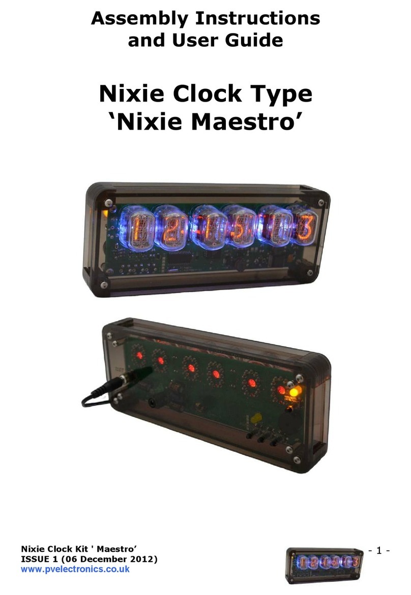
Pvelectronics Nixie Maestro Configuration guide

Pvelectronics

Pvelectronics Nixie Maestro Configuration guide

Pvelectronics Quattro Configuration guide

Pvelectronics

Pvelectronics Quattro Configuration guide

Pvelectronics Frank 2 IN-16 Configuration guide

Pvelectronics

Pvelectronics Frank 2 IN-16 Configuration guide

Pvelectronics Spectrum 18 Configuration guide

Pvelectronics

Pvelectronics Spectrum 18 Configuration guide

Pvelectronics Dink Configuration guide

Pvelectronics

Pvelectronics Dink Configuration guide

Pvelectronics Spectrum 1040 Quick start guide

Pvelectronics

Pvelectronics Spectrum 1040 Quick start guide

Pvelectronics Nixie QTC User manual

Pvelectronics

Pvelectronics Nixie QTC User manual

Pvelectronics SN-18 Configuration guide

Pvelectronics

Pvelectronics SN-18 Configuration guide

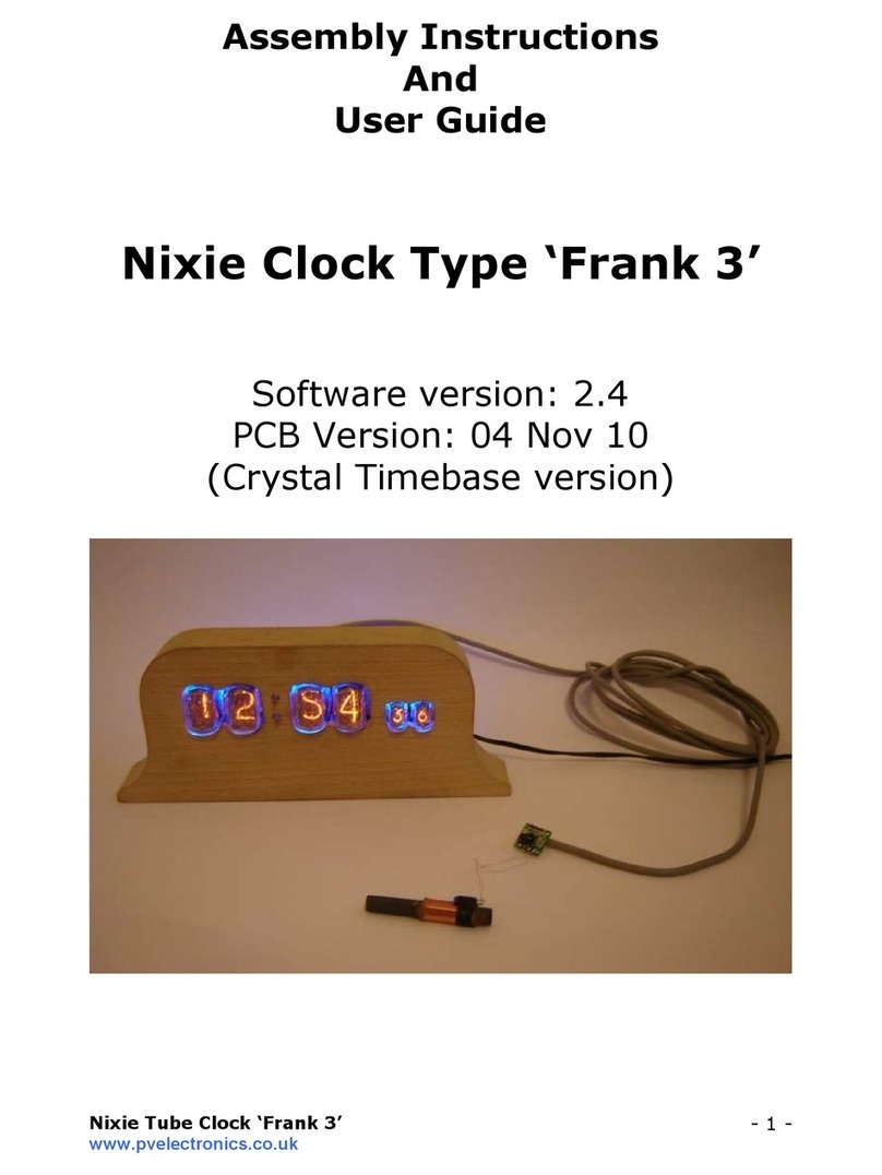
Pvelectronics Frank 3 Configuration guide

Pvelectronics

Pvelectronics Frank 3 Configuration guide

Pvelectronics Frank 3 Configuration guide

Pvelectronics

Pvelectronics Frank 3 Configuration guide

Pvelectronics Halo Chroma Configuration guide

Pvelectronics

Pvelectronics Halo Chroma Configuration guide

Pvelectronics WiFi NTP Sync Device User manual

Pvelectronics

Pvelectronics WiFi NTP Sync Device User manual

Pvelectronics IN-8 Configuration guide

Pvelectronics

Pvelectronics IN-8 Configuration guide

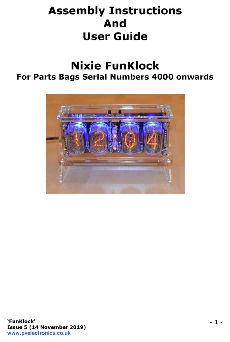
Pvelectronics Nixie FunKlock Configuration guide
Pvelectronics

Pvelectronics Nixie FunKlock Configuration guide

Pvelectronics Frank 3 Configuration guide

Pvelectronics

Pvelectronics Frank 3 Configuration guide

Pvelectronics Nixie Maestro Configuration guide

Pvelectronics

Pvelectronics Nixie Maestro Configuration guide

Pvelectronics Frank 3 Configuration guide

Pvelectronics

Pvelectronics Frank 3 Configuration guide

Pvelectronics Nixie QTC-Four Configuration guide

Pvelectronics

Pvelectronics Nixie QTC-Four Configuration guide

Pvelectronics Elite Nixie Configuration guide

Pvelectronics

Pvelectronics Elite Nixie Configuration guide

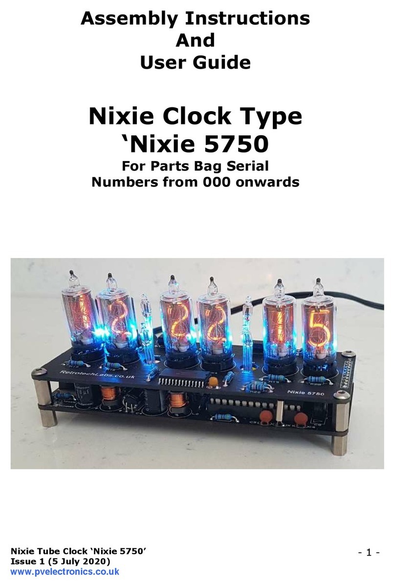
Pvelectronics Nixie 5750 Configuration guide
Pvelectronics

Pvelectronics Nixie 5750 Configuration guide

Popular Clock manuals by other brands

DGT Projects dg2000 Instructions for use

DGT Projects

DGT Projects dg2000 Instructions for use

Fadisol C-0526 manual

Fadisol

Fadisol C-0526 manual

QLOCKTWO 180 Instructions for use

QLOCKTWO

QLOCKTWO 180 Instructions for use

Skyworks Si4822-DEMO user guide

Skyworks

Skyworks Si4822-DEMO user guide

U-Line H-2812 Operation manual

U-Line

U-Line H-2812 Operation manual

Enmac Quran CQC400 user manual

Enmac

Enmac Quran CQC400 user manual

Pyramid TTEZ TIMETRAX EZ quick start guide

Pyramid

Pyramid TTEZ TIMETRAX EZ quick start guide

La Crosse Technology WS-9412 instruction manual

La Crosse Technology

La Crosse Technology WS-9412 instruction manual

Auriol Z30237B Operation and safety notes

Auriol

Auriol Z30237B Operation and safety notes

GINGKO Click Clock Cube manual

GINGKO

GINGKO Click Clock Cube manual

CAPTELEC H1002 quick start guide

CAPTELEC

CAPTELEC H1002 quick start guide

Fysic FKW-6 user manual

Fysic

Fysic FKW-6 user manual

Alecto AK-30 user manual

Alecto

Alecto AK-30 user manual

Pepperl+Fuchs ecom Ex-Time 40 operating instructions

Pepperl+Fuchs

Pepperl+Fuchs ecom Ex-Time 40 operating instructions

MFJ MFJ-122 operating instructions

MFJ

MFJ MFJ-122 operating instructions

Adler AD 1186 user manual

Adler

Adler AD 1186 user manual

Velleman WC30D5 user manual

Velleman

Velleman WC30D5 user manual

Davtron MB800 quick guide

Davtron

Davtron MB800 quick guide

manuals.online logo
manuals.online logoBrands
  • About & Mission
  • Contact us
  • Privacy Policy
  • Terms and Conditions

Copyright 2025 Manuals.Online. All Rights Reserved.