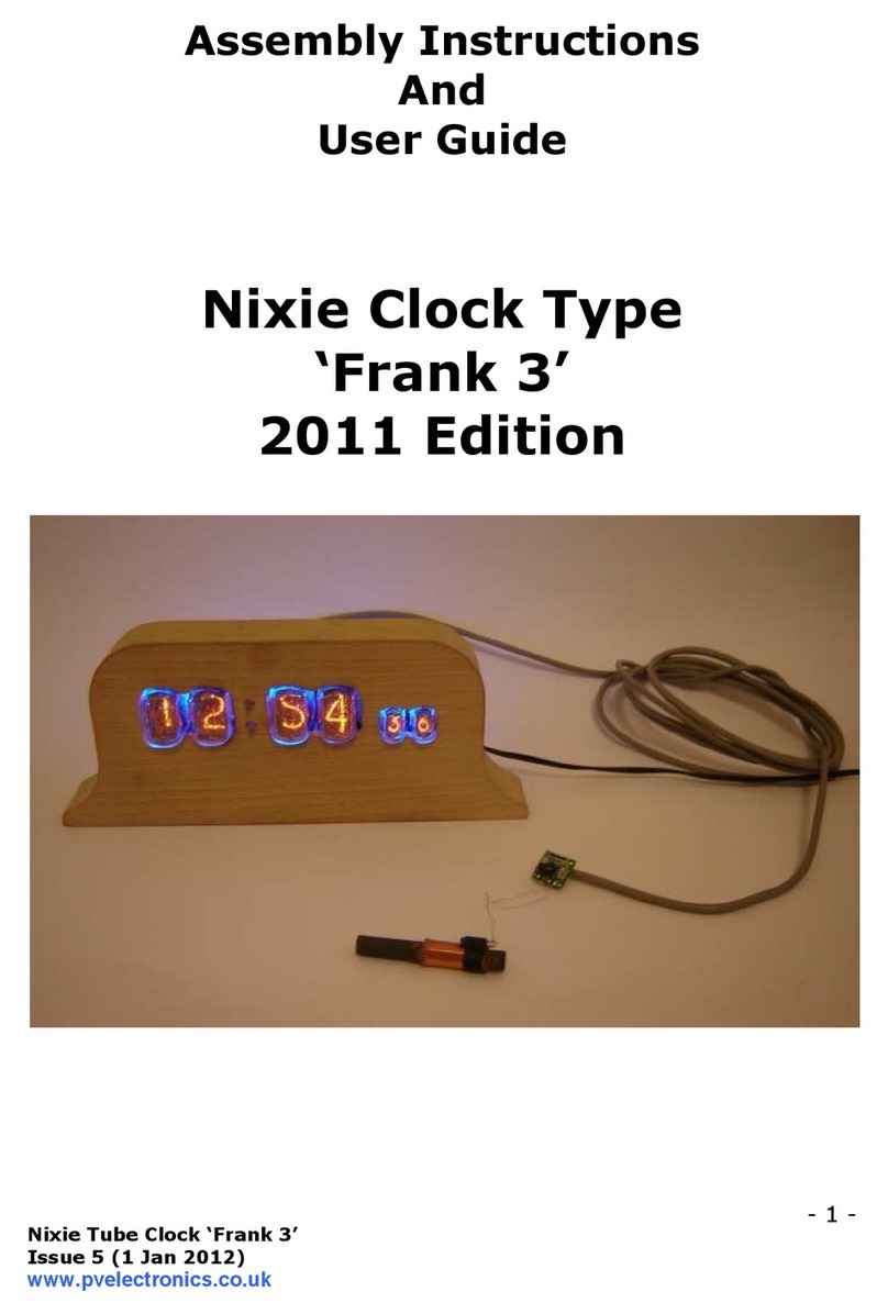
Nixie Clock ‘Frank 3’
- 2 -
Table of Contents
1. IN RODUC ION ................................................................3
1.1 About the clock...............................................................3
1.2 Clock features.................................................................3
1.3 Safety ...........................................................................4
2. OOLS AND EQUIPMEN REQUIRED
...............................
5
2.1 ools required to assemble the PCB...................................5
2.2 Materials you will need ....................................................6
2.3 Other items you will need ................................................6
3. LIS OF COMPONEN S .......................................................6
3.1 able of components .......................................................6
3.2 Parts list
.................................................................
7
3.3 How to identify the correct components .............................8
4. ASSEMBLY OF HE PCB ......................................................9
4.1 Diodes D1-D4 .................................................................9
4.2 Diode D5 .......................................................................9
4.3 IC2 and C3.....................................................................9
4.4 IC1 and Q1 .................................................................. 10
4.5 C1, C2 and C5 .............................................................. 10
4.6 R1, R2, R3, R5, R6 ........................................................ 10
4.7 Variable resistor VR1 ..................................................... 11
4.8 MOSFE Q2 .................................................................. 11
4.9 Inductor L1 .................................................................. 12
4.10 esting the 170V and 5V power supplies ........................ 12
4.10.1 Making up the Power Input Cable ............................... 12
4.10.2 esting the power supplies ........................................ 14
4.11 Socket for IC3, IC4...................................................... 14
4.12 R28, C6, D6................................................................ 14
4.13 Q3-Q8, Q9-Q14, R7-R24 .............................................. 15
4.14 1mm Nixie ube Sockets .............................................. 15
4.15 R25 ........................................................................... 15
4.16 Nixie ubes IN-17 ....................................................... 15
4.17 SW1, SW2.................................................................. 16
4.18 Wire Link.................................................................... 16
5. FINAL ES ING OF PCB.................................................... 17
6. HOW O OPERA E HE CLOCK ......................................... 18
7. CIRCUI DIAGRAM .......................................................... 20
8. DIMENSIONED DRAWING ................................................ 21
