PVI VuMATRIX HD60-4K30 User manual

VuMATRIX
HD60-4K30
HDMI OVER IP FULL HD MATRIX
MANUAL

• Important Safety Instructions
1. Please read the user manual carefully before use this product,
and keep these instructions.
2. Do not mix up transmitter and receiver before installation.
3. Channel of the transmitter(TX) must be different, otherwise, the
system would be breakdown (including transmitter, receiver, IGMP
switch etc.).
4. It is advised to set channel of transmitter before access to switch.
5. Follow all instructions.
6. This extender must be installed and operated within the limits of
specified operating temperature and humidity.
7. Do not place objects on top of the unit.
8. Do not position the matrix extender near any heating source such
as heater, radiator, or direct exposure to sun.
9. Prevent entering of water and moisture into the unit. If necessary,
use dehumidifier to reduce humidity.
10. This product must be used with the IGMP switch.
11. Use DC5V/2A power supply only. Make sure the specification
matched if using 3rd party DC adapters.

• Product Introduction
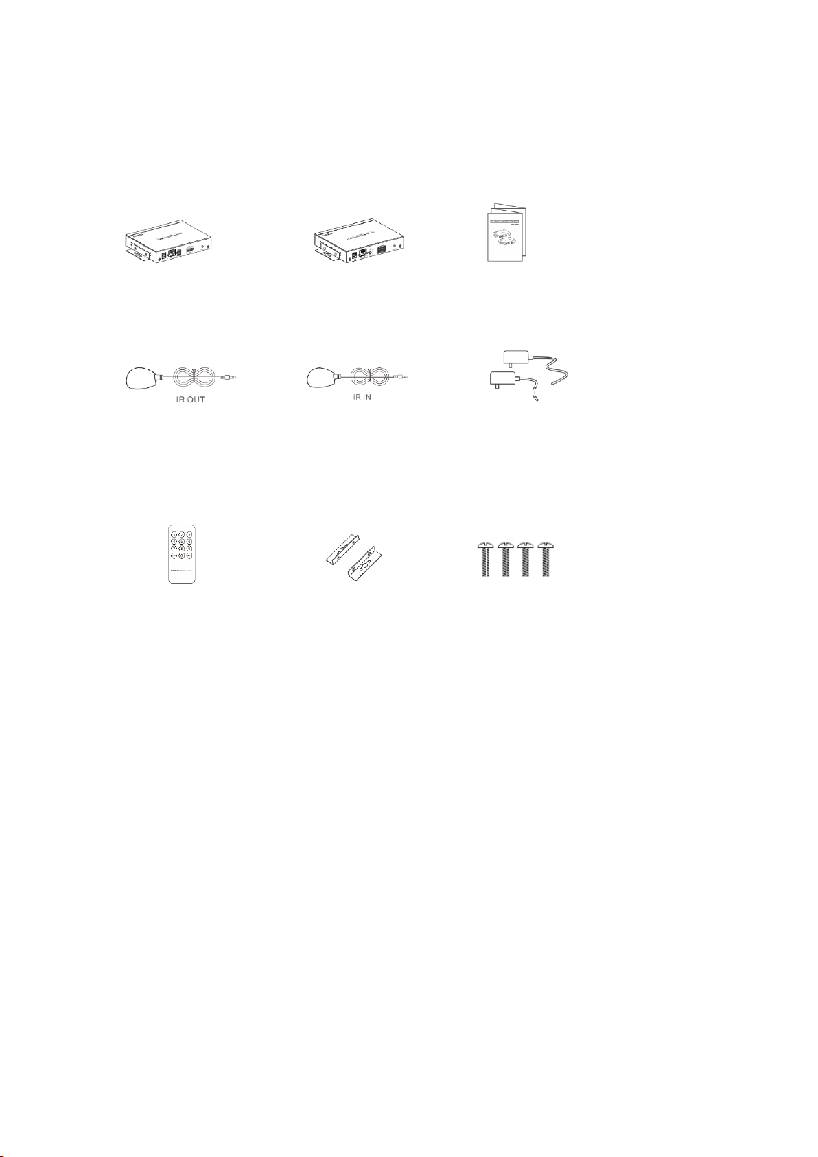
This KIT includes a transmitter unit(TX)
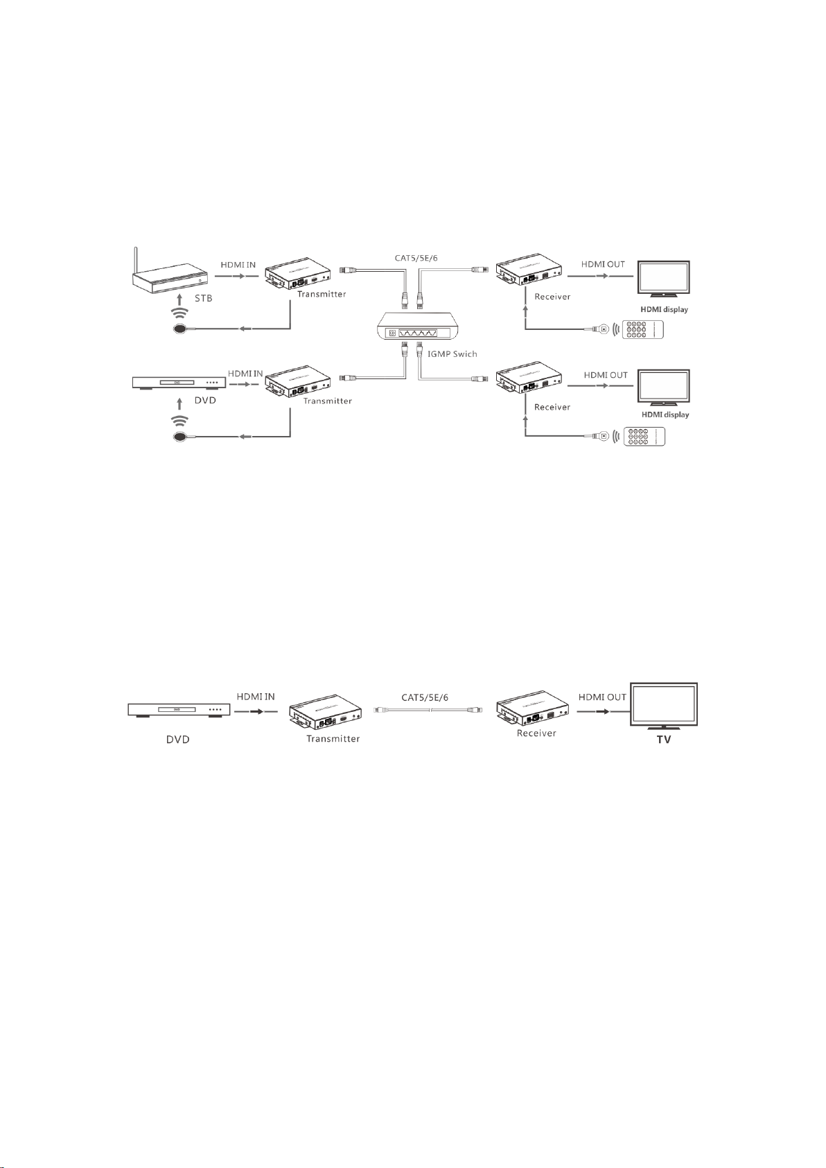
and a receiver unit(RX). It allows for the distribution and switching of
high definition video/audio signal by this product and off-the-shelf IGMP
switch. It applied advanced HDbitT technology, the resolution supported is
up to 4K×2K@30Hz ultra HD. It can also used in a point-to-point
connection, the distance is up to 120 meters. It is widely applied in digital
signage advertisement, control room, command centers, entertainment and
exhibition center, safety monitoring system, etc.
• Product Features
1. Apply advanced HDbitT over IP technology.
2. Resolution supported is up to 4K×2K@30Hz ultra HD.
3. Transmission distance is up to 120 meters via CAT6.
4. Support IR pass back function to control source device from RX
location.
5. Plug and play.
6. Support scalable and flexible input-output matrix configuration,
allows 100 inputs to infinite output.
7. Support computer control software to select and switch source
device input.
8. Support to select and switch source device input from receiver via
remote control and hard button.
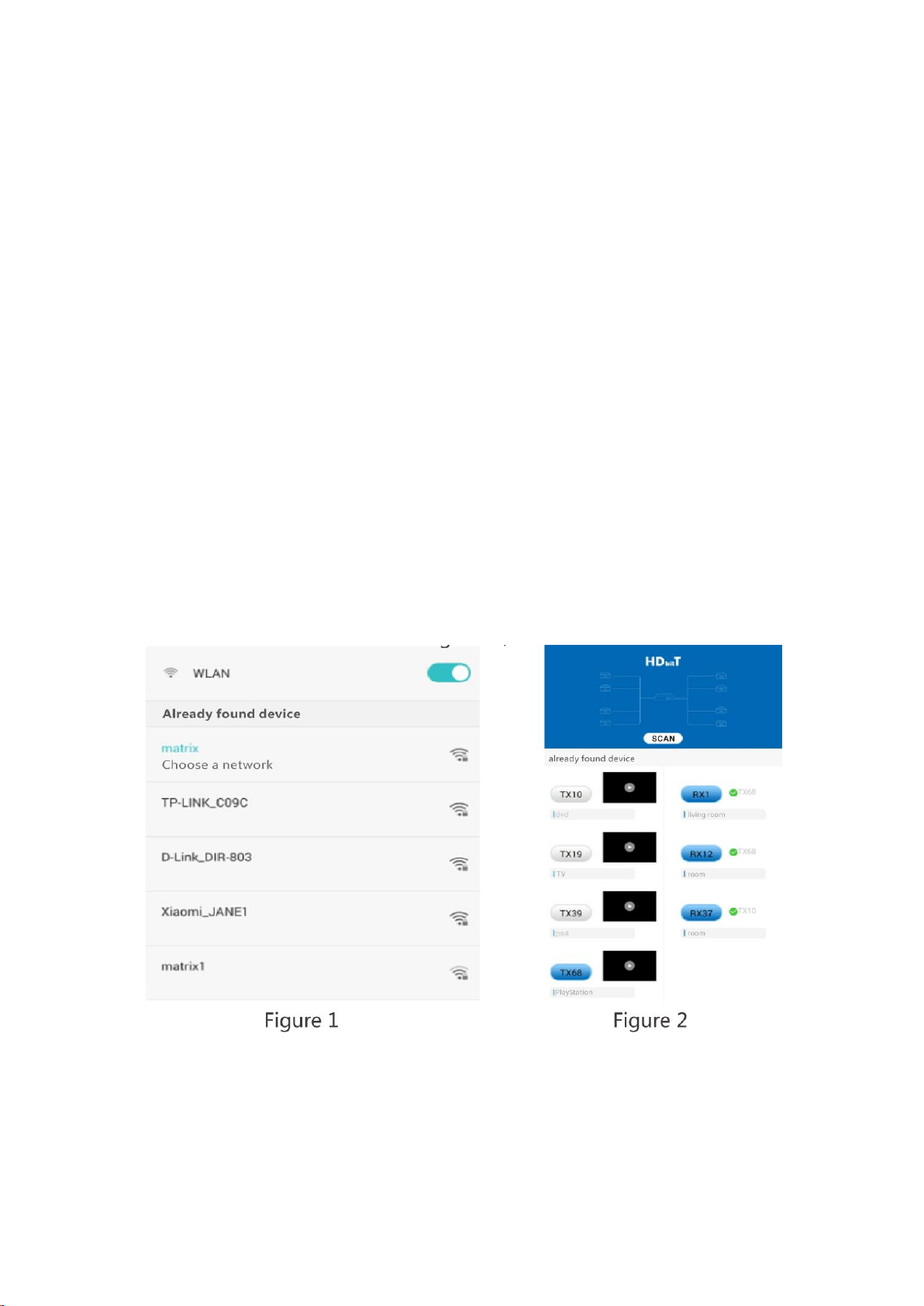
9. Support APP control, user can scan, preview, build up their
configuration by using a phone/tablet easily.

• Package Content
Transmitter unit ×1pcs User manual ×1pcs Receiver unit ×1pcs
IR blaster extension IR receiver extension Power supply
cable x1pcs cable x1pcs (DC5V) ×2pcs
Remote control ×1pcs Wall-mount kit ×4pcs Screws ×8pcs
• Installation Requirements
1. HDMI source devices: with HDMI OUTPUT interface, DVD, PS3, STB, PC etc.
2. Display devices:With HDMI INPUT port, SDTV, HDTV, projector etc.
3. Network cables:
UTP/STP CAT5/5E/6 network cables, which following the standard of IEEE-568B.
Transmission length: CAT5 80m/CAT5E 100m/CAT6 120m.

• Panel Description
1. Transmitter unit

2. Receiver unit
• Installation and Connection
1. How to make a CAT5/5E/6 network cable
Follow the standard of IEEE-568B:
1. white and orange; 2. orange; 3. white and green;
4. blue; 5. white and blue; 6. green;
7. white and brown; 8. brown.

2. Connection Drawing
2.1 Matrix configuration
【NOTE】: The switch must support IGMP function
2.2 Point to point configuration

3. IR use guide
3.1 IR passback
IR blaster extension cable should plug into the IR-out port of TX
(Transmitter) of this extender matrix, and the IR receiver extension
cable should plug into the IR-in port of the RX (Receiver) of this
matrix extender. The emitter of IR blaster should as close as possible
to the IR receiver window of the signal source device.
3.2 IR remote control
Using the IR remote controller to set/select the channel of this
HDMI video Matrix

4. APP control use guide
4.1 HDbitT Matrix Controller MODE--APP “Matrix controller”
4.1.1 Android User: Download the App from our pvisupport site by searching VUMATRIX APP
ANDROID
IOS User: Download the APP"Matrix Controller" from the APP Store.
4.1.2 Firstly, connect the video matrix controller to the IGMP switch.
Then, connect mobile phone/tablet and the video matrix controller
via hotspot"MATRIX" with each other(as figyre 1, the wifi password is
12345678). At this time, open the downloaded APP"matrix control,
will enter to the interface as figure 2, and APP control starts.

4.1.3 APP function
4.1.3.1 Preview
Click ”play”button to preview the content of the source device.

4.1.3.2 Edit
Click the frame under the TX/RX button to edit device name.

4.1.4 Push and slide
Drag push button TX and slide to RX, to set up new connection.
Note: Please do not use more than one mobile phone/tablet to control
the system simultaneously.

5. Button control
There is a “TX ID”on TX unit, and there are both ”RX ID”and “TX connected”
on the RX unit. Each of them consists of two Nixie tubes and two buttons
(beside the Nixie tube), the left button controls the value of the left Nixie tube, and the right one
to control the value of the right Nixie tube. The value of each Nixie tube is from 0 to 9, each
button is pressed at a time, the number is added one value. For example, the existing value of TX
ID is “00”, and press the left button once, also press the right button once, then the value of TX
ID is changed to”11” . When the value of “TX connected” on the RX unit is as same as the
value of “TX ID” on the TX unit, a connection built between the TX and RX units.
Short press: Press to set IGMP group and display the setted value. Product switches
automatically to the corresponding IGMP group 5 seconds after the press.
Long press: Press and keep 3 seconds to reset the product.

6. Computer software control use guide
The WINDOWS APP can be downloaded from our support site www.pvisupport.com searching for
VUMATRIX WINDOWS APP
6.1 Access to network
Connect your PC/computer with the off-the-shelf IGMP
Ethernet switch via a single network cable
6.2 PC/computer setting
Change the PC/computer's IP to 192.168.1.xxx
(xxx can be 0 to 255) , which as same as the IP segment of TX
unit and RX unit.
6.3 Web operation
Open application program “HDbitT E-Matrix Control center”,it
displays the interface as Figure 1( Download from the website:
http://www.hdbitt.com/download-matrix/).

IP setting
TX and RX have their own default IP address, TX's IP is 192.168.1.238, and RX's IP is
192.168.1.239. Generally, it is no need to change the device IP address, as the system can work
normally even though multiple TX units and multiple RX units connected into the system
with their default IP address.

If IP setting is really needed, please follow up the operation as Figure 2 (here make an example of
TX's IP setting only, RX's setting is the same as TX's )
Device scanning and setting (here make an example of TX's setting
only, RX's setting is same as TX's)

* Click button “Start Scan”, the scanned result shows as Figure 3

* Device Name setting as Figure 4

* Device channel (TX ID) setting as Figure 5
Click button “Update”, new configuration saved Pre-operation mode editing , show as Figure
6

Operation mode selection setting
Follow up Figure 7, Click button “Select Mode”, to choose the
mode needed.
Table of contents
Other PVI Matrix Switcher manuals