Q Imaging Retiga ELECTRO User manual

USER MANUAL
DIGITAL IMAGING MADE EASY
www.QIMAGING.com

www.qimaging.com ©2017 QImaging. All rights reserved. 58-608-007 REV A00
RETIGA ELECTRO™USER MANUAL
Applicability
This document applies to the QImaging Retiga ELECTRO camera. For the latest updates, please visit
www.qimaging.com.
Notice of Copyright
Copyright © 2017 Quantitative Imaging Corporation. All rights reserved. Unauthorized duplication of this
document is prohibited.
Trademarks and Proprietary Names
QImaging and Retiga ELECTRO are trademarks of QImaging. PVCAM® is a registered trademark of Roper
Scientific, Inc. Product names mentioned in this document may be trademarks or registered trademarks of
QImaging or other hardware, software, or service providers and are used herein for identification purposes
only. Microsoft® and Windows® are registered trademarks in the U.S. and other countries of Microsoft
Corporation and are used herein for identification purposes only.
QImaging Corporation Address Information
19535 56th Avenue,
Suite 101
Surrey, BC, Canada V3S 6K3
+1.604.530.5800
www.qimaging.com
QImaging Technical Support
Technical support is available to all registered users of QImaging products from 6am to 5pm Pacific Standard
Time.
+1.800.874.9789
http://www.qimaging.com/support/contact

www.qimaging.com ©2017 QImaging. All rights reserved. 58-608-007 REV A00
RETIGA ELECTRO™USER MANUAL
QIMAGING LIMITED WARRANTY
Standard Product Warranty Plan
A Standard Product Warranty Plan is included with every QImaging camera purchase. This Warranty Plan
includes parts and labor for two full years (starting from the shipping date of the camera). The Standard
Product Warranty Plan is provided on all new and used equipment, including retired demonstration cameras.
Extended Product Warranty Plan
Extended Product Warranty Plans are reasonably priced and very easy to purchase. Available for all QImaging
cameras currently under warranty, the Extended Product Warranty Plan includes parts and labor, and is
available for an additional three-year period to extend your warranty to five years.
When you purchase an Extended Product Warranty Plan from QImaging, you are assured of our commitment
to minimizing down times. Your needs are our top priority and QImaging responds immediately. The QImaging
Service and Support team is focused on expediting all customer requests to provide a fast and complete
solution.
QImaging also offers on-site training as well as online operational training programs. These programs are
designed to get you up and running with your new camera quickly and efficiently.
Contact a QImaging Representative to learn more about Extended Product Warranty Plan options.

www.qimaging.com ©2017 QImaging. All rights reserved. 58-608-007 REV A00
RETIGA ELECTRO™USER MANUAL
Table of Contents
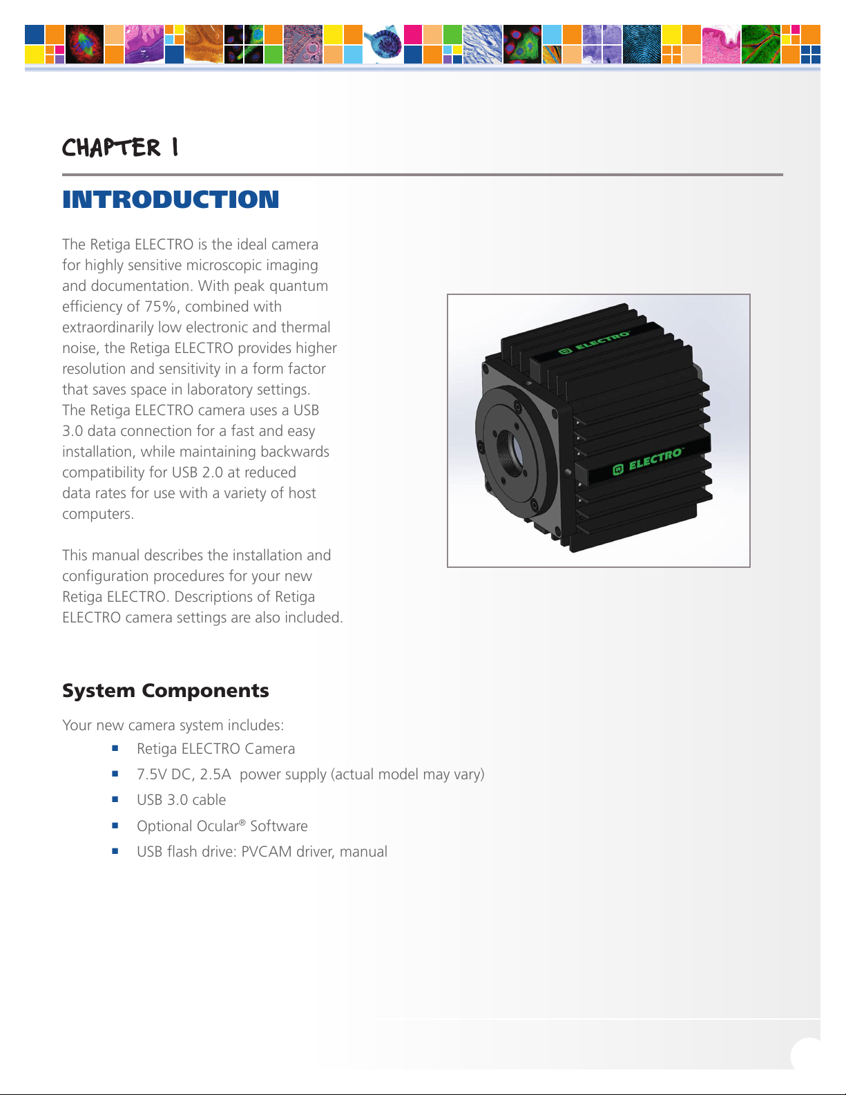
INTRODUCTION ............................................................................................................. 1
System Components .........................................................................................................1
Precautions ........................................................................................................................2
Environmental Conditions for Operation and Storage.........................................................2
Optics and Mounting .........................................................................................................2
Cleaning ............................................................................................................................3
Repair ................................................................................................................................3
INSTALLATION ............................................................................................................... 4
Host Computer Requirements ............................................................................................4
Camera Power Requirements .............................................................................................5
Install the Camera Driver .................................................................................................... 5
Connect the Camera..........................................................................................................5
Note on Selecting the Optimal USB 3.0 Port ....................................................................... 6
Note on Optimum Mounting of Retiga ELECTRO Camera...................................................8
USING YOUR RETIGA ELECTRO CAMERA ..................................................................... 9
Imaging Software...............................................................................................................9
Basic Camera Parameters ...................................................................................................9
Exposure Time....................................................................................................................9
Gain State..........................................................................................................................9
Sensor Cooling.................................................................................................................10
Clearing Mode.................................................................................................................10
ROI / Binning....................................................................................................................11
Device Synchronization ...................................................................................................11
Trigger-First Mode ............................................................................................................ 11
Bulb Mode.......................................................................................................................12
Recommended Initial Settings .........................................................................................13
Embedded Image Processing Algorithms ..........................................................................14
Defective Pixel Correction................................................................................................. 14
TROUBLESHOOTING .................................................................................................... 15
Resolving Problems with the Camera................................................................................ 15
Unresolved Problems - Contacting QImaging Support ...................................................... 17
SPECIFICATIONS ........................................................................................................... 18

www.qimaging.com ©2017 QImaging. All rights reserved. 58-608-007 REV A00 1
RETIGA ELECTRO™USER MANUAL
CHAPTER 1
INTRODUCTION
The Retiga ELECTRO is the ideal camera
for highly sensitive microscopic imaging
and documentation. With peak quantum
efficiency of 75%, combined with
extraordinarily low electronic and thermal
noise, the Retiga ELECTRO provides higher
resolution and sensitivity in a form factor
that saves space in laboratory settings.
The Retiga ELECTRO camera uses a USB
3.0 data connection for a fast and easy
installation, while maintaining backwards
compatibility for USB 2.0 at reduced
data rates for use with a variety of host
computers.
This manual describes the installation and
configuration procedures for your new
Retiga ELECTRO. Descriptions of Retiga
ELECTRO camera settings are also included.
System Components
Your new camera system includes:
■Retiga ELECTRO Camera
■7.5V DC, 2.5A power supply (actual model may vary)
■USB 3.0 cable
■Optional Ocular®Software
■USB flash drive: PVCAM driver, manual

www.qimaging.com ©2017 QImaging. All rights reserved. 58-608-007 REV A00 2
RETIGA ELECTRO™USER MANUAL
Precautions
The Retiga ELECTRO system electronics are extremely sensitive to electrostatic discharge (ESD). To avoid
permanently damaging the system, please observe the following precautions:
■If you are using high-voltage equipment (such as an arc lamp) with your camera system, be sure to
turn the camera power on last and power the camera off first.
■Never connect or disconnect any cable while the camera system is powered on.
■Although you should turn off the camera’s power supply before disconnecting any camera system
cable, you do not need to power off your computer to detach the cables.
■Use caution when triggering high-current switching devices (such as an arc lamp) near your system.
The image sensor can be permanently damaged by transient voltage spikes. If electrically noisy
devices are present, an isolated, conditioned power line or dedicated isolation transformer is highly
recommended.
■Always leave at least one inch of space around the camera housing.
■Never open the camera. There are no user-serviceable parts inside the Retiga ELECTRO camera.
Opening the camera voids the warranty.
■Use only the USB 3.0 interface, cables, and power supply designated for this camera system. Using
non-Retiga ELECTRO cables or power supplies may result in permanent damage to your system.
■Do not use a C-mount lens that has optics that extend behind the flange of the lens.
Environmental Conditions for Operation and Storage
Your Retiga ELECTRO camera system should be operated in a clean, dry environment. The camera system’s
ambient operating temperature is 0°C to 30°C with 80% relative humidity, noncondensing. Contact QImaging
customer service for information if operating outside of this range.
To protect your Retiga ELECTRO during storage, use its original containers. To protect the system from excessive
heat, cold, and moisture, store at an ambient temperature between -20°C and 60°C with a relative humidity of
0% to 90%, noncondensing.
Optics and Mounting
The Retiga ELECTRO camera lens mount accepts a standard 1” diameter, C-mount lens or adapter. The camera
is also compatible with a standard C-mount lenses as long as its optics do not extend behind the flange of the
lens.
If desired, the Retiga ELECTRO may be mounted to a tripod or other device using the mounting attachment
located on each side of the camera’s front plate. See the Specifications chapter for more information.

www.qimaging.com ©2017 QImaging. All rights reserved. 58-608-007 REV A00 3
RETIGA ELECTRO™USER MANUAL
Cleaning
Clean the exterior surfaces of the camera with a dry, lint-free cloth. To remove stains, contact QImaging
Support. To clean the camera’s imaging window, use only a filtered compressed-air source. Handheld cans are
not recommended, as they may spray propellant onto the window. Do not touch the window.
Repair
The Retiga ELECTRO contains no user-serviceable parts. Repairs must be done by QImaging. Should your
camera system need repair, contact QImaging Support. Please save the original packing materials so you can
safely ship the camera system to another location or return it for repairs if necessary.
IMPORTANT: DO NOT OPEN the camera. Opening the Retiga ELECTRO camera voids the warranty.

www.qimaging.com ©2017 QImaging. All rights reserved. 58-608-007 REV A00 4
RETIGA ELECTRO™USER MANUAL
CHAPTER 2
INSTALLATION
This chapter will detail the proper installation of your Retiga ELECTRO camera. In order to install and use the
camera, the following items are required:
■Retiga ELECTRO camera (supplied)
■USB 3.0 data cable (supplied)
■7.5V DC, 2.5A power supply (supplied)
■USB PVCAM Driver “installer” (supplied and also available on the QImaging website)
■110V/220V power connection
■A PVCAM compatible imaging application, such as Ocular (optional)
■A PC that meets host computer requirements
Optional items that are included with your Retiga ELECTRO camera:
■Trigger cable
Host Computer Requirements
The host computer for your Retiga ELECTRO camera must include:
■Windows 7, Windows 8 or Windows 10 operating system (64 bits)
Refer to the QImaging website for the latest list of minimum computer recommendations
■2.0 GHz or faster Intel processor: either Xeon or Core i5
■4+ GB RAM
■250+ GB serial ATA (SATA) HDD and/or >64 GB solid state drive (SDD) for high-speed imaging and
storage
■256+ MB slot-based ATI/NVIDIA video graphics card (i.e., not an “onboard/integrated graphics”
adapter)
■USB port or Internet access to install the driver
■At least one USB 3.0 interface port (USB2.0 is supported, but at reduced frame rate)
NOTE: Minimum requirements as of December 2015. Supported computer systems will change as new
cameras, computer hardware, and operating systems are introduced and older models then become obsolete.
For current information on recommended computer specifications, please visit:
http://www.qimaging.com/support/computer-specs
NOTE: The Retiga ELECTRO camera will also operate from a USB2 port by reducing the maximum readout
speed from 50MHz to 17.5 MHz, impacting achievable frame rates.

www.qimaging.com ©2017 QImaging. All rights reserved. 58-608-007 REV A00 5
RETIGA ELECTRO™USER MANUAL
Camera Power Requirements
■7.5V DC, 2.5A
A power supply for use with your Retiga ELECTRO camera has been provided by QImaging.
IMPORTANT: Follow the below steps in order.
DO NOT CONNECT the camera until the driver is installed.
1. Install the Camera Driver
In order for the Retiga ELECTRO camera to communicate with the host PC, the camera’s device driver must first
be installed. The latest version of the PVCAM driver installer is available on the QImaging website as well as the
provided USB drive. The recommended driver for the Retiga ELECTRO is PVCAM 3.6.7.2 or newer. However,
the camera will work with revisions as old as PVCAM 3.0.9.2. Be sure to select the appropriate installer based
on your PC’s operating system.
The Retiga ELECTRO camera is designed and tested for use with Microsoft Windows 64-bit operating systems.
Contact QImaging customer service for more information.
After completing the PVCAM installation, restart your PC when prompted by the wizard. For advanced users
wishing to use the camera in a custom programming environment, the PVCAM Software Development Kit is
available on the QImaging website.
NOTE: Supplemental PVCAM installation information can be found on the QImaging website:
http://www.qimaging.com/support/downloads/
Note: Users can find the PVCAM SDK is on the QImaging website at:
http://www.qimaging.com/support/downloads/pvcam-sdk/
2. Connect the Camera
Note: Power switch on power supply cable
There are three connectors on the back of the Retiga ELECTRO camera: a USB 3.0 connector, a power supply
connector, and an I/O connector. Connect the camera following these steps
1. Connect the supplied USB 3.0 cable to the USB 3.0 interface port on your computer and connect
the other end of the cable to the USB 3.0 connector located on the back of the camera. (The USB
3.0 interface transfers camera settings and image data to the host PC.) The Retiga ELECTRO camera

www.qimaging.com ©2017 QImaging. All rights reserved. 58-608-007 REV A00 6
RETIGA ELECTRO™USER MANUAL
should be connected to a USB 3.0 port. It should also be the only device on its USB root hub
controller (see Figure 2 below). Please see the following section on how to select the appropriate
USB port for optimum camera performance. This ensures the maximum bus bandwidth is available
to the camera for data transfers. USB 3.0 ports are often (but not always) identifiable by a blue
internal socket or the “SuperSpeed” (or just “SS”) USB logo.
2. After the USB 3.0 cable has been connected to the computer and camera, connect the Retiga
ELECTRO camera power supply’s cable to the power connector located on the back of the camera.
(Your Retiga ELECTRO camera is powered by the 7.5V 2.5A or greater power supply provided by
QImaging.) Lastly, plug the power supply’s cord into an appropriate power source.
3. Optional: An optional I/O connector is available on your camera for optional hardware triggering.
The I/O connector provides multiple I/O signals that allow highly precise synchronization with
external hardware components such as light sources via TTL signals. Information on how to set
up and configure the Retiga ELECTRO camera for hardware triggering can be found in the next
chapter of this manual.
Note on Selecting the Optimal USB 3.0 Port:
Most modern computers come with both USB 3.0 and USB 2.0 ports. This camera should be connected to a
USB 3.0 port. However, if no USB 3.0 port is available, you can operate the camera with USB 2.0 as well. The
camera is designed to work with USB2.0, at a reduced data rate of 17.5MHz pixels/sec.

www.qimaging.com ©2017 QImaging. All rights reserved. 58-608-007 REV A00 7
RETIGA ELECTRO™USER MANUAL
There are several ways to distinguish USB 2.0 from USB 3.0. First, the “Super Speed” or SS logo may be
present, indicating a port is USB3.0. Usually, USB 2.0 ports are gray or black, while USB 3.0 ports are blue;
however, this is not a steadfast rule. Additionally, USB 3.0 ports have 9 wires while USB 2.0 ports only contain
4 wires. If you cannot tell a port’s USB version by the color of the port, take a closer look at the number of
wires inside the USB port. On a USB 3.0 port, you will see an additional 5 recessed signal wires inside the port,
opposite the standard 4 wires.
Additionally, in Device Manager, a USB 3.0 port might have “USB3” in its name (e.g. Intel USB 3.0 eXtensible
Host Controller). You should ensure that the camera is connected to a USB 3.0 Root Hub. Determining which
USB root hub your camera is connected to is discussed below.
Each USB host controller has a Root Hub to which multiple physical ports are connected. Each port can have a
device plugged in or another hub to allow connection of more devices. However, the Retiga ELECTRO camera
should be the only device connected to a single USB Root Hub. If other devices are connected to the same Root
Hub, then camera communication may fail, which can result in camera hanging or image tearing depending on
the bandwidth consumed by the other devices.
Since it is not always straightforward to tell which port on a PC is connected to which Root Hub, follow the
procedure below to make sure that the camera is the only device connected to its particular Root Hub.
1. Open Device Manager (click the Start Button and type “Device Manager”)
2. In the menu, click View -> Devices by Connection (Figure 1)
3. According to Figure 2, find the USB host controllers, expand them, and check whether your camera
is the only device connected to the Root Hub.
Figure 1. Devices by connection

www.qimaging.com ©2017 QImaging. All rights reserved. 58-608-007 REV A00 8
RETIGA ELECTRO™USER MANUAL
Figure 2. Photometrics USB3 camera is the only device on its USB Root Hub.
If more devices are connected to the same USB Root Hub, please reconnect them to a different port for optimal
camera performance.
Note on Optimum Mounting of Retiga ELECTRO Camera
It is important to maintain a minimum of 1” clearance on the vented sides of the Retiga ELECTRO camera to
allow proper air flow, removing heat generated by Thermoelectric Cooling of the sensor. Blocking this air flow
will impede the camera’s ability to cool, and may cause the camera to overheat. While the camera has thermal
shutdown protection, overheating the camera may cause permanent and irreparable damage, voiding your
warranty.

www.qimaging.com ©2017 QImaging. All rights reserved. 58-608-007 REV A00 9
RETIGA ELECTRO™USER MANUAL
CHAPTER 3
Using Your Retiga ELECTRO Camera
Imaging Software
The Retiga ELECTRO cameras comes with a full featured camera control application, Ocular imaging software.
For an up-to date list of other compatible third-party imaging software applications, please visit our website at
http://www.qimaging.com.
The Retiga ELECTRO camera’s image capture capabilities are controlled entirely through your imaging software.
Basic functionalities include control over exposure time, gain state, clearing mode, region of interest (ROI), and
pixel binning. Additional information on camera use and CCD operating is available on the web, please visit:
http://www.qimaging.com.
Basic Camera Parameters
Exposure Time
The Retiga ELECTRO camera’s exposure controls allow you to adjust the integration time for each acquisition.
By increasing the exposure time, more light is captured by the sensor and a better signal-to-noise ratio (SNR)
is achieved. The exposure time should be adjusted to a level that achieves the shortest integration time
possible while still maintaining sufficient SNR.
Gain State
Gain (with regards to cameras) is defined as the conversion factor of captured electrons to a digital signal,
often referred to as a grey value or ADU (Analogue to Digital Unit) and has units of electrons per ADU (e/
ADU). Knowing the gain of a camera allows users to directly compare an ADU value as measured from their
software to the physical number of electrons actually captured by the camera’s sensor. Gain plays a critical
role in many of the camera’s parameters including dynamic range and read noise.
The Retiga ELECTRO camera provides two user-selectable gain states that enable optimal camera
performance for different imaging environments. Refer to Certificate of Performance provided for different
gain states values.

www.qimaging.com ©2017 QImaging. All rights reserved. 58-608-007 REV A00 10
RETIGA ELECTRO™USER MANUAL
Gain State 1 uses the full dynamic range of the pixel and is recommended for applications requiring moderate
sensitivity. Gain State 2, although only using a half of the single pixel full well, is ideal for resolving low
luminescence signals due to the very lowest read noise attainable.
Sensor Cooling
To further reduce thermally generated noise, the Retiga ELECTRO camera system provides regulated sensor
cooling of 0ºC in a 22°C ambient, which effectively eliminates dark current noise from typical imaging
scenarios.
Clearing Mode
When the camera does not expose and read out images simultaneously, it is in Non-Overlap Mode. Non-
Overlap Mode is set by choosing “Pre-Exposure Clearing” for the clearing mode of the camera. This allows the
sensor to clear accumulated charge before the start of each exposure.
The following waveforms show how Non-Overlap Mode functions. The main benefit of Non-Overlap Mode is
that there are no limitations imposed upon the exposure time, and the set exposure time is the actual exposure
time. The tradeoff for this accuracy is the frame rate, as each frame must be completely digitized before
beginning the next exposure cycle.
When the camera is able to expose and read out images simultaneously, it is in Overlap Mode. Overlap Mode is
set by choosing “Pre-Sequence Clearing” for the clearing mode of the camera. This allows one clear before the
imaging sequence starts. The following waveforms show how Overlap Mode functions. When using Overlap
Mode, the frame rate is higher as compared to Non-Overlap Mode and provides the ability to continuously
image. However, since exposure and readout occur simultaneously, the minimum exposure time is dependent
on the time taken to complete readout. In timed mode + Overlap Mode, exposure times may be set that are
shorter than the readout time, as shown in timing diagram below.

www.qimaging.com ©2017 QImaging. All rights reserved. 58-608-007 REV A00 11
RETIGA ELECTRO™USER MANUAL
ROI / Binning
The Retiga ELECTRO camera supports both user-defined, arbitrary regions of interest (ROI) as well as hardware
pixel binning modes of 1x1, 2x2, 4x4, 6x6, 8x8, 12x12, and 16x16. Both ROIs and pixel binning will enable
faster frame rates, making focusing and scanning much easier. Pixel binning also has the advantage of
significantly increasing the signal-to-noise ratio (SNR) of the image, as the effective pixel size is increased,
collecting more light, and the impact of read-noise is diminished relative to adding signals together off chip.
Device Synchronization
Your Retiga ELECTRO camera offers several methods of hardware synchronization via transistor-transistor
logic (TTL) signals with external devices, including function generators, light sources, shutters and filters. Each
camera has an I/O connector (pin out functions are described in the specifications chapter) on the back for
trigger-in/out and various TTL input and output operations.
An optional cable is available to access primary signals such as “Trigger-in,” “Expose out,” “End of Frame” and
“Shutter Out”. The camera triggers on the rising edge of a TTL signal. The Retiga ELECTRO camera supports
three trigger modes:
Trigger-First Mode
In this mode, the camera requires one trigger to begin the acquisition of a stream of images. Once a single trigger
is received, the camera will use its internal clock to acquire the entire image stream, independent of any future
triggers. It is possible to run this triggering mode in either Non-Overlap Mode (left) or Overlap Mode (right).

www.qimaging.com ©2017 QImaging. All rights reserved. 58-608-007 REV A00 12
RETIGA ELECTRO™USER MANUAL
Strobe Mode
In this Mode, each frame in the sequence requires a trigger. When a trigger is received, the camera exposes for
the time set in the software. If Strobe Mode is set to run in Overlap Mode, then all exposures except the initial
one will be equal to, or larger than, the readout time. Triggers received while Trigger Ready is low are ignored.
For a sequence of one frame, Strobe Mode and Trigger-first Mode are the same. Non-Overlap Mode is shown
on the left; Overlap Mode is shown on the right.
Bulb Mode
In this mode, each frame in the sequence requires a trigger. The camera exposes for the duration the trigger
signal is high. Exposure time entered into the software is not used in this mode. Triggers received when Trigger
Ready is low are ignored. Non-Overlap Mode is shown below.
TRIGGERING NOTE: though present on some trigger cables, the Retiga ELECTRO does not provide a “Trigger
Ready” signal.

www.qimaging.com ©2017 QImaging. All rights reserved. 58-608-007 REV A00 13
RETIGA ELECTRO™USER MANUAL
Recommended Initial Settings
Initial settings for microscopic imaging (available options depend on application software):
■14 bits
■Gain State 1
■30 msec exposure time
■Clear Pre-Exposure
■Clear count 2
■Display gamma of 1
■Full frame (no ROI)
■Binned 2x2 for live preview to increase frame rate
■Binned 1x1 for capture

www.qimaging.com ©2017 QImaging. All rights reserved. 58-608-007 REV A00 14
RETIGA ELECTRO™USER MANUAL
CHAPTER 4
Intelligent Quantification
Embedded Image Processing Algorithms
The Retiga ELECTRO camera includes user controllable features designed to enhance camera performance and
image quality.
Defective Pixel Correction
QImaging only uses sensor manufacturers with the highest
grade CCD sensors in your Retiga ELECTRO camera. However,
manufacturer’s specifications do not always meet customer
needs for defect free imaging. This is particularly true for
“hot” pixels – pixels that generate dark current at a far higher
rate than average. The converse is also true, e.g. certain pixels
response to light is far lower than average, known as “dark
pixels”. In both cases, suitable threshold can be determined
for defective pixels, and their locations stored in the camera
during manufacture. When Defective Pixel Correction is
enabled, the signal in each defect location is replaced by the
average of the pixel immediately preceding and following the
defect. The Retiga ELECTRO camera can store up to 2048
defects locations.
The factory default method for determining defective “hot”
pixels is to take a pair of 10 minute dark images. After
removing the bias offset, the 1800 “hottest” pixels are
selected as potential defects. A suitable floor is chosen so
that the algorithm does not accidentally catch the tail of the
normal dark current noise distribution. If the same location is
defective in both dark images, its location is programmed into
the camera as a defect.
To determine defective dark pixels, the camera is exposed to
uniform light, filling the pixels to 50% saturation. A median
filter is applied, and the original image is subtracted from the filtered image. Any pixels that have a signal level
of 40% or more of saturation, are deemed defective. Up to 200 dark pixels are stored for correction using this
method.
Defective Pixel Correction: OFF
Defective Pixel Correction: ON

www.qimaging.com ©2017 QImaging. All rights reserved. 58-608-007 REV A00 15
RETIGA ELECTRO™USER MANUAL
CHAPTER 5
TROUBLESHOOTING
Resolving Problems with the Camera
Computer Does Not Recognize Newly Installed Camera
Confirm that the latest PVCAM camera driver is installed on the computer while also checking to make sure
the computer meets the minimum system configuration requirements to run the Retiga ELECTRO camera.
Confirm that the camera’s power is on and the DC power supply is plugged in. The fan used to remove heat
from the sensors Peltier cooler will generate a slow airflow that can be felt if the camera power is on.
If necessary, restart the computer and repeat the power on cycle. If a New Hardware Found dialog box still
does not appear, contact QImaging Support.
Images Not Displayed
If no images appear:
■Confirm that the camera’s power is on.
■Confirm that the correct Retiga ELECTRO camera is selected in your imaging software application.
■Power off the camera and the host computer and check all system connections. Restart.
■Confirm that the camera is operational by taking an image with a standard C-mount lens attached
to your Retiga ELECTRO camera. Using normal room lighting, place the camera on a table about 3
meters away from an object and acquire an image.
If the camera is powered on and recognized by the computer and still is not able to capture an images, please
contact QImaging Support.
PVCAM Error Message Appears
If a PVCAM error message appears, please note the message’s number code and contact QImaging Support.
Lengthy Pauses During Imaging
If you notice lengthy pauses marked by a lot of disk activity while imaging:
■Close any other programs that may be running.
■Install more physical memory to your computer system.

www.qimaging.com ©2017 QImaging. All rights reserved. 58-608-007 REV A00 16
RETIGA ELECTRO™USER MANUAL
Camera Running Too Warm
It is normal for the camera to be slightly warm to the touch while in operation. However, if the camera is more
than slightly warm to the touch (and at least one inch of space has been left around the camera housing),
switch off the camera immediately and contact QImaging Support. If the camera has become hot due to
having cooling blocked, move the camera to allow free air flow. Contact QImaging Support if the camera fails
to recover regulated cooling.
Table of contents
Other Q Imaging Laboratory Equipment manuals
Popular Laboratory Equipment manuals by other brands

cytiva
cytiva Amersham ImageQuant 500 operating instructions

Mecmesin
Mecmesin Vortex operating instructions

Noztek
Noztek fusionX user manual

NanoEnTek
NanoEnTek ADAMII user manual

Schuett Biotec
Schuett Biotec schuett solaris operating instructions

Hamilton Bahl
Hamilton Bahl VanGuard v6500 Operator's manual