Q90 Q2PCVI Parts list manual

IS535 ECN 3673
IT
IT
IT
892-004-00
Istruzioni per installazione, uso
e
manutenzione
Instructions pour l’installation, l’utilisation
et
l’entretien
Instructions for installation, use
and
maintenance
Instrucciones para
la
instalación, uso
y
mantenimento
Aufstellungs- Bedienungs und
Wartungsanleitung
Aanwijzingen
voor
de
installatie het gebruik
en
onderhoud
01/2014
IT
FR
GB
ES
DE
NL
CUCINE INDUZIONE
INDUCTION BOILING TOPS
CUISINIERES A INDUCTION
COCINAS A INDUCCION
INDUKTIONS-HERDE
INDUCTIE FORNUIZEN
Q2PCVI
Q4PCVI

IS535 ECN 3673 Page 2 of 9
INDEX
SAFETY INSTRUCTIONS
3
Warnings
INSTALLATION
3
Location of installation
Assembly
Connecting appliances
Connecting to an electricity supply
Earth and equipotential connections
ADJUSTMENTS FOR DIFFERENT VOLTAGES
3
Changing the electrical connections
Replacing the data plate
PREPARING FOR OPERATION
3
Inspection of the electrical supply
Inspection of the rated thermal output
POTENTIAL TROUBLESHOOTING AND SOLUTIONS
3
Failure of selected inductor
REPLACING COMPONENTS WITH SPARE PARTS
4
Inductors
Potentiometer
Generator
Glass ceramic induction hob
INSTRUCTIONS FOR USE AND MAINTENANCE
4
Warnings
Operation
Glass ceramic induction cooking hob
Switching on the cooking hob
Switching off the cooking hob
CARE AND MAINTENANCE
5
Cleaning the induction glass ceramic hob
SPARE PARTS LIST
5
EU DIRECTIVE 2002/96/EC (WEEE)
5
SERVICE INFORMATION
5
APPENDIX
6
ENG

IS535 ECN 3673 Page 3 of 9
SAFETY INSTRUCTIONS
Installation, commissioning and servicing must only be
carried out by qualified personnel in compliance with
national and local regulations in force in the country of
installation.
Warning
The manufacturer assumes no liability resulting from failure
to follow the instructions in this booklet.
INSTALLATION
Location of installation
Technical data, dimensions, and connections are
provided in the Appendix.
The appliance must be installed in a well
ventilated place. For this reason, rooms must be
ventilated in compliance with existing technical
regulations. The airflow must not be less than 2
cubic metres per hour per kW of installed capacity.
The appliance must be installed at least 300mm
from any potential side walls, 1,000mm from
ceilings and 100mm from any potential back walls.
Ensure all vents are unobstructed.
If the appliance must be fitted near walls,
partitions, kitchen furniture, decorative elements
etc, we recommend they are made from non-
inflammable material; otherwise they should be
covered with a suitable heat resistant material.
We recommend full attention is paid to fire
regulations.
Install this appliance beneath an extraction
canopy.
Assembly
Before connecting the appliance, all protective
covers must be removed. Clean the work area
and external parts carefully with a solvent to
remove any traces of glue.
Check with a spirit level. Levelling can be
achieved by adjusting the legs.
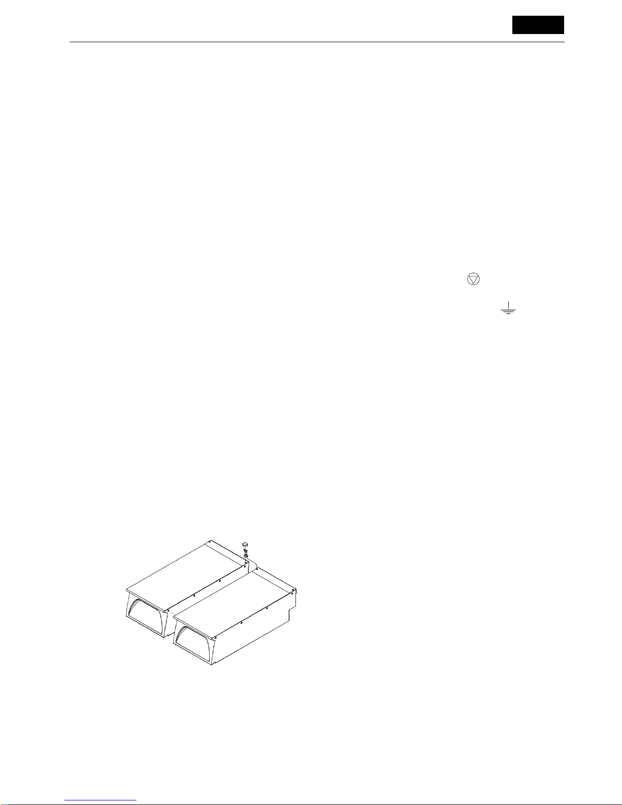
Connecting appliances (Fig 1)
Place the appliances together and adjust them to
the same level using the adjustable feet.
Connect the appliances using the holes situated
on the side at the front and back of the hob.
Connecting to an electricity supply
Before connecting the appliance, check that the
mains voltage corresponds to the value shown on
the data plate.
The appliance must be powered by a separate
electric cable which is properly specified (see
Table T1)
The cable type should be at least H 07 RN-F.
Fixed wiring insulation must be protected by
insulated sleeving having a temperature rating of
at least 60 Deg C.
Connect the cable to the terminal board following
the instructions on the electrical diagrams on the
appliance.
Ensure the earth cable is longer than the other
cables, so that in the event that the cable clamp
breaks, it is the last lead to disconnect.
For a direct connection to a power supply, a
device which guarantees disconnection from the
power supply is required, with a minimum contact
separation of 3mm to ensure complete
disconnection in case of overvoltage in category
III, in compliance with installation instructions.
Earth and equipotential connection
The appliance must be connected to an
equipotential system –the terminal is situated
near the entry point of the electrical supply cable
and is marked by the symbol
The appliance must be earthed. Connect the
earth cable to the terminal near the
terminal block marked by the symbol
ADJUSTMENT FOR DIFFERENT VOLTAGES
To convert the appliance to a different type of voltage:
Changing the electrical connections
Remove the control panel.
Work on the terminal block, and then replace the
data plate on the side of the appliance with the
correct label indicating the new voltage and
electrical details.
PREPARING FOR OPERATION
Inspection of the electrical supply
Start the appliance following the operating
instructions and ensure that it is working correctly.
Operate the oven following the operating
instructions. Check the condition of control
devices and elements, trying all modes of heating
i.e.grill only, floor only etc.
In the event of a failure, the appliance is equipped
with a safety thermostat that interrupts the supply.
In the event of this operating, identify and rectify
the cause of the fault and restart the appliance by
resetting the thermostat manually by pushing the
red button situated under the thermostat.
Inspection of the rated thermal output
When the installation, conversion and adjustment
operations are complete or after maintenance,
please verify the condition of the appliance and
check the rated thermal output and supply voltage
as indicated in table T1.
Attention: If the electrical supply values are not
within the limits indicated in table T1, switch off the
appliance and contact your electrical supply
company.
Fig 1
ENG

IS535 ECN 3673 Page 4 of 9
POTENTIAL TROUBLESHOOTING AND SOLUTIONS
Even during correct use of the appliance, malfunctions and
breakdowns may occur. Common situations are listed
below, and checks an installer should make before
contacting the technical support centre are indicated.
If after checking, the problem remains, switch the appliance
off immediately and disconnect it from the power supply.
Contact the technical support centre.
Insufficient heating of cooking zone
Unsuitable pan material –use suitable pan
material.
Continuous heating of cooking zone at maximum power
Knob switch faulty –check and replace knob
switch.
Empty cooking zone starts operating
Pan detection sensor faulty –replace generator.
Small metal objects are heated
Pan detection sensor faulty –replace generator.
No heating of cooking zone
Pan base less than 12cm –use larger pan.
Generator defective –replace generator.
No reaction of appliance
Mains fuse/mains supply interrupted –check
mains connection.
Fuses blow when switching on
Short circuit in generator –replace generator.
REPLACING COMPONENTS WITH SPARES
ATTENTION: This section exclusively concerns technical
assistance personnel.
IMPORTANT: Before any service or maintenance, switch
off at the mains switch and disconnect the appliance from
the power supply.
All servicing, maintenance and component replacement
must be carried out by a qualified person.
Do not touch sealed components.
Inductors / Generator
Remove control knobs and control panel.
Disconnect the inductor. Remove the
conveyor/filter. Remove the conductor. Replace.
Potentiometer
Remove control knobs and control panel.
Disconnect the potentiometer from the generator.
Replace potentiometer and LED.
Glass ceramic induction cooking hob
In the event that the glass ceramic surface breaks,
replace it with an original part from our company.
INSTRUCTIONS FOR USE AND MAINTENANCE
ATTENTION: This appliance is intended for professional
use and therefore must be used by qualified or trained
personnel. It is essential to monitor the appliance during
use. During operation, parts may become hot –avoid
accidental contact.
Ensure plug/socket is accessible at all times.
If the appliance is fitted with castors, use caution
at all times when moving and lock castors when
appliance is in position.
Installation and conversion to different voltages must be
carried out by qualified and authorised installers. In the
event of problems or malfunction, switch off the appliance
at the mains. In the event of a damaged supply cord, it
must be replaced by the manufacturer, its service agent or
similarly qualified person.
If the ceramic surface is cracked, switch off at the mains
supply and contact service support.
For repairs, refer only to the authorised assistance centres
and use only genuine replacement parts
Before using the appliance, read this manual and keep it for
future reference.
The induction generator has an internal system for cooling
down. Please make sure air input and output vents are not
obstructed.
Metallic objects should not be placed on the hob surface as
they will quickly become hot.
Operators with a pacemaker or metal prosthesis should
consult their doctor before using this appliance.
Operation
Note
Only use induction suitable pots and pans with a flat bottom
and with a minimum diameter of at least 12cm for the
cooking area. The pan bottom should be clean, smooth
and dry to avoid the ceramic cooking hob being scratched.
Do not place aluminium foil or plastic containers on the
ceramic cooking hob whilst it is hot, and do not use the hob
as a storage surface. The pan should be placed centrally
over the target ring of the ceramic glass.
Glass ceramic induction cooking hob
The glass ceramic cooking hob is provided with control
knobs and indicator display integrated into the printed
surface:
Potentiometer knob to set cooking temperature.
Green neon to indicate power to the appliance.
The potentiometer knob displays the following:
Back hob
Front hob
Off
Power level
Maximum
Switching on the glass ceramic cooking hob
Turn the knob to the position indicating the desired
cooking temperature –the green neon illuminates.
Select the temperature by turning the
potentiometer knob –the lowest level corresponds
ENG

IS535 ECN 3673 Page 5 of 9
to the thinnest part of the ‘power level’ and the
highest level to the widest part.
Indicator Display Table
Power level setting
There are continuously variable power level settings
available via the rotary control knob.
Residual heat display
When a pan is removed from the hobtop and the
temperature of the ceramic glass exceeds 60C, the ‘H’
symbol is displayed indicating a hot surface. Whilst the ‘H’
display is showing, leave the induction hob connected to
the power supply. This will allow the internal cooling fans to
operate. When the ‘H’ symbol is extinguished, the mains
power supply may be switched off.
Error Codes
There are numerous error codes that identify issues within
the induction system and are primarily of use when
reporting a fault to the Service Department at Lincat. Some
errors can be cleared by turning the control to the ‘Off’
position, or completely turning off and disconnecting the
appliance before switching on again.
Pan detection function
Each zone has pan detection; this prevents the coil from
turning on without a pan present. The coil also turns off as
soon as the pan is removed.
Performance issues
A reduction in performance during cooking may be
attributed to any of the following:- a blocked air filter, a
confined location with insufficient cooling air flow or a failed
fan. These circumstances will cause the generator to
overheat. Eventually the control electronics will then shut
down the generator. (See cleaning air filter –Care and
Maintenance).
Switching off the glass ceramic induction cooking hob
Turn the knob to the ‘Off’ position and isolate the
appliance at the mains.
CARE AND MAINTENANCE
Do not use a water jet or steam cleaner, and do
not immerse this appliance.
Always disconnect the appliance from the power
supply before cleaning or maintenance.
Steel parts can be cleaned using a cloth with
water and mild detergent –aggressive or abrasive
cleaning substances such as steel wool or chlorine
based products must be avoided.
Do not use sharp objects during cleaning.
If the appliance is not to be used for a lengthy
period, disconnect from the mains supply and
clean well.
Cleaning the glass ceramic induction cooking hob
Do not use abrasive materials or detergents.
Do not use aggressive products such as oven
sprays.
Liquefied plastic materials or sugar must be
removed immediately with a suitable scraper
before the hob cools down.
When at an acceptable temperature, use a
scraper to remove debris from the glass ceramic
cooking hob.
Next clean the glass with a suitable product and
paper towels. Wipe with a damp cloth and dry.
Cleaning/Replacement of air filter
Removing and cleaning the air filter will ensure an
adequate supply of cool air and will restore
performance.
Disconnect the appliance from the power supply
after allowing to cool.
Access the air filter by tipping the appliance up at
the front –the air filter is installed beneath a pull
down latched flap in the base.
Remove the filter and clean –the filter may be put
in a dishwasher.
Replace clean filter and re-engage the latch.
Reconnect to the power supply.
Warning
Do not operate the appliance without a filter otherwise
dirt and grease will be drawn into the electronics,
impairing performance and safety.
SPARE PARTS LIST
Glass ceramic hob CG107(Q2) CG108(Q4)
Inductors IM08
Generator IM09(Q2) IM07(Q4)
Control knob 761-005-00
6 pole terminal block X59000
Rotary control (with LED) IM12
Air filter FI36
EU DIRECTIVE 2002/96/EC (WEEE)
This information note is intended exclusively for
appliances marked with the symbol
shown on the data plate applied onto
the actual product (registration label).
This symbol indicates that the appliance is
classified according to current legislation as an
electrical or electronic device. In compliance with
EU Directive 2002/96/EC (WEEE), this appliance
at the end of its service life must not be treated as
normal household waste but handed in free of
charge to available differentiated collection system
for electrical or electronic devices. The user is
responsible for delivering the used product to any
provided collection systems and is otherwise
subject to penalties in accordance with current
legislation on waste products. By using a suitable
collection system for the reuse, treatment and
waste management for environmental protection,
you are promoting recycling of the materials in this
appliance and contributing to protecting the
environment and health.
For more information concerning the available
differentiated collection systems, please consult
the local authorities or the supplier from which this
ENG
Power level setting 1-100
Residual heat display
Error codes - generator
Pan detection (no pan present)

IS535 ECN 3673 Page 6 of 9
appliance was purchased.
The manufacturers and importers comply with their
responsibility for recycling, treatment and waste
management for environmental protection both
directly and by participating in differentiated
collection systems.
SERVICE INFORMATION
For help with the installation, maintenance and
use of your Q90 equipment, please contact our
service department:
UK: 01522 875520
For non-UK customers, please contact your local
Q90 dealer
All service work, other than routine cleaning
should be carried out by one of our authorised
service agents. We cannot accept responsibility
for work carried out by other persons.
To ensure your service enquiry is handled as
efficiently as possible, please tell us:
Brief details of the problem
Product code
Type number
Serial number
All available on serial plate
Q90 reserve the right to carry out any work under
warranty, given reasonable access to the
appliance, during normal working hours, Monday
to Friday, 08:30 to 17:00.
GUARANTEE
This unit carries a comprehensive UK mainland 2
year warranty. The guarantee is in addition to, and
does not diminish your statutory or legal rights.
The guarantee does not cover:
Accidental damage, misuse or use not in
accordance with the manufacturer’s instructions
Consumable items
Damage due to incorrect installation, modification,
unauthorised service work or damage due to
scale, food debris build-up, etc.
The manufacturer disclaims any liability for
incidental, or consequential damages.
Attendance is based on reasonable access to the
appliance to allow the authorised technician to
carry out the warranty work.
Service calls to equipment under warranty will be
carried out in accordance with the conditions of
sale. Unless otherwise specified, a maximum of 15
minutes of administrative time, not spent directly
carrying out servicing work, is provided for within
the warranty. Any requirement for staff attending
the call to spend greater time than 15 minutes due
to administrative requirements, such as on health
and safety risk assessments, will be chargeable at
the prevailing rate.
ENG

IS535 ECN 3673 Page 7 of 9
SEE PEDESTAL BROCHURE FOR
PEDESTAL DIMENSIONS
APPENDIX DIMENSIONS
Q2PCVI
Q4PCV1
Q4PCVI

IS535 ECN 3673 Page 8 of 9
T1
Model
Q2PCVI
Q4PCVI
No. Cooking zones
2
4
Power per zone (kW)
5
Total connected load (Kw)
3~+E 400V 50/60 Hz
10
20
Current Per Phase (A)
15.3
30.7
Connection terminals Max (mm2)
6
6
Minimum pan diameter (mm)
120
Nominal coil diameter (mm)
270
Relative humidity
10-90% non-condensing
Ambient (operating)
0 - +40C
Supply frequency (Hz)
50 or 60
Operating frequency (kHz)
18-22
APPENDIX TECHNICAL DATA

IS535 ECN 3673 Page 9 of 9
AVVERTENZA
LA CASA COSTRUTTRICE DECLINA OGNI
RESPONSABILITÀ PER LE POSSIBILI INESATTEZZE
CONTENUTE NEL PRESENTE OPUSCOLO IMPUTABILI AD
ERRORI DI TRASCRIZIONE
O
STAMPA.
SI
RISERVA INOLTRE
IL
DIRITTO DI APPORTARE
AL PRODOTTO QUELLE MODIFICHE CHE RITIENE UTILI O
NECESSARIE, SENZA PREGIUDICARNE LE
CARATTERISTICHE ESSENZIALI.
LA DITTA COSTRUTTRICE DECLINA OGNI
E
QUALSIASI
RESPONSABILITÀ QUALORA NON VENISSERO
STRETTAMENTE OSSERVATE LE NORME CONTENUTE IN
QUESTO MANUALE.
AVERTISSEMENT
LA SOCIETE CONSTRUCTRICE DECLINE TOUTE RESPONSABILITE EN
CE QUI CONCERNE LES EVENTUELLES INEXACTITUDES
CONTENUES DANS CET OPUSCULE, IMPUTABLES
A
DES ERREURS
DE TRANSCRIPTION OU D'IMPRIMERIE.
ELLE SE RESERVE LE DROIT D'APPORTER
A
SES PRODUITS LES
MODIFICATIONS QU'ELLE RETIENDRA UTILES
OU NECESSAIRES, SANS TOUTEFOIS EN COMPROMETTRE LES
CARACTERISTIQUES ESSENTIELLES.
LA SOCIETE CONSTRUCTRICE DECLINE TOUTE RESPONSABILITE
EN CAS DE NON RESPECT DES NORMES CONTENUES DANS CET
OPUSCULE.
WARNING
THE MANUFACTURER CANNOT BE HELD RESPONSIBLE
FOR ANY INACCURACIES IN THIS BOOKLET DUE
TO ERRORS IN COPYING OR PRINTING.
DUE TO ITS POLICY OF CONTINUAL PRODUCT IMPROVEMENT,
THE MANUFACTURER RESERVES THE RIGHT
TO MAKE ANY CHANGES DEEMED NECESSARY.
THE MANUFACTURER CANNOT BE HELD RESPONSIBLE
IF
THE INSTRUCTIONS CONTAINED IN THIS MANUAL ARE NOT
OBSERVED.
ADVERTENCIA
LA CASA CONSTRUCTORA DECLINA CUALQUIER
RESPONSABILIDAD
DEBIDA
A
LAS IMPRECISIONES CONTENIDAS
EN EL PRESENTE FOLLETO ATRIBUIDAS
A
ERRORES DE
TRANSCRIPCIÓN
O
IMPRENTA.
ADEMÁS SE RESERVA EL DERECHO DE APORTAR AL PRODUC- TO
LOS CAMBIOS QUE CONSIDERE ÚTILES
Y
NECESARIOS, SIN
COMPROMETER LAS CARACTERÍSTICAS ESENCIALES.
LA EMPRESA CONSTRUCTORA DECLINA CUALQUIER
RESPONSABILIDAD EN CASO DE QUE NO SE RESPETEN
LAS NORMAS CONTENIDAS EN ESTE MANUAL.
WARNUNG
DIE HERSTELLERFIRMA LEHNT JEGLICHE
UNGENAUIGKEITEN IN DER VORLIEGENDEN
BROSCHÜRE DURCH ÜBERTRAGUNGS- ODER
DRUCKFEHLER AB.
SIE BEHÄLT SICH AUSSERDEM DAS RECHT VOR, AM
PRODUKT ÄNDERUNGEN VORZUNEHMEN, DIE SIE FÜR
PASSEND ODER NOTWENDIG HÄLT, OHNE DADURCH SEINE
WESENTLICHEN EIGENSCHAFTEN ZU VERÄNDERN. DIE
HERSTELLERFIRMA LEHNT JEGLICHE VERANTWORTUNG AB,
WENN DIE IN DIESER BETRIEBSANWEISUNG ENTHALTENEN
VORSCHRIFTEN NICHT STRENGSTENS EINGEHALTEN
WERDEN.
WAARSCHUWING
DE FIRMA WIJST IEDERE VERANTWOORDELIJKHEID AF
VOOR MOGELIJKE NIET-JUISTE INFORMATIE DIE IN DIT
HANDBOEK STAAT EN DIE ONTSTAAN
IS
DOOR FOUTEN
DIE GEMAAKT ZIJN BIJ HET OVERSCHRIJVEN OF DRUKKEN. DE
CONSTRUCTEUR BEHOUDT ZICH HET RECHT VOOR
OM DIE WIJZIGINGEN IN HET PRODUCT AAN TE BRENGEN, DIE
HIJ NUTTIG OF NOODZAKELIJK ACHT, ZONDER
DE ESSENTIELE EIGENSCHAPPEN AAN TE TASTEN.
DE CONSTRUC TEUR WIJST IEDERE VERANTWOORDELIJKHEID AF
IN HET GEVAL DE NORMEN, DIE IN DEZE
HANDLEIDING STAAN, NIET STRIKT OPGEVOLGD WORDEN.
Whisby Road, Lincoln, LN6 3QZ, United Kingdom
Sales Tel: 0044 (0)1522 875500
Service Tel: 0044 (0)1522 875520
General Tel: 0044 (0)1522 875555
e-mail: [email protected]
This manual suits for next models
1
Table of contents
Popular Cooktop manuals by other brands

Blue Star
Blue Star RBCT365BSS Installation and user instructions

Elite
Elite SQ6VR 04 Use, installation and maintenance instructions

Falcon
Falcon 1092 Deluxe Induction G5 User's guide & installation instructions

KitchenAid
KitchenAid KECC051H Use and care guide

Kramer
Kramer TP-300FW user manual

Frigidaire
Frigidaire GLEC30S8A Factory parts catalog