manuals.online logo
Brands
  1. Home
  2. •
  3. Brands
  4. •
  5. Qdecoder
  6. •
  7. Media Converter
  8. •
  9. Qdecoder Z2-8 User manual

Qdecoder Z2-8 User manual

Quick start guide
Using the Programming Button
These instructions are valid for the Qdecoder Z2-8
Ex works a Z2 decoder is confi gured for two aspect signals (red/green)
with the (DCC) accessory addresses 1 through 8.
The decoder automatically switches over to Märklin/Motorola, if it
detects a Märklin/Motorola programming command or if CV57 is set to
value “2”.
Using the programming button you can confi gure all function outputs of a
Qdecoder to the same mode and determine their accessory addresses
with a single command from your command station.
You may confi gure the following operating modes of a Z2 with the
programming button:
command mode pulse duration
1 2)
turnout
and motors
without soft start
¼ s
1 ½ s
2 1 s
2 2 s
3
continuous operation
3 ... with soft start
4
4 lighting decoder
2) The number is the accessory address to be entered on the command station.
Press the buttons respectively as programming commands.
In soft start mode the revs of the motor will be accelerated respectively
decelerated within a quarter second. In this mode one can also control
two-aspect block signals (red/green). The signal lamps of a block signal are
wired to the terminals and of a output group A0/A1 through A6/A7 of
the decoder. The common return wire of the signal must be wired to one of
the blue terminals .
The duration of the run up can be changed in the confi guration variables
CV114 for A0, CV124 for A1, CV134 for A2 and so forth. The switch-off time
is determined by the setting of CV115 for A0, CV125 for A1, CV135 for A2
and so forth.
Lighting Mode
(
programming command 4
)
Each of the outputs A0 through A7
are controlled individually under
separate accessory addresses.
The outputs are confi gured for
continuous mode and are faded in
respectively out within a quarter
second.
command for switching
L1 L2 L3 L4 L5 L6 L7 L8 L9 L10 L11 L12 L13 L14 L15 L16
41 2 3 4 5 6 7 8 1 2 3 4 5 6 7 8
8 5 6 7 8 9 10 11 12 5 6 7 8 9 10 11 12
+4 +4 /
When switching on L9, then L1 is turned off and vice versa.
You can change the addresses of the pairs of lamps under the following CVs:
accessory addresses
lamps L1 and L9 AL1,L9 = CV1 + 256 · CV9
lamps L2 and L10 AL2,L10 = CV552 + 256 · CV551
lamps L3 and L11 AL3,L11 = CV555 + 256 · CV554
lamps L4 and L12 AL4,L12 = CV558 + 256 · CV557
lamps L5 and L13 AL5,L13 = CV561 + 256 · CV560
lamps L6 and L14 AL6,L14 = CV564 + 256 · CV563
lamps L7 and L15 AL7,L15 = CV567 + 256 · CV566
lamps L8 and L16 AL8,L16 = CV570 + 256 · CV569
Prog
Z2
decoder
© Copyright Qelectronics GmbH 03/2014
A0 A1 A2 A3 A4 A5 A6 A7
L9L1 L10L2 L11L3 L12L4 L13L5 L14L6 L15L7 L16L8
1
4
Confi guration Step-by-step
1. Select the suitable operating mode from the table.
2. Select the accessory address you wish to assign to the fi rst accessory.
3. Determine the required programming command.
In order to set other accessory addresses than 1 through 4, you have to
add an offset to the address. This offset is determined as follows:
▪ Example 1:
Take the programming command “3 ” from the table.
The decoder shall be programmed to the addresses 201 through 204.
- Deduct 1 from desired address: 201 - 1 = 200
- Add the address of the programming command: 200 + 3 = 203
- Required command: “203 ”
▪ Example 2:
Programming command as per the manual: “4 ”.
The decoder shall be programmed to the addresses 17 through 24.
17 - 1 + 4 = 20  Programming command “20 ”
4. Press the programming button Prog of the decoder and hold it down
for about one second, until the LED lights up continuously. Now release
the button again. The LED remains lit indicating that the decoder has
switched over from normal operating mode into programming mode.
Terminate the programming mode by pressing the button briefl y.
5. Send the determined programming command with your command station.
6. Successful programming is indicated by the extinguishing LED. The
decoder changes over into the newly set operating mode.
Now you can change the operating mode, the addresses as well as the
other properties of the function outputs (e.g. dimming or blinking) for
each connected device by CV programming.
 Turnouts and Semaphore Signals
(
programming command 1
,
1
,
2
,
2
,
3
)
Motors with Soft Start
(
programming command 4
)
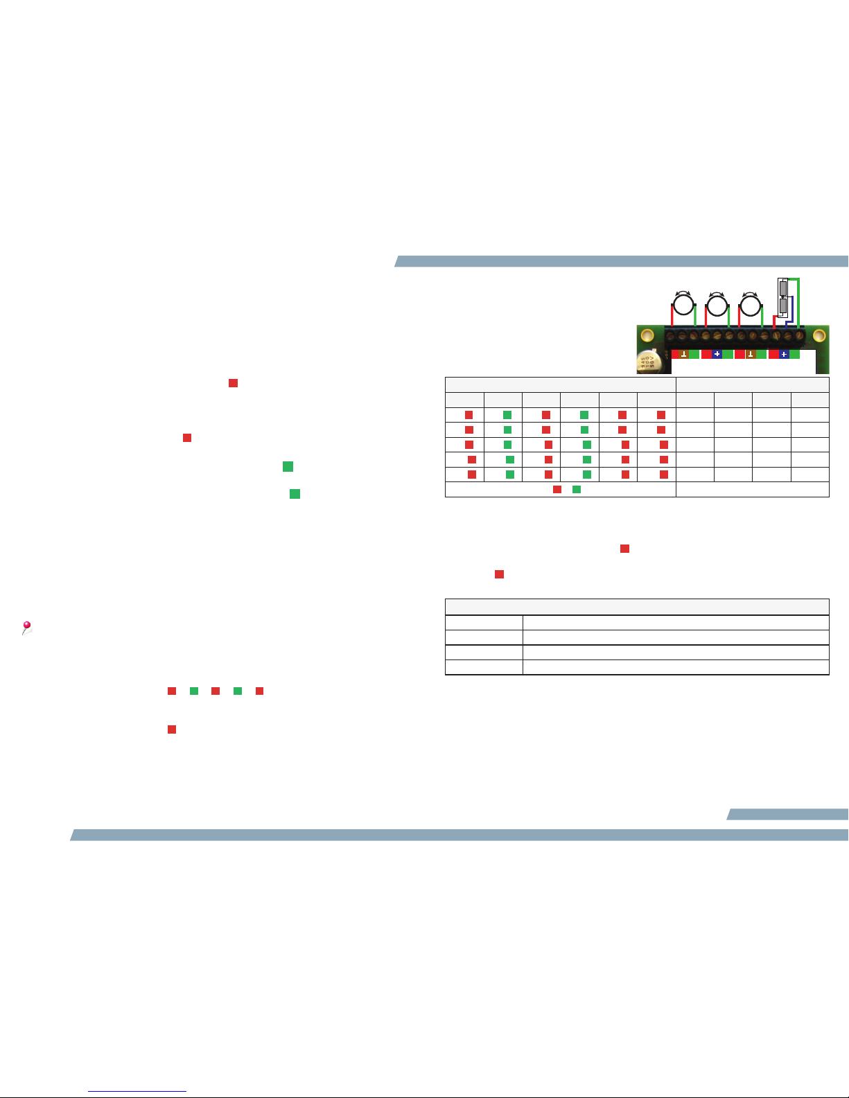
You may connect motorised (in the picture on the left) or magnetic drives
in combination to the decoder. The motor leads are only shown in principle.
For turnout drives of certain manufacturers the specifi c wiring is compiled
in the leafl et “Electrical connections“.
The operating mode “Turnouts in continuous mode” is suitable for turnout
drives with limit contacts. Other types of turnouts must be controlled in
pulse mode. In most cases the
shortest pulse duration is adequate.
Should the turnout not work reliably,
simply set a longer pulse duration.
After programming each turnout can
be controlled with a push button
under the following accessory
address:
progr. command for pulse duration of addrresses for switching
¼ s ½ s 1 s 2 s 1) 2) T1 T2 T3 T4
1 1 2 2 3 4 12 3 4
5 5 6 6 7 8 5678
9 9 10 10 11 12 910 11 12
13 13 14 14 11 16 13 14 15 16
17 17 18 18 19 20 17 18 19 20
+4 / +4
1) Continuous mode with immediate switch-on
2) Continuous mode with soft start
Examples:
• The programming command “19 ”sets the decoder to continuous mode with
the addresses 17 through 24.
• “246 ”: Pulse mode (1 second pulse duration), addresses 245 through 252.
You may change the turnout addresses in following CVs:
accessory addresses
turnout 1 AW1 = CV1 + 256 * CV9
turnout 2 AW2 = CV555 + 256 * CV554
turnout 3 AW3 = CV561 + 256 * CV560
turnout 4 AW4 = CV567 + 256 * CV566
Example: Write the value 700 /256 = 2 in CV567 and the value 700 - (2 * 256) = 188 in
CV566 in order to program turnout 4 to address 700.
If so desired change the duration of the switch pulse with the programming
command then simultaneously set the time with the CVs 3 through 6 for two
function outputs each from A0 through A7 to a maximum of 2.55 seconds.
In CV117/CV116 you can change the switching time for A0 independent of
the time set for A1 (CV127/CV126), (CV137/CV136 for A2, and so forth up
to CV277/CV276 for A15). The maximum possible time here is just under
11 minutes.
Wei/Sig 1
A0 A1
Wei/Sig 2
A2 A3
Wei/Sig 3
A4 A5
Wei/Sig 4
A6 A7
2011
Z1-16
turnout W1 turnout W2 turnout W
3
turnout W4
MM M
2 3

Other Qdecoder Media Converter manuals

Qdecoder Z2-8 Series User manual

Qdecoder

Qdecoder Z2-8 Series User manual

Qdecoder Z1 Series User manual

Qdecoder

Qdecoder Z1 Series User manual

Qdecoder Z2-8+ User manual

Qdecoder

Qdecoder Z2-8+ User manual

Popular Media Converter manuals by other brands

Lika ES58S Series Mounting instructions

Lika

Lika ES58S Series Mounting instructions

HEIDENHAIN ERO 1225 Mounting instructions

HEIDENHAIN

HEIDENHAIN ERO 1225 Mounting instructions

tams elektronik LD-G-9 manual

tams elektronik

tams elektronik LD-G-9 manual

Digitus professional DN-95205 quick start guide

Digitus professional

Digitus professional DN-95205 quick start guide

ADS Technologies HDUP-1500 operating instructions

ADS Technologies

ADS Technologies HDUP-1500 operating instructions

Vogel SAVA 1021 quick start guide

Vogel

Vogel SAVA 1021 quick start guide

TRENDnet TFC-110MSTE user guide

TRENDnet

TRENDnet TFC-110MSTE user guide

Contemporary Controls CTRLink EIMK-100T/FT installation guide

Contemporary Controls

Contemporary Controls CTRLink EIMK-100T/FT installation guide

ExpertDAQ EX9133C Series Operation manual

ExpertDAQ

ExpertDAQ EX9133C Series Operation manual

Reliance 13-030 installation instructions

Reliance

Reliance 13-030 installation instructions

Microsens MS400240 user manual

Microsens

Microsens MS400240 user manual

Optics MVDF user manual

Optics

Optics MVDF user manual

gefran EXP-MBTCP-ADV manual

gefran

gefran EXP-MBTCP-ADV manual

PMA Mobile 0430 manual

PMA Mobile

PMA Mobile 0430 manual

moon MOON 750 D owner's manual

moon

moon MOON 750 D owner's manual

Klein Tools 69409 quick start guide

Klein Tools

Klein Tools 69409 quick start guide

C&C TECHNIC Smart View VSS-814PF user manual

C&C TECHNIC

C&C TECHNIC Smart View VSS-814PF user manual

Keysight 34951A user guide

Keysight

Keysight 34951A user guide

manuals.online logo
manuals.online logoBrands
  • About & Mission
  • Contact us
  • Privacy Policy
  • Terms and Conditions

Copyright 2025 Manuals.Online. All Rights Reserved.