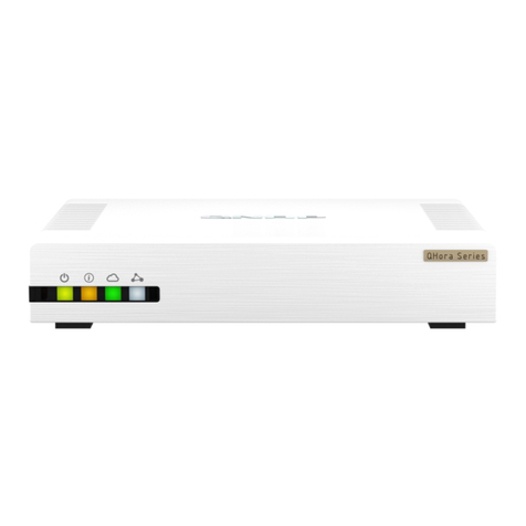
QNAP iVW-FH233 User manual

2014/10/05
iVW-FH233 Video Wall Controller
User Manual
Version 1.01

iVW-FH233 User Manual
2
Table of Contents
Table of Contents ............................................................................................... 2
Legal Noti e and Dis laimer ............................................................................... 5
EGA NOTICE ...................................................................................................... 5
DISC AIMER......................................................................................................... 5
REGU ATORY NOTICE .............................................................................................. 7
SAFETY WARNINGS .............................................................................................. 10
1. Introdu tion ................................................................................................. 11
1.1 INTRODUCTION ............................................................................................. 11
1.2 BENEFITS ................................................................................................... 11
1.3 FEATURES ................................................................................................... 11
2. Hardware Spe ifi ations ............................................................................... 13
2.1 FRONT PANE ............................................................................................... 13
2.2 REAR PANE ................................................................................................ 13
2.3 TECHNICA SPECIFICATIONS ............................................................................. 14
2.4 DIMENSIONS ............................................................................................... 15
2.5 POWER SWITCH AND RESET BEHAVIOR ................................................................. 15
2.6 ED SPECIFICATIONS ..................................................................................... 16
3. Getting Started ............................................................................................. 17
3.1 INSTA ATION STEPS ...................................................................................... 17
3.2 INSTA DISP AY DEVICES ............................................................................... 17
3.3 MOUNTING .................................................................................................. 17
3.4 CONNECT CAB ES ......................................................................................... 18
3.4.1 Connect the Video Source and iVW-FH233 .............................................. 18
3.4.2 Connect iVW-FH233 and the Display Devices .......................................... 18
3.4.3 Connect the ower Adapter to iVW-FH233 .............................................. 19
4. Input and Output Resolution ........................................................................ 20
4.1 ASPECT RATIO ............................................................................................. 20
4.2 INPUT RESO UTION ........................................................................................ 20
4.3 OUTPUT RESO UTION ..................................................................................... 20
5. Display Mode ................................................................................................ 21

iVW-FH233 User Manual
3
5.1 3 X 3 DISP AY MODE ..................................................................................... 21
5.2 2 X 2 DISP AY MODE ..................................................................................... 22
5.3 1 X 1 DISP AY MODE ..................................................................................... 22
5.4 3 X 2 DISP AY MODE ..................................................................................... 23
5.5 2 X 3 DISP AY MODE ..................................................................................... 24
6. OSD Menu Fun tions .................................................................................... 25
6.1 OSD BUTTONS ............................................................................................. 25
6.2 OSD MENU STRUCTURE .................................................................................. 25
6.3 OUTPUT RESO UTION MENU ............................................................................. 26
6.4 DISP AY MODE MENU ..................................................................................... 26
6.5 BEZE COMPENSATION MENU ............................................................................ 27
6.6 SYSTEM OPTION MENU ................................................................................... 28
6.7 SYSTEM INFORMATION MENU ............................................................................ 30
6.8 REMOTE CONTRO ......................................................................................... 30
7. Te hni al Support......................................................................................... 32
List of Figures
Figure 1-1: iVW-FH233 .......................................................................... 11
Figure 2-1: iVW-FH233 Front Panel
....................................................... 13
Figure 2-2: iVW-FH233 Rear Panel ........................................................ 14
Figure 2-3: iVW-FH233 Dimensions....................................................... 15
Figure 3-1: Cable Conne tion ................................................................ 18
Figure 5-1: Display Mode ...................................................................... 21
Figure 5-2: 3 x 3 Display Mode Setup .................................................... 22
Figure 5-3: 2 x 2 Display Mode Setup .................................................... 22
Figure 5-4: 1 x 1 Display Mode Setup .................................................... 23
Figure 5-5: 3 x 2 Display Mode Setup .................................................... 23
Figure 5-6: 2 x 3 Display Mode Setup .................................................... 24
Figure 6-1: OSD Buttons ....................................................................... 25
Figure 6-2: Output Resolution Menu ..................................................... 26
Figure 6-3: Display Mode Menu ............................................................. 27
Figure 6-4: Bezel Compensation Menu .................................................. 28
Figure 6-5: System Option Menu
........................................................... 29
Figure 6-6: OSD Position Window ......................................................... 29
Figure 6-7: System Information Menu
................................................... 30

iVW-FH233 User Manual
4
Figure 6-8: Remote Controller ............................................................... 31
List of Tables
Table 2-1: Te hni al Spe ifi ations ....................................................... 14
Table 2-2: Power Swit h Behavior ........................................................ 15
Table 2-3: LED Indi ators Behavior ....................................................... 16
Table 6-1: OSD Menu Stru ture
............................................................. 26

iVW-FH233 User Manual
5
Legal Noti e and Dis laimer
This user manual provides a description of the iVW Video Wall Controller’s hardware
and relevant guidelines for key functions. Please read this document carefully and
adhere to its instructions.
This manual provides the description of all the functions of the iVW Video Wall Controller.
The product you purchased may not support certain functions dedicated to specific
models.
Legal Noti e
•All features, functionality, and other product specifications are subject to change
without prior notice or obligation.
•Information presented is subject to change without notice.

iVW-FH233 User Manual
6
Note:
1.
Back up your system periodically to avoid any potential data loss.
2. Should you return any components of the iVW-FH233 package for refund or
maintenance, make sure they are carefully packed for shipping. Any form of damage
caused by improper packaging will not be compensated.

iVW-FH233 User Manual
7
Regulatory Noti e
FCC Noti e
FCC Class A Noti e
This device complies with Part 15 of the FCC Rules. Operation is subject to the following
two conditions:
1. This device may not cause harmful interference.
2. This device must accept any interference received, including interference that may
cause undesired operation.
Note: This equipment has been tested and found to comply with the limits for a Class A
digital device, pursuant to Part 15 of the FCC Rules. These limits are designed to provide
reasonable protection against harmful interference when the equipment is operated in a
commercial environment. This equipment generates, uses, and can radiate radio
frequency energy, and if not installed and used in accordance with the instruction manual,
may cause harmful interference to radio communications. Operation of this equipment in
a residential area is likely to cause harmful interference, in which case the user will be
required to correct the interference at their own expense.

iVW-FH233 User Manual
8

iVW-FH233 User Manual
9
Symbols in this do ument
Warning
This icon indicates instructions that must be strictly followed.
Failure to do so may result in injury or death.
Caution
This icon indicates the action may lead to disk clearance/loss OR
failure to follow the instructions could result in data damage, disk
damage, or product damage.

iVW-FH233 User Manual
10
Safety Warnings
1. The iVW video wall controller can operate normally in a temperature between
0ºC–40ºC and in a relative humidity of 0%–95%. Please ensure the operating
environment is well-ventilated.
2. The power cord and devices connected to the iVW video wall controller must provide
a correct supply voltage (100W, 90–264V).
3. Do not place the iVW video wall controller in direct sunlight or near chemicals.
4. Unplug the power cord and all connected cables before cleaning. To clean the iVW
video wall controller, wipe it with a dry towel. Do not use chemicals or aerosols to
clean the iVW video wall controller.
5. Do not cover or place any objects on the iVW video wall controller to ensure normal
operation and to avoid overheating.
6. Use the flat head screws in the product package to lock the hard disks in the iVW
video wall controller when installing hard disks.
7. Do not place the iVW video wall controller near any liquid.
8. Do not place the iVW video wall controller on an uneven surface to avoid it falling..
9. Make sure the voltage is correct in the location where the iVW video wall controller is
installed. Contact the distributor or the local power supply company for more
information.
10. Do not place any object on the power cord.
11. Under no circumstances should you attempt to repair the iVW video wall controller.
Improper disassembly of the product may expose the users to electric shock and
other risks. For any enquiries regarding repairing the iVW video wall controller, please
contact the distributor.
12. iVW video wall controllers should only be installed in server rooms and maintained by
authorized server managers or IT administrators. The server room should be secured
and only accessible by authorized staff members.
Warning:
There is the possibility of an explosion if the battery is replaced incorrectly. Replace only
with the same or equivalent type recommended by the manufacturer. Dispose of used
batteries according to the manufacturer’s instructions.
DO NOT touch the system fan as it may cause injury and hardware failure.

1. Introdu tion
1.1 Introdu tion
Figure 1-1: iVW-FH233
The iVW-FH233
video wall controller box is for displaying a single video input on an array
of monitors, implementing a large display without the inherent high costs of a single large
monitor. The iVW-FH233
is for large displays where high definition video output is
essential. The video wall
controller accepts a single HDMI
the monitors in the array.
1.2 Benefits
The benefits of the iVW-
FH233
•Accurate, high-
definition
•Silent operation
•HDCP support
•Simple setup
•Cost-saving
implementation of a large display
•
Major power saving
•Space saving
1.3 Features
The features of the iVW-
FH233
•One HDMI input
•Nine HDMI outputs
•Supports
up to 1920 x 1080 output resolution per monitor
•Supports
multiple display modes, including clone mode (1 x 1) and full mode (2 x
iVW-
FH233 User Manual
11
video wall controller box is for displaying a single video input on an array
of monitors, implementing a large display without the inherent high costs of a single large
is for large displays where high definition video output is
controller accepts a single HDMI
input, which is split over all
FH233
include:
definition
image quality
implementation of a large display
Major power saving
compared to PC-based implementation
FH233
include:
up to 1920 x 1080 output resolution per monitor
multiple display modes, including clone mode (1 x 1) and full mode (2 x
FH233 User Manual
video wall controller box is for displaying a single video input on an array
of monitors, implementing a large display without the inherent high costs of a single large
is for large displays where high definition video output is
input, which is split over all
of
multiple display modes, including clone mode (1 x 1) and full mode (2 x

iVW-FH233 User Manual
12
2, 2 x 3, 3 x 2, 3 x 3)
•HDCP support for compliance with Blu-ray Disc players and video game consoles
•Genimask bezel compensation technology for compensating for gaps between
monitors
•RS232 for firmware upgrade and system integration
•3.5mm audio out to support analog sound systems
•Fanless design for easy maintenance and silent operation

2. Hardware
Spe
Caution:
Modifying the hardware, software, or firmware of
roducts.
possible data loss and
system instabilities
default
system firmware or installing unau
products.
2.1 Front Panel
The f
ront panel has the following buttons and indicators:
•One power ED
indicator
•
One video input ED
•
Nine video output ED
•Six OSD buttons
•
One Infrared sensor
Figure 2-1: iVW-FH233
Front Panel
2.2 Rear Panel
The rear panel has the following connectors and switches:
•One HDMI input
•Nine HDMI outputs
•One power input
•One RS232
•One power switch
iVW-
FH233 User Manual
13
Spe
ifi ations
Modifying the hardware, software, or firmware of
the
QN
will void the warranty. We
or
caused by modding our products.
Users
will be solely responsible for the risks
system instabilities
caused by modifying
hardware,
system firmware or installing unau
thorized third-
party applications on
ront panel has the following buttons and indicators:
indicator
One video input ED
indicator
Nine video output ED
indicators
One Infrared sensor
Front Panel
The rear panel has the following connectors and switches:
FH233 User Manual
the
products
is not responsible for any form of dama
are not responsible for any form of damaggee or
loss of data
will be solely responsible for the risks
of
hardware,
altering the
party applications on
our

Figure 2-2: iVW-FH233
Rear Panel
2.3
Te hni al Spe ifi ations
Spe ifi ation
Model
Main Features
Video Input
Video Output
Input Resolution
Support
Output Resolution
Support
Display Mode
Audio Output
Serial
Buttons
Power
Mounting
Dimensions (D x W x H
)
Weight
Constru tion
Operating Temperature
Certifi ation
Table 2-1: Te hni al S
pe ifi ations
iVW-
FH233 User Manual
14
Rear Panel
Te hni al Spe ifi ations
Des ription
iVW-FH233
•Multipl
e output resolution support
•Multiple display mode support
•
Genimask bezel compensation technology
•Remote controller included
1 x HDMI
9 x HDMI
640 x 480, 720 x 480 (480p),
800 x 600
1152 x 864, 1280 x 720 (720p),
1280 x 800
1280 x 1024, 1360 x 768,
1366 x 768
x 1200, 1680 x 1050, 1920 x 1080
(1080p)
1024 x 768, 1280 x 720, 1360 x 768
,
x 1080 (1080p)
1 x 1 (clone), 2 x 2, 2 x 3, 3 x 2,
3 x 3
1 x 3.5mm audio out
1 x RS232
1 x Power button
6 x OSD buttons
100~240V AC, 60W
Wall mount
)
295 x 191 x 65 mm
1.4 kg
Fanless design
0ºC to 40ºC with air flow
CE, FCC Class A, VD
pe ifi ations
FH233 User Manual
e output resolution support
Genimask bezel compensation technology
800 x 600
, 1024 x 768,
1280 x 800
, 1280 x 960
,
1366 x 768
, 1440 x 900,
1600
(1080p)
,
1366 x 768,
1920
3 x 3

iVW-FH233 User Manual
15
2.4 Dimensions
•Height: 65 mm (71.4mm with rubber feet)
•Width: 295 mm
•Depth: 191 mm
Figure 2-3: iVW-FH233 Dimensions
2.5 Power Swit h and Reset Behavior
Toggle the power switch to turn on or turn off the video wall controller.
Power swit h
(Turn on)
Power swit h
(Turn off)
Toggle once Toggle once
Table 2-2: Power Swit h Behavior

iVW-FH233 User Manual
16
To reset the device, press and hold the "Up" OSD button while toggling the power switch
to start the iVW-FH233. Hold the "Up" OSD button until the power ED flashes orange
then release it. The power ED will stop flashing orange when the reset process is done.
2.6 LED Spe ifi ations
This session applies to all the models in iVW Full HD series (iVW-FHxxx).
The ED indicators of the iVW video wall controllers indicate the system’s status and other
information. When the iVW video wall controller is turned on, check the following items to
make sure the system status is normal. Note that the following ED information is
applicable only when users have properly installed the device, and connected the iVW
video wall controller to the power adapter.
LED Color LED Status Des ription
Power
Green
Green The iVW video wall controller is ready.
Off The iVW video wall controller is off.
Orange
Flashes
orange every
0.5 sec
The iVW video wall controller is in reset
process
Video
Input Green
Green The video input is ready.
Off No video input detected
Video
Output Green
Green The video output is ready
Off No video output detected
Table 2-3: LED Indi ators Behavior

iVW-FH233 User Manual
17
3. Getting Started
3.1 Installation Steps
To install the iVW-FH233, please follow the installation steps below.
1. Install the display devices.
2. Mount the iVW-FH233 (optional).
3. Connect HDMI cables for video input and output, RS232 cable (optional), and power
adapter to the iVW-FH233.
4. Adjust the output resolution. See Input and Output Resolution for more
information.
5. Select a display mode. See Display Mode for more information.
6. Adjust the iVW-FH233 bezel compensation setting to align the images (optional).
3.2 Install Display Devi es
The display devices ( CD monitors, TVs) are installed in a rectangular arrangement by
following your chosen display mode.
Recommended installation procedures are:
•Use identical display devices
•Keep the gaps between panels as small as possible
•Keep all horizontal gaps between monitors in the array consistent
•Keep all vertical gaps between monitors in the array consistent
3.3 Mounting
The iVW-FH233 must be placed on a table, desk or any other firm surface. The
iVW-FH233 can also be mounted using the included mounting brackets. The installation
location must be:
•Out of direct sunlight
•Without anything on top of it
•On a firm surface
•Away from moisture and liquids

3.4
Conne t Cables
The c
ables that need to be attached are listed below
Figure 3-1:
•HDMI input cable
–
iVW-FH233.
•HDMI
output cables
controllers. Make sure the cables are connected to the correct monitors
in Figure 3-1.
•Power cable – fr
om the power adapter
Figure 3-1: Cable C
onne tion
3.4.1
Conne t the Video Sour e and
The video source directly
connects to the
the video source to the
iVW
1. Attach the HDMI
video cable to the
2. Attach the HDMI
video cable to the
3.4.2 Conne t iVW-
FH233 and
The iVW-FH233 directly
connects to the
the iVW-FH233
to the display devices
1. Attach the HDMI
video cable
2. Attach the HDMI
video cable
iVW-
FH233 User Manual
18
Conne t Cables
ables that need to be attached are listed below
and their conne
c
–
from the video source
(PC, console, player, etc)
output cables
– from the iVW-FH233
to the CD panels or other video box
controllers. Make sure the cables are connected to the correct monitors
om the power adapter
.
onne tion
Conne t the Video Sour e and
iVW-FH233
connects to the
iVW-FH233 through
an HDMI
iVW
-FH233, follow these steps:
video cable to the
HDMI
output of the video source.
video cable to the
HDMI input on the iVW-
FH233
FH233 and
the Display Devi es
connects to the
display devices through HDMI
to the display devices
, follow these steps:
video cable
s to the HDMI output of the iVW-
FH233
video cable
s to the HDMI input on the
display devices.
FH233 User Manual
c
tions are shown in
(PC, console, player, etc)
to the
to the CD panels or other video box
controllers. Make sure the cables are connected to the correct monitors
as shown
an HDMI
cable. To connect
output of the video source.
FH233
.
cables. To connect
FH233
.
display devices.

iVW-FH233 User Manual
19
3.4.3 Conne t the Power Adapter to iVW-FH233
Connect the included power adapter to the iVW-FH233.

iVW-FH233 User Manual
20
4. Input and Output Resolution
Correct adjustment of the input and output resolutions gives a greater image quality.
Follow the steps outlined in the subsections below to get the best image quality from the
iVW video wall controller.
4.1 Aspe t Ratio
With auto-scaling it is not necessary to match the input and output aspect ratios.
However for the best visual experience the input and output aspect ratios should be
identical.
4.2 Input Resolution
The input resolution should be set as high as possible. Pick a resolution that meets the
following criteria for best visual experience:
•Matches the display device's aspect ratio
•Is the maximum possible resolution (without exceeding input resolution limits)
The iVW-FH233 supports the following input resolutions.
640 x 480, 720 x 480 (480p), 800 x 600, 1024 x 768, 1152 x 864, 1280 x 720 (720p),
1280 x 800, 1280 x 960, 1280 x 1024, 1360 x 768, 1366 x 768, 1440 x 900, 1600 x 1200,
1680 x 1050, 1920 x 1080 (1080p)
4.3 Output Resolution
The output resolution should be set as high as possible, and meet the following criteria for
the best visual experience:
•Matches video input and display device aspect ratio
•Is the maximum possible resolution
•Has a minimum width greater than half input width
•Has a minimum height greater than half input height
The iVW-FH233 supports the following output resolutions.
1024 x 768, 1280 x 720 (720p), 1360 x 768, 1366 x 768, 1920 x 1080 (1080p)
Table of contents
Other QNAP Network Router manuals
Popular Network Router manuals by other brands

Teldat
Teldat ATLAS X60 installation manual

Huawei
Huawei S6700 Series Configuration guide

Deltenna
Deltenna WiBE HS21 quick start guide

ZyXEL Communications
ZyXEL Communications P-660RU-Tx Series Support notes

Advantech
Advantech MIC-3666 user manual

Allied Telesis
Allied Telesis AT-9000/12PoE installation guide