ecember 2022 Rev 4.0 | Subject to change without notice
5 of 20
USER’S GUIDE UG145
Recommended Operating Conditions
The ACT41000EVK1-104 is designed for a 24V-40V input voltage. The maximum operating voltage is determined by the
IC’s maximum input voltage rating. The minimum operating voltage is determined by the IC’s output voltage setting. The
ACT41000-104T output voltage is 22V, so the EVK should be operated with Vin greater than 22V. The maximum output
current is configured by the CMI and external components. The switching frequency is set to 450kHz to optimize efficiency.
The customer can easily reconfigure the EVK for different switching frequencies and output voltages after referring to the
datasheet for the required component changes. The output voltage can be changed via I2C either before or after the output
voltage is enabled.
Table 1. Recommended Operating Conditions
V5V_max
Mini-buck maximum output current
out_max
Main-buck maximum output current
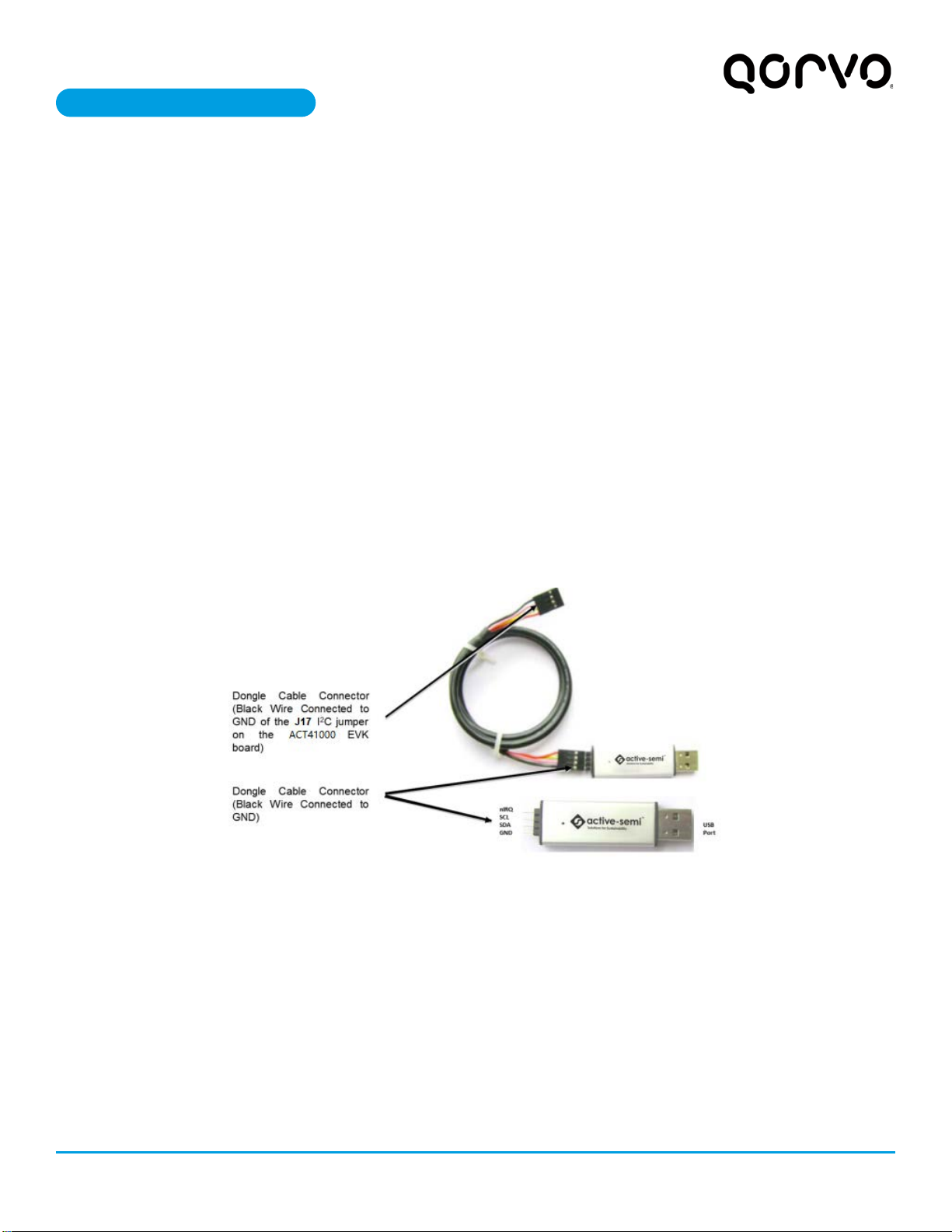
EVK Operation
Turn On the Evaluation Board
After the power source and E-Load are connected to the evaluation board per the required connections, the EVK can be
powered for operation. Perform the following steps to turn on the board.
1. Ensure that the power supply connected to VIN (J8) is >24V and <40V.
2. Turn on power supply.
3. Apply the load.
4. Remove the shorting jumper from J12 to enable output. Replace the jumper to disable the output.
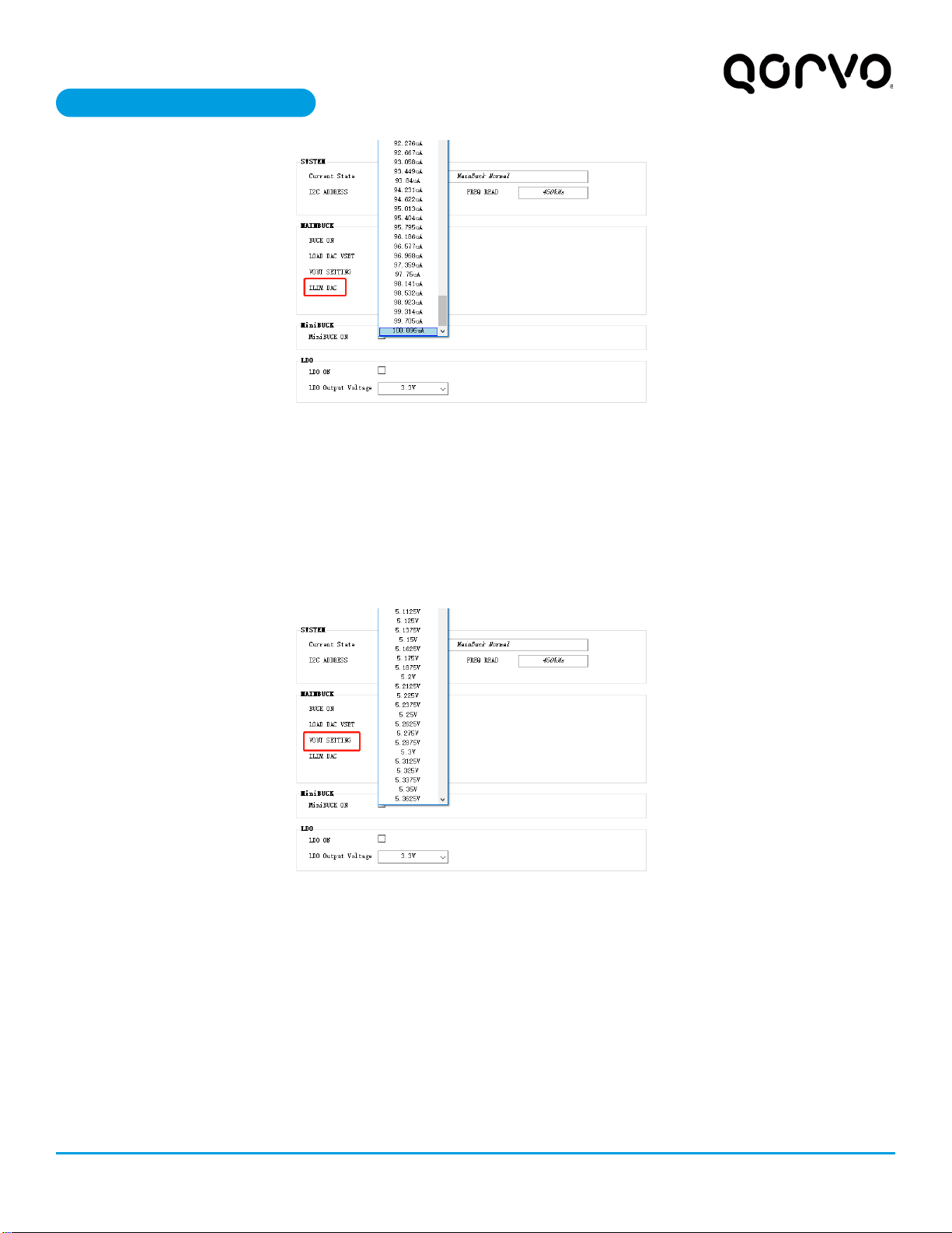
Output Current Limit – The ACT41000EVK1-104 output current limit is set to 4A. This is a function of the 20mΩ current
sense resister (R5), the 16kΩ ILIM resistor (R9), and the I2C Output Current Limit bits, which are set to 100uA by default.
The ACT41000 integrates a digital-to-analog converter (ILIM DAC) for the purpose of generating the reference signal used
by the Current Limit block. The ILIM DAC generates an output current at the ILIM pin. The output current limit is easily
changed by modifying any of these three parameters. The easiest way to change the output current limit is with the ILIM
DAC field in the GUI.