UG148
Rev. 1, 17-June-2022
Innovative PowerTM
ActiveSwitcherTM is a trademark of Qorvo.
9
Bill of Materials
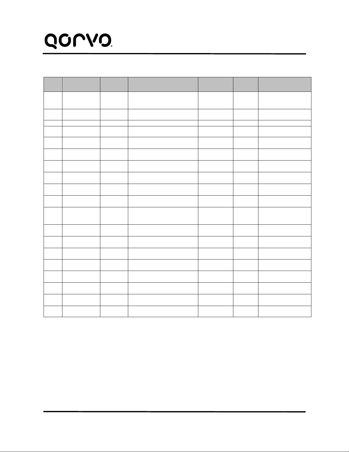
Table 2 - BOM
Item Designator Quantity Description Package Manu-
facturer PartNumber
1
C2, C3, C4, C10,
C11, C14, C15,
C16, C18, C19
12 Capacitor, Ceramic, 22uF/6.3V ’0603 Murata GRM188C80J226ME15D
2 C12,C20 0 Capacitor, Ceramic, 22uF/6.3V ’0603 Murata GRM188C80J226ME15D
3 C1,C5, C13, C17 4 Capacitor, Ceramic, 10uF/6.3V ’0402 Standard Standard
4 C6, C7, C8, C9 4 Capacitor, Ceramic, 2.2uF/6.3V ’0402 Standard Standard
5 J1, J3, J6, J9, J12 5 CON, Screw Terminal, 3.50, 2P con,tbk,350-
2p,kf350 Wurth 691214110002S
6 J7, J10, J11, J13,
J19, J20 6 CON, Header, 2.54, Male, 2P, TH con,hdr,254-2p Wurth 61300211121
7 J2, J4, J14, J15,
J16, J17, J18 7 CON, Header, 2.54, Male, 3P, TH con,hdr,254-3p Wurth 61300311121
8 J8 1 CON, Header, 2.54, Male, 4P, TH con,hdr,254-4p Wurth 61300411121
9 J5 1 CON, Header, 1.27, Male, 6P, TH con,hdr,1.27-
6P Digekey GRPB061VWVN-RC
10 D1 1 Diode, Led, Blue WL-
SMCW_0603 std Standard
11 L1, L3 2 Inductor, 0.47uH
L4020_MAPI_R
- cover-pk-
L2520
Wurth 744383560047HT
12 L2, L4 2 Inductor, 0.47uH L25xx_MAPI_R
- cover L2010 Wurth 744383240047
13 R3, R4, R5, R6,
R7, R8, R9, R10 8 Resistor, SMD,100k R0603_M Standard Standard
14 R11 1 Resistor, SMD,10k R0603_M Standard Standard
15 R1 1 Resistor, SMD,1k R0603_M Standard Standard
16 nPB1 1 Switch, TSW, TE-1437565-0 SW,TSW,TE-
1437565-0 std Standard
17 TP3, TP5, TP6,
TP8, TP10 5 TEST POINT PC MINI .040"D BLK tpt,keystone-
5001 KeyStone 5001
18 TP1, TP2, TP4,
TP7, TP9 5 TEST POINT PC MINI .040"D RED tpt,keystone-
5000 KeyStone 5000
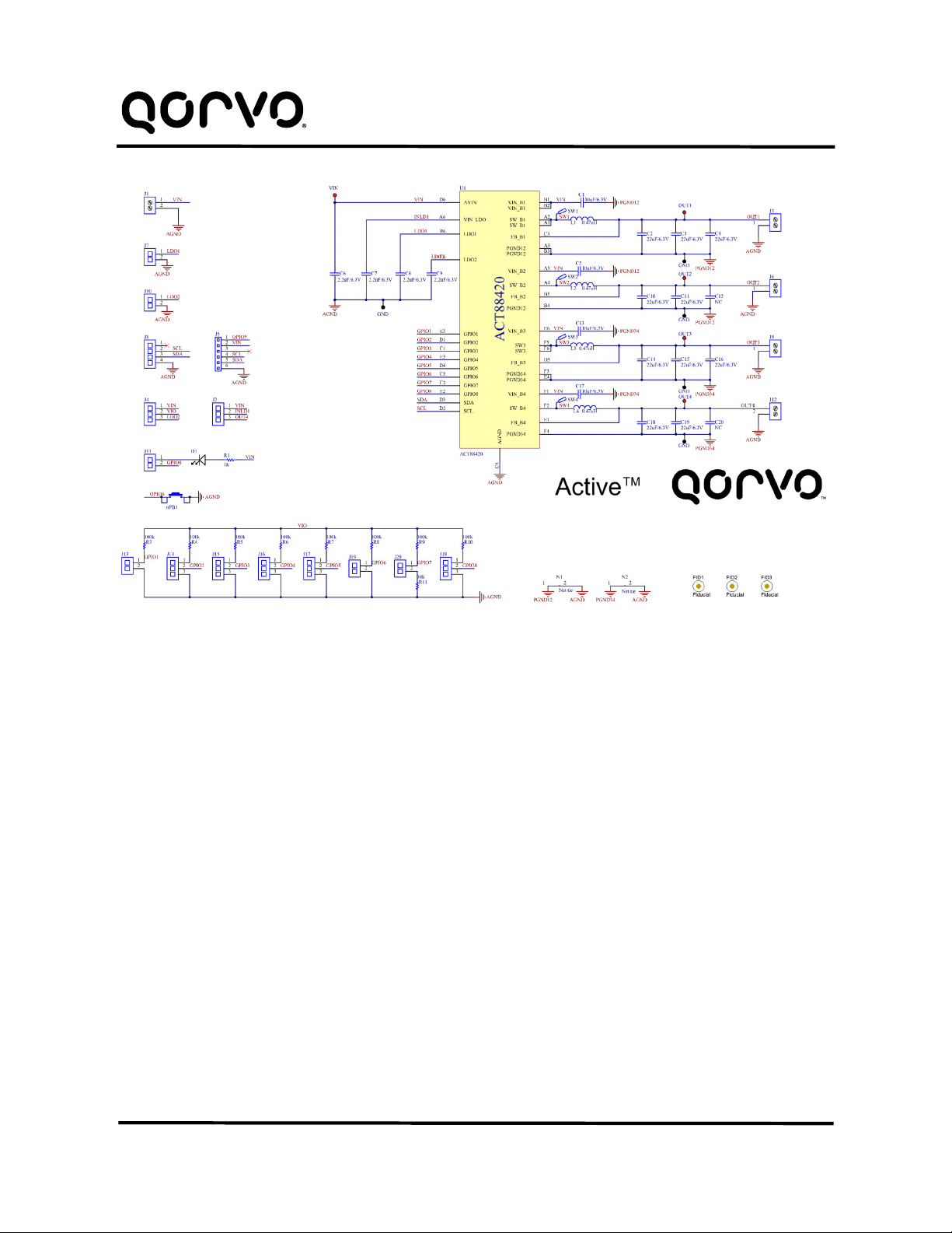
19 U1 1 IC, ACT88420-101T WLCSP36(6x6) Qorvo ACT88420-101T