qpcom QP-748MI Instructions for use

QP-748MI User Manual
Version 1.0
www.qpcom.com
Hardware User Manual
Industrial Managed Ethernet Switch
QP-748MI

QP-748MI User Manual
Version 1.0
www.qpcom.com
Contents
Overview ................................................................................................................................................. 1
Package Check List ............................................................................................................................ 1
Hardware Description ............................................................................................................................. 2
Front Panel Instruction...................................................................................................................... 2
Dimensions ......................................................................................................................................... 2
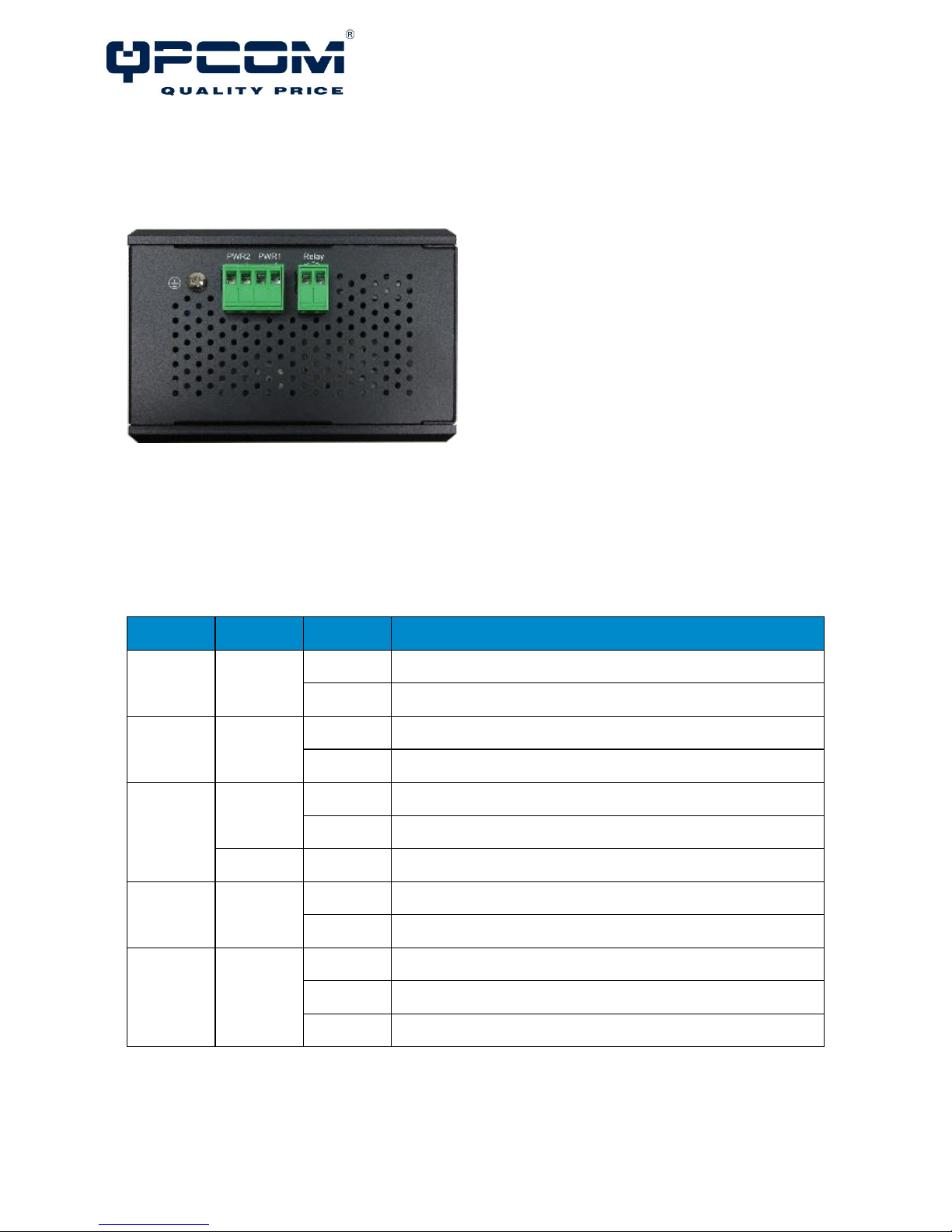
Top View ............................................................................................................................................ 3
LED Instruction................................................................................................................................... 3
Reset Button ...................................................................................................................................... 4
USB Port ............................................................................................................................................. 4
Hardware Installation ............................................................................................................................. 5
SFP Cabling......................................................................................................................................... 5
Wiring Power Inputs........................................................................................................................... 6
Wiring Fault Alarm............................................................................................................................. 7
Wiring Digital Inputs .......................................................................................................................... 7
Double-Secure Power Input Fault Alarm........................................................................................... 7
Mounting............................................................................................................................................. 8
Installation Steps ............................................................................................................................... 9
Specification .......................................................................................................................................... 10

QP-748MI User Manual
Version 1.0
1
Overview
This user manual is for QP-748MI is an industrial managed gigabit Ethernet switch with the following hardware
features:
Interface
▪MDI/MDI-X function supported on all copper ports
▪Embedded 8x Gigabit Ethernet ports + 4x 1000 SFP Slot
▪Store-and-forward switching architecture
Switch Properties
▪Up to 16K MAC Address Table supported
▪Up to 16000bytes Jumbo Frame supported
▪Up to 12Mbits Packet Buffer supported
Power Input
▪Redundant 12-48VDC power
Temperature
▪Standard operating temperature: -10°C ~ 60°C (14°F ~ 140°F)
▪Extended operating temperature: -40°C ~ 75°C (-40°F ~ 167°F)
▪Storage temperature: -40°C ~ 85°C (40°F ~ 185°F)
Mechanical Construction
▪Class IP30 protection
▪DIN-Rail Mounting, Optional Wall Mounting
PACKAGE CHECK LIST
The QP-748MI is shipped with the following items. Ensure that all the items are in the box. If any item
is missing or damaged, contact us for assistance.
▪QP-748MI switch x 1
▪Protective caps for 8x copper ports, 4x SFP slots, 1x USB port, and 1x RJ45 console port
▪User manual CD x 1
▪Wall mount brackets and screws (Optional)
▪RJ45 to RS232 Serial console cable x 1

QP-748MI User Manual
Version 1.0
2
Hardware Description
FRONT PANEL INSTRUCTION
The following picture is the front panel for "QP-748MI".
DIMENSIONS
WxHxD: 72x145x118 mm

QP-748MI User Manual
Version 1.0
3
TOP VIEW
This is the top view of the QP-748MI containing the
ground, power inputs, and fault alarm relay.
LED INSTRUCTION
System LEDs
LED
Color
Status
Description
PWR1
Green
On
Power is supplied on the power input 1.
Off
Power is not supplied on the power input 1.
PWR2
Green
On
Power is supplied on the power input 2.
Off
Power is not supplied on the power input 2.
Fault
Green
On
The system boots up and in normal operation.
Off
The system is powered off or during booting.
Red
On
The configured event of failure is triggered.
RM
Green
On
This device has the Ring Master.
Off
The Ring Master is not on the device.
Ring
Green
On
The Ring protocol is enabled and works normally.
Flickering
The Ring protocol is enabled, but works abnormally.
Off
The Ring protocol is disabled.

QP-748MI User Manual
Version 1.0
4
Interface Status LEDs
LED
Color
Status
Description
SFP Slot
P9 to P12
(1000M)
Green
On
The 1000Mbps link of the fiber port is active.
Flickering
Data is transmitted on the fiber port at 1000Mbps.
Off
The 1000Mbps link of the fiber port is inactive.
LAN Port
P1 to P8
(1000M)
Green
On
The 1000Mbps link of the port is active.
Flickering
Data is transmitted on the port at 1000Mbps.
Off
The 1000Mbps link of the port is inactive.
LAN Port
P1 to P8
(10/100M)
Green
On
The 10/100Mbps link of the port is active.
Flickering
Data is transmitted on the port at 10/100Mbps.
Off
The 10/100Mbps link of the port is inactive.
RESET BUTTON
A multifunctional reset button is provided. Use a pointed object such as toothpick or paper clip
(straightened) to press the reset button.
Continuous
Seconds
Action
1
Save the running configuration to the USB device named "running-config".
4
Reboot the system.
More than 7
Reset the system to factory default and reboot it.
USB PORT
A USB port is available on the switch that is located between the Console port and Reset
button. This USB port provides the following features:
▪Backup/Restore Configurations
▪Auto-Load configuration from USB
▪Auto-Backup configuration to USB
▪Save system logs to USB

QP-748MI User Manual
Version 1.0
5
Hardware Installation
SFP CABLING
There are 4x 1000 SFP Slot SFP Slots on the QP-748MIswitch. The 100Tx SFP module is not supported
in this model. The following table is the SFP modules that is recommend to the users.
Part No.
Wave
(nm)
Media
Power
(dBm)
Sen.
(dBm)
Code
Dist.
Temp.
1.25Gbps (Gigabit Ethernet/ 1000Base-X/ Fiber Channel SFP)
QPCOM-1000Base-X1
850
MMF
-9.5~-4
-17
SX
550m
0~70°C
QPCOM-1000Base-X2 (DDM)
1310
SMF
-9.5~-3
-20
LX
10km
0~70°C
QPCOM-1000Base-X3
1310
SMF
-9.5~-3
-20
LX
10km
-40~85°C
QPCOM-1000Base-X4 (DDM)
1310
SMF
-9.5~-3
-20
LX
10km
-40~85°C
1.25Gbps (1000Base-BX, Single Fiber Bi-Directional SFP)
QPCOM-1000Base-BX1 Dual-Rate
T1310
R1490
SMF
-9~-3
-20
1000BX10-U4
10km
0~70°C
QPCOM-1000Base-BX2 (DDM)
T1310
R1490
SMF
-9~-3
-20
1000BX10-U4
10km
-40~85°C
QPCOM-1000Base-BX3 Dual-Rate
T1490
R1310
SMF
-9~-3
-20
1000BX10-U4
10km
0~70°C
QPCOM-1000Base-BX4 (DDM)
T1490
R1310
SMF
-9~-3
-20
1000BX10-U4
10km
-40~85°C
Copper SFP (Gigabit Ethernet/1000BaseT)
QPCOM-1000Base-T
1.25Gbps
Copper
SFP-1000T-LOS
AutoNeg: On
100m
0~70°C
Insert SFP Module
1. Insert the SFP module. A triangle is available on the switch and SFP module.

QP-748MI User Manual
Version 1.0
6
2. Push the SFP module down.
Remove SFP Module
1. Press and remove the SFP cable.
2. Open the SFP module and remove it.
WIRING POWER INPUTS
1. Insert the positive and negative wires into the PWR1 (+,-) and PWR2
(+,-) on the 4-contact terminal block connector.
2. Tighten the screws to prevent the wires from loosening.

QP-748MI User Manual
Version 1.0
7
WIRING FAULT ALARM
1. Insert the wires into the left two contacts of the 4-contact terminal
block (Fault Alarm Relay).
2. Tighten the screws to prevent the wires from loosening.
3. The relay will detect the power and link failure.
4. Users can connect the relay to an alarm and buzzer so that when
the relay forms an open circuit, the users will be notified.
WIRING DIGITAL INPUTS
1. Insert the positive and negative wires into the right two contacts
(+,-) of the 4-contact terminal block (DI).
2. Tighten the screws to prevent the wires from loosening.
3. The system will detect the voltage go through the DI.
▪+13 to +30V for state "1"
▪-30 to +3V for state "0"
▪Max. input current: 8mA
DOUBLE-SECURE POWER INPUT FAULT ALARM
The power inputs are designed as a "common
negative", which implies that the negative input is
connected, but "double-secure" is supported to
prevent the unnotified failure of power from one of the
negative inputs. If one of the negative power input
fails, the system will detect it and the system will
trigger the event if the users set the fault alarm or
event log for powers.

QP-748MI User Manual
Version 1.0
8
MOUNTING
Din-Rail Mounting
a. Screw the DIN-Rail bracket to the switch.
b. Insert the top of the DIN-Rail bracket to the DIN-
Rail track.
c. Pull down the DIN-Rail bracket to the DIN-Rail track and check if it is mounted tightly on the DIN-Rail
track.

QP-748MI User Manual
Version 1.0
9
Wall Mounting
a. Remove the DIN-Rail bracket.
b. Screw the wall mount kits to the switch.
INSTALLATION STEPS
1. Unpack
The switch is well packed and shipped to our customers. Unpack it from the box.
2. Check Content Items
Please make sure all the items listed in the "Package Check List" are in the box.
3. Mounting
The DIN-Rail is screwed on the switch by default. If the DIN-Rail is not screwed to the switch, refer to
the "DIN-Rail Mounting" section to install it manually.
The Wall mount brackets are optional items. If you need the wall mount brackets, contact us for
assistance. To install the switch on the wall, refer to the "Wall Mounting" section.
4. Power On
To power on the switch, users must prepare a power supply and wire the power input. Refer to the
"Wiring Power Inputs" section.
The power LEDs are described in the "LED Instruction" section.
5. Connect
To connect to the switch, users need a RJ45 cable. Insert the RJ45 cable into one of the switch ports
and insert the other end to the host such as PC.
The link LEDs are described in the "LED Instruction" section.
6. Check LEDs
We recommend the users to check the status of LEDs in the "LED Instruction" section. If all the LEDs
are in the normal state, the installation is completed.

QP-748MI User Manual
Version 1.0
10
Specification
Technology
Standards
IEEE 802.3 10BaseT
IEEE 802.3u 100BaseTX
IEEE 802.3ab 1000BaseT
IEEE 802.3z 1000BaseX
IEEE 802.3x Flow Control
IEEE 802.3ad LACP
IEEE 802.1D Spanning Tree Protocol
IEEE 802.1w Rapid STP
IEEE 802.1s Multiple STP*
ITU-T G.8032 / Y.1344 ERPS
IEEE 802.1Q VLAN Tagging
IEEE 802.1ad Stacked VLANs
IEEE 802.1p Class of Service
IEEE 802.1X Network Authentication
IEEE 802.1AB LLDP
Processing Type
Store and Forward
Transfer Rate
14,880pps for Ethernet port
148,800pps for fast Ethernet port
1,488,000pps for gigabit Ethernet port
Transmission Distance
Up to 100M (Fast Ethernet)
Transmission Distance
Up to 1000Mbps
Switch Properties
Priority Queues
8 Queues
Jumbo Frame
16000bytes
MAC Table Size
16K

QP-748MI User Manual
Version 1.0
11
VLAN Table Size
4094
IGMP Group
1023
Packet Buffer
12Mbits
Interface
RJ45 Port
8x 10/100/1000T(x), auto negotiation speed duplex mode, auto
MDI/MDI-X
Fiber Port
4x 1000 SFP Slot
LED Indicators
Per unit: PWR1, PWR2, Fault, Ring Master, Ring State
Ports: Link/Active with highest speed(Green), low speed(Amber)
Alarm Contact
1x relay output with current carrying capacity of 1A @ 24 VDC
Digital Inputs
1x isolated input from the electronics.
+13 to +30V for state "1"
-30 to +3V for state "0"
Max. input current: 8mA
Button
Multiple functions reset button
Serial Console
1x RS232 in RJ45 connector with console cable, 115.2Kbps, 8N1
Storage
1x USB 2.0 storage for firmware update, configuration backup, restore,
boot up and syslog
Power Requirements
Operation Voltage
12-48VDC, redundant dual inputs
Connection
1x removable 4-contact terminal block
Power Consumption
17W
Protection
Overload Current Protected, Reverse Polarity Protected
Mechanical Construction

QP-748MI User Manual
Version 1.0
12
Enclosure
Aluminum
Protection Class
IP30
Dimensions
72x145x118 mm (WxHxD)
Weight
0.87 kg
Mounting
DIN-Rail Mounting, Optional Wall Mounting Kits
Environmental Limits
Operating Temperature
Standard: -10°C ~ 60°C (14°F ~ 140°F)
Extended: -40°C ~ 75°C (-40°F ~ 167°F)
Storage Temperature
-40°C ~ 85°C (40°F ~ 185°F)
Ambient Relative Humidity
5 to 95%, (Non-Condensing)
Regulatory Approvals
EMI
FCC Part 15 Subpart B Class A
CE EN 55022 Class A
EMS
IEC61000-4-2 (ESD Level 4)
IEC61000-4-3 (RS Level 3)
IEC61000-4-4 (EFT Level 4)
IEC61000-4-5 (Surge Level 4)
IEC61000-4-6 (CS Level 3)
IEC61000-4-8 (Magnetic Field Level 4)
Free Fall
IEC60068-2-32
Shock
IEC60068-2-27
Vibration
IEC60068-2-6
Green
RoHS Compliant

QP-748MI User Manual
Version 1.0
13
Certifications
UL 60950-1/62368 (Pending)
MTBF
>100,000 hours
Warranty
3 Years
Table of contents
Other qpcom Network Router manuals
Popular Network Router manuals by other brands

TP-Link
TP-Link TL-WA860RE Quick installation guide

MikroTik
MikroTik RouterBOARD 411U Quick setup guide and warranty information

Patton electronics
Patton electronics OnSite 2800 Series quick start guide

Vimar
Vimar ELVOX TVCC 46260.10P.02 Installer's guide

honor
honor Router 3 quick start guide

Netopia
Netopia 3347NWG-VGx Quick start installation guide