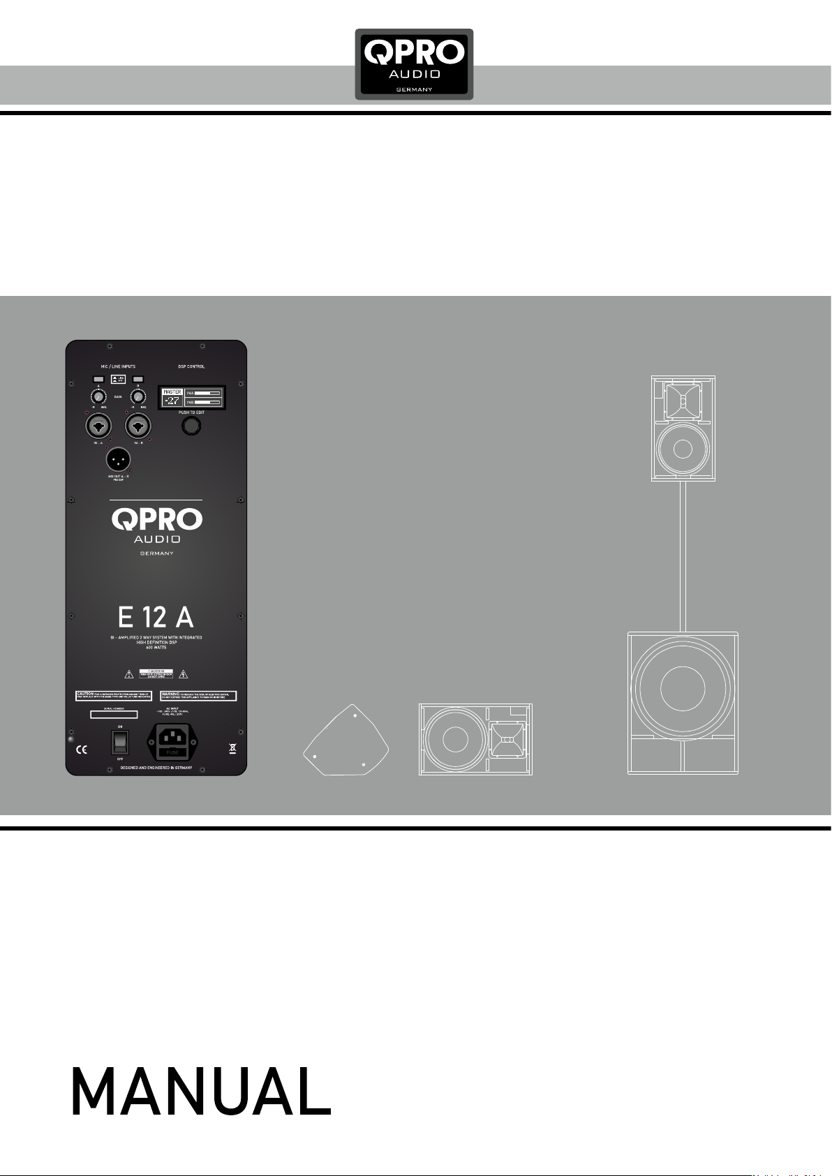
DSP Functions
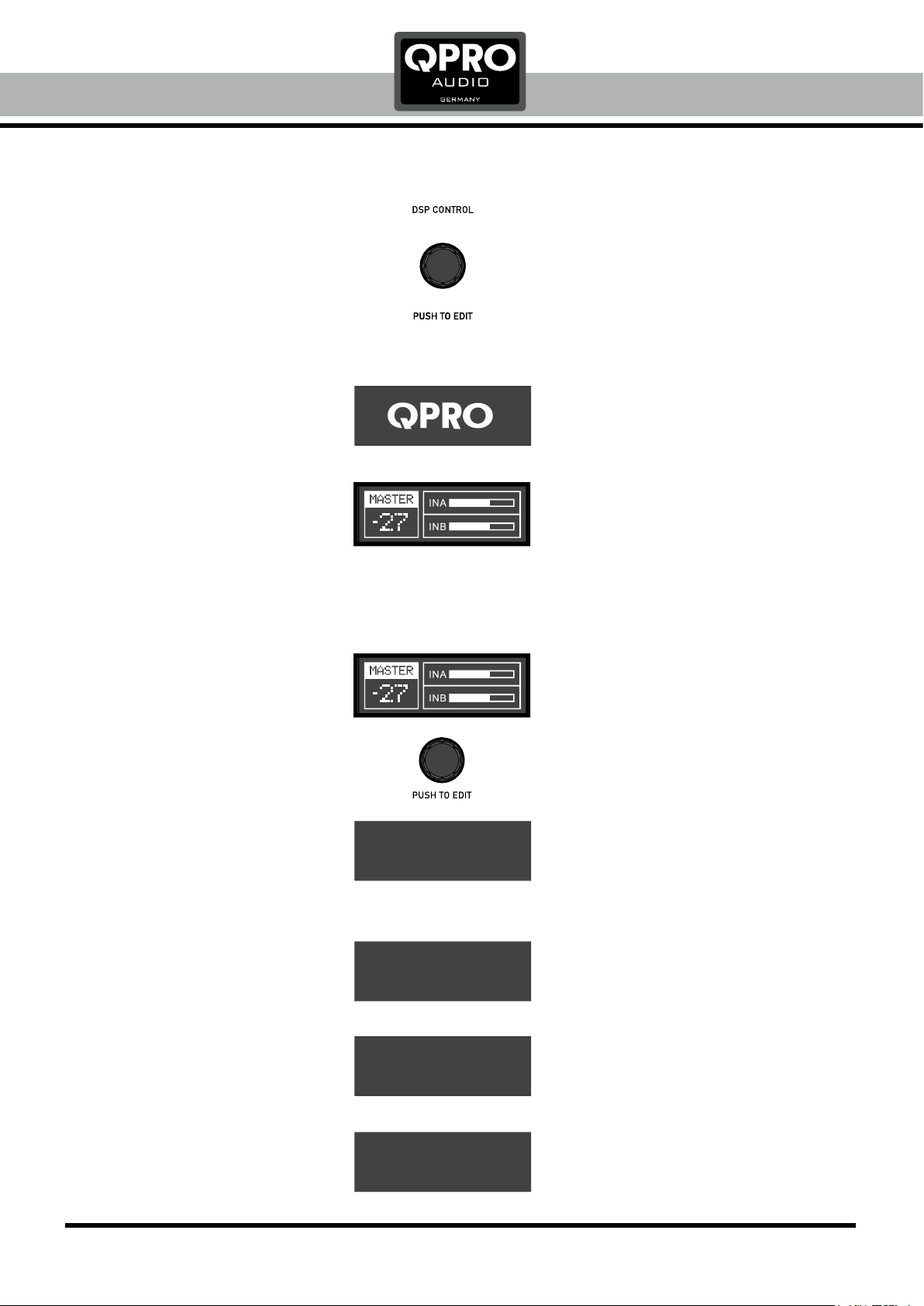
DSP ENCODER / CONTROLLER
The encoder is an endless data wheel with push
function to enter menus and confirm settings.
With this encoder the whole DSP can be controlled.
BEFORE SWITCH ON
Take care, that the correct input mode is selected.
Turn both gain controllers to left position.
After s E-Series QPROwitch ON the speaker the
logo will be displayed for some seconds.
The display shows the home screen
after initializing.
MASTER VOLUME
The default setting is +00 position. Turn the red DSP
controller to change the master volume (from -60 up to +10).
INPUT GAIN SETTING
Set the input gain of both input channels with the
gain controls. If the display shows CLIP, reduce the
gain of the clipping input.
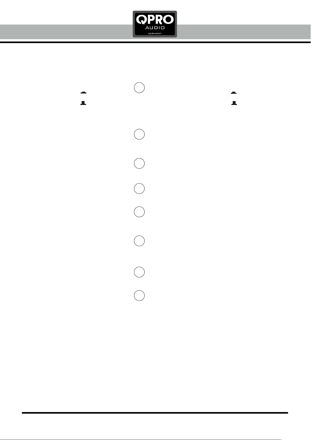
DSP FUNCTIONS
Press the gain controller to enter the DSP menu.
Press and rotate the DSP controller to edit the
3-band EQs (+/- 12dB).
MODE (sound modes): MUSIC, VOICE, DJ, MONITOR
LOW CUT: OFF, 80Hz, 100Hz, 120Hz, 150Hz
LCD DIM: Switch ON or OFF the display dim function
BRIGHT: Set the brightness of display
CONTRAST: Set the contrast of display
RESET: Reset to factory default settings
INFO: Shows version of DSP
EXIT: Back to home screen
DSP ENCODER / CONTROLLER
Der Encoder ist ein Endlos-Stellrad mit Drück-Funktion,
um in alle Menüs zu gelangen und Einstellungen zu Bestätigen.
Mit diesem Encoder wird der gesamte DSP gesteuert.
VOR DEM EINSCHALTEN
Vor dem Einschalten des Lautsprecher sollte beachtet werden,
dass der korrekte Modus am Eingang gewählt ist.
Stellen Sie beide Gain Regler in die linke Position bis Anschlag.
Nach dem Einschalten des Lautsprechers erscheint das
QPRO Logo für wenige Sekunden im Display
Nach der Initialisierung zeigt das Display den Home
Screen an.
MASTER LAUTSTÄRKE
Die Werkseinstellung ist justiert auf +00 Position. Mittels
Drehen des DSP Controllers kann die Master Lautstärke
eingestellt werden (von -60 bis zu +10).
INPUT GAIN EINSTELLUNG
Das Gain beider Eingänge kann mittels der Gain Regler
eingestellt werden. Zeigt das Display CLIP an, muss das
Gain des übersteuerten Eingangs reduziert werden.
DSP FUNKTIONEN
Durch Drücken des roten DSP Controllers gelangt man in
das DSP Menü.
Durch Drücken und Drehen des DSP Controllers kann
nun der 3-Band EQ eingestellt werden (+/- 12dB).
MODE (Soundprogramme): MUSIC, VOICE, DJ, MONITOR
LOW CUT (Hochpass): OFF, 80Hz, 100Hz, 120Hz, 150Hz
LCD DIM: Einstellung der Display-Dimmer-Funktion
BRIGHT: Justage der Display-Helligkeit
CONTRAST: Justage des Display-Kontrasts
RESET: Rücksetzung auf Werkseinstellungen
INFO: Zeigt die DSP Version an
EXIT: Zurück zum Home Screen
+03 dB
0 dB
+01 dB
HIGH EQ:
MID EQ:
LOW EQ:
MUSIC
OFF
MODE:
LOW CUT:
OFF
5
5
LCD DIM:
BRIGHT:
CONTRAST:
RESET
INFO
EXIT