QSC DCP 300 User m Instructions for use

TD-000285-00 rev. 005
Digital Cinema
Hardware User Manual
DCP 300 – Digital Cinema Processor

1
IMPORTANT SAFETY PRECAUTIONS & EXPLANATION OF SYMBOLS
The lighting flash with arrowhead symbol within an equilateral triangle is intended to alert the
user to the presence of uninsulated “dangerous” voltage within the product’s enclosure that
may be of sufficient magnitude to constitute a risk of electric shock to humans.
The exclamation point within an equilateral triangle is intended to alert the user to the
presence of important operating and maintenance (servicing) instructions in this manual.
SAFEGUARDS
Electrical energy can perform many useful functions. This unit has been engineered and
manufactured to assure your personal safety. Improper use can result in potential electrical
shock of fire hazards. In order not to defeat the safeguards, observe the following instructions
for its installation, use and servicing.
Caution: To reduce the risk of electric shock, do not remove the cover. No user-serviceable
parts inside. Refer servicing to qualified service personnel.
Warning: To prevent fire or electric shock, do not expose this equipment to rain or moisture.
1 – Maximum operating ambient temperature is 50°C (122°F).
2 – Never restrict airflow through the device vents. Please insure that the side panel vents are
unobstructed.
3 – When installing equipment into rack, distribute the units evenly. Otherwise, hazardous
conditions
could be created by an uneven weight distribution.
4 – Connect the unit only to a properly rated supply circuit. The DCP 300 is suitable for
connection to
100-240VAC, 50-60Hz with no special considerations other than the appropriate IEC power
cord.
5 – Reliable Earthing (grounding) of rack-mounted equipment should be maintained.
LITHIUM BATTERY WARNING
THE DCP 300 EQUIPMENT CONTAINS A NON-RECHARGEABLE LITHIUM BATTERY.
LITHIUM IS A CHEMICAL KNOWN TO THE STATE OF CALIFIRNIA TO CUASE CANCER OR
BIRTH DEFECTS. THE NON-RECHARGEABLE LITHIUM BATTERY CONTAINED IN THIS
EQUIPMENT MAY EXPLODE IF IT IS EXPOSED TO FIRE OR EXTREME HEAT. DO NOT SHORT
CIRCUIT THE BATTERY. DO NOT ATTEMPT TO RECHARGE THE NON-RECHARGEABLE
LITHIUM BATTERY.

2
WARRANTY (USA only; other countries, see your dealer or distributor)
Disclaimer
QSC Audio Products, LLC (“QSC”) is not liable for any damage to amplifiers, loudspeakers, or other equipment
that is caused by negligence or improper installation and/or use of this signal processing product. While QSC
has endeavored to develop and produce the most dependable and robust ‘network’ audio product for your use,
due to the myriad of network situations and equipment that may be encountered in its implementation, QSC
cannot be held responsible for network conflicts and associated consequences that may result. For this reason,
QSC strongly recommends that the network used for implementation of the DCP 300 product(s) be completely
separate from all other networks, data or otherwise. As such, should you elect to integrate the DCP 300
product(s) with an existing network system, all risks attendant to such integration of the DCP 300 product(s) with
an existing network or network systems are assumed by you. While QSC strives to provide the highest quality
technical solutions for networked audio products, in no event will QSC or its suppliers be held liable for any
damage, consequential, incidental or otherwise, including any claims for lost profits and/or savings resulting from
any attempted integration of the DCP 300 product(s) with an existing network or network system. No agent,
employee or representative of QSC has any authority to alter or modify in any manner, the disclosures and
recommendations set forth herein.
QSC Audio Products 3-Year Limited Warranty
QSC Audio Products, LLC (“QSC”) guarantees the DCP 300 product to be free from defective materials and/or
workmanship for a period of three (3) years from the date of sale and will replace defective parts and repair
malfunctioning products under this warranty when the defect occurs under normal installation and use –
provided the unit is returned to our factory or one of our authorized service stations via prepaid transportation
with a copy of proof of purchase (i.e., sales receipt). This warranty provides that the examination of the returned
product must indicate, in our judgment, a manufacturing defect. This warranty does not extend to any product
which has been subjected to misuse, neglect, accident, improper installation, or where the date code has been
removed or defaced. QSC shall not be liable for incidental and/or consequential damages. This warranty gives
you specific legal rights. This limited warranty is freely transferable during the term of the warranty period.
Customers may have additional rights, which vary from state to state.
In the event that this product was manufactured for export and sale outside of the United States or its territories,
then this limited warranty shall not apply. Removal of the serial number on this product, or purchase of this
product from an unauthorized dealer will void this limited warranty.
Periodically, this warranty is updated. To obtain the most recent version of QSC’s warranty statement, please
contact us at 800-854-4079 or visit our website at www.qscaudio.com.
FCC INTERFERENCE STATEMENT
NOTE: This equipment has been tested and found to be in compliance with the limits for a class B digital device,
pursuant to part 15 of the FCC rules.
These limits are designed to provide reasonable protection against harmful interference in a residential
installation. This equipment generates, uses, and can radiate radio frequency energy and if not installed and
used in accordance with to the instructions, may cause harmful interference to radio communications. However,
there is no guarantee that interference will not occur in a particular installation. If this equipment does cause
harmful interference to radio or television reception, which can be determined by switching the equipment on
and off, the user is encouraged to try to correct the interference by one or more of the following measures:
•Reorient or relocate the receiving antenna.
•Increase the separation between the equipment.
•Connect the equipment into an outlet on a circuit different from that to which the receiver is
connected.
•Consult the dealer or an experienced radio or TV technician for help.

3
TRADEMARK AND COPYRIGHT NOTICES
© 2009, QSC Audio Products, LLC. This Hardware User Manual and the content therein is protected by copyright law. No part of
this Hardware User Manual may be reproduced, printed, edited, or re-transmitted, or stored in a document retrieval system for the
purpose of re-distribution, without the permission of QSC Audio Products, LLC
QSC is a registered trademark of QSC Audio Products, LLC
“QSC” and the QSC logo are registered with the US Patent and Trademark office
QSControl, QSCreator, DCP Manager, Digital Cinema Amplifier (DCA), Digital Cinema Processor (DCP), BASIS, RAVE, and
“Intrinsic Correction” are trademarks of QSC Audio Products, LLC
USA and Foreign Patents Pending.
“Windows” is a trademark of Microsoft Corp. Dolby is a registered trademark of Dolby Laboratories. DTS is a registered trademark
of DTS, Inc. “CobraNet” and the CobraNet logo are trademarks of Cirrus Logic, Inc. All other trademarks are the property of their
respective owners.
RoHS STATEMENT
The DCP 300 product is in compliance with European Directive 2002/95/EC – Restriction of hazardous Substances (RoHS).
The DCP 300 product is in compliance with “China RoHS” directives. The following chart is provided for product use in China and
its territories:

4
Introduction
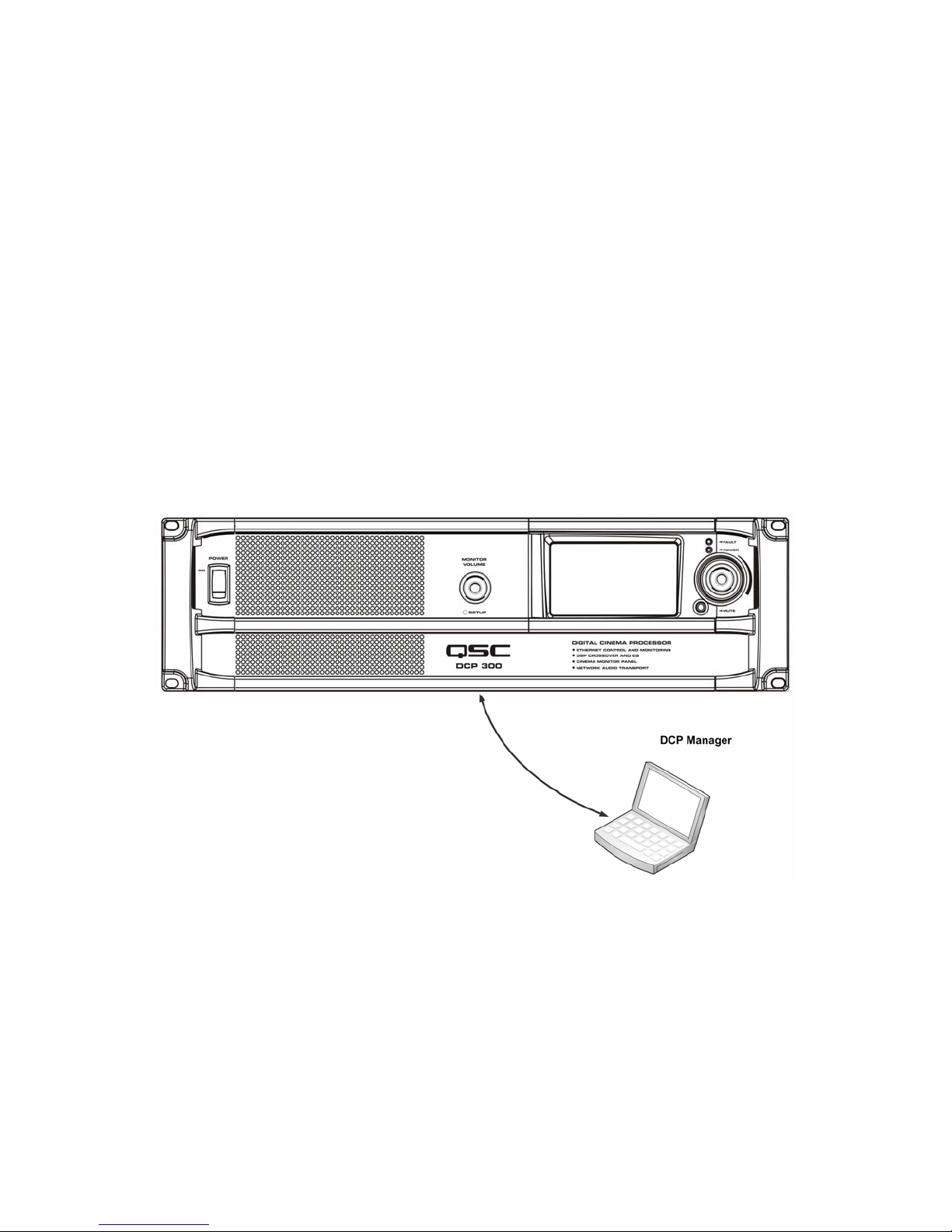
QSC’s DCP 300 is a powerful solution for today’s D-Cinema
audio systems. From server to speakers, the DCP 300
offers a complete set of tools to facilitate all the signal
processing, audio distribution, monitoring and automation
control services required in a modern D-Cinema sound
system.
The DCP 300 builds on the legacy of QSC's DCM and Basis
products to provide all signal processing and monitoring
functions for Digital Cinema in a single integrated system.
Designed to be used with QSC's Digital Cinema Amplifiers
(DCA) and featuring advanced DSP presets for QSC's
Digital Cinema Speakers (DCS), the DCP 300 optimizes
loudspeaker performance while simplifying cinema sound
system wiring and configuration. The DCP 300 covers
cinema systems ranging from three to five screen channels,
and is configurable for bi-amp, tri-amp or quad-amp
operation. Though optimized to receive audio content
directly from a D-Cinema server, the DCP 300 is also
compatible with all analog cinema processor formats
including Dolby® Digital Surround-EX and DTS-ES and
features a 10 channel analog input for integration with
35mm audio systems.
The DCP 300 is more than an audio processor. Whether
designing a system with a single auditorium or designing a
large multiplex, the DCP 300 offers the flexibility in
configuration, networking, audio distribution and advanced
management services to get the job done.
Features
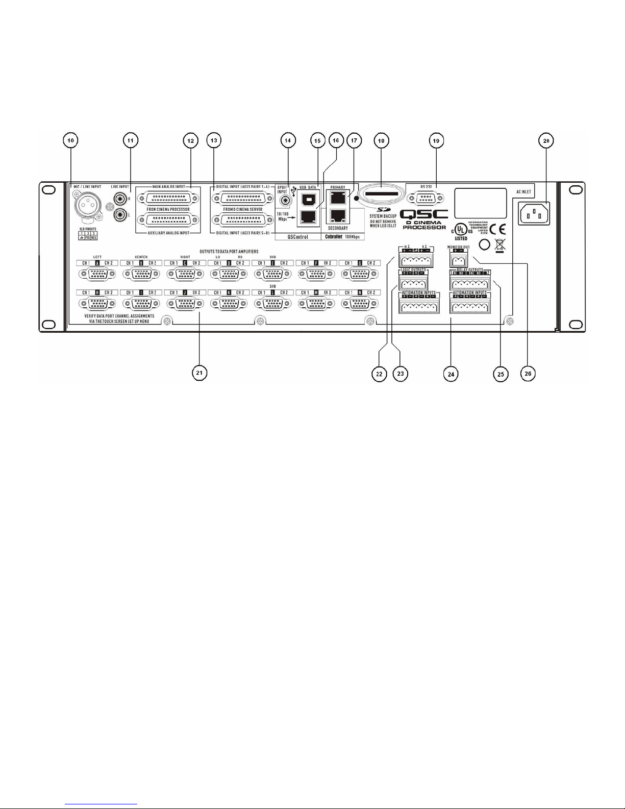
•Digital inputs accept up to 16 channels of audio (AES-3)
from a D-Cinema server or other digital source
•Networked audio I/O via CobraNet™
•Analog inputs accept audio from film processors
•Additional analog inputs accommodate non-sync and
Mic/Line sources
•Master volume and full 1/3 octave EQ on all channels
(except subwoofer)
•Booth monitor with touch screen control for easy
operation
•Digital loudspeaker crossovers
•Three or five screen channels – 2, 3 or 4-way crossovers
•Compatible with all existing QSC DCA amplifiers
•Dual internal power supplies with load sharing for
seamless recovery in the event of a failure
•SD memory card for quick unit swap – restores all
settings (not yet supported: expected Winter 2009)
•Multiple bypass modes - routes audio around failed
components to ensure that the show will go on
•DSP presets for QSC’s DCS speakers for great “out of the
box” performance and reduced setup time
•Crossovers support active 2, 3 or 4-way systems
•QSControl.net suite of applications (including Venue
Manager, QSCreator, Notify and API for 3rd Party control
systems) offer ultimate flexibility in management and allow
for the creation of custom control screens, remote access,
fault reporting and diagnosis
•Easily integrates with existing film processors for dual
film/digital projection systems
•CobraNet™ offers digital non-sync routing and future
expansion capability
•Continued development of software and firmware will add
new capabilities to the existing hardware with easy updates
•The DCP 300 is the heart of a new generation of QSC
products designed expressly for the needs of D-Cinema
sound systems
Digital Signal Processing
The DCP 300 digital signal processing capability outperforms
traditional analog crossovers and equalizers for optimized
speaker performance. Crossover frequency, 1/3 octave graphic
EQ, parametric equalization, polarity, delay and gain can be
precisely adjusted for each speaker in your system. Active 2-
way, 3-way and 4-way crossovers are available. Advanced
crossover presets for QSC DCS speakers speeds system set-
up and insures maximum performance.
Less Wiring, Faster Setup
The DCP 300 greatly simplifies system wiring and set-up,
significantly reducing installation time and labor cost. Input to
the DCP 300 is provided via standard DB-25 cables from the
D-Cinema server and/or 35mm cinema processor. Connections
to DCA amplifiers for input and monitor signals are made
through a single QSC Dataport / VGA-style cable. All traditional
XLR and barrier strip terminations are eliminated. DCP 300s
simplify set-up by using a menu-driven, PC-based software
program for configuration. The program includes a speaker
data file that lists default parameters for popular cinema
speaker models. Commonly used configurations can also be
saved on a disk, or redistributed across a network, allowing you
to quickly load them into other DCP 300s throughout a theatre
complex. All system configuration data is saved to an SD
memory card, allowing easy transfer of settings to a new
(backup) DCP 300, should replacement ever be required (SD
functionality is not yet supported: expected Winter 2009)
Advanced Monitor Functions
In addition to audio monitoring of amplifier inputs and outputs,
the DCP 300 includes QSC's exclusive "load fault" detection.
The DCP 300 monitors all amplifier outputs and indicates
opens and shorts in the speaker system, providing confirmation
that all amplifier outputs are functioning properly. In addition,

5
the DCP 300 detects all amplifier clipping, protect modes
and heat sink temperature for reporting via a QSControl
Ethernet monitoring system. The QSControl.net suite of
applications allows for the creation of custom control
screens via “drag and drop” design using the QSCreator
software application.
Screens can be designed to provide intuitive fault reporting and
diagnosis that is accessible through remote network access. In
addition, QSC’s PoE enabled NAC 100 Ethernet remote control
panel provides remote operation and status throughout a
cinema multiplex from anywhere on the local network.
DCP 300 Front Panel Features
1. Power “on” switch
2. Monitor volume and parameter adjust (this control has two modes of operation)
Speaker mode: controls level to DCP 300 front panel speaker in monitor mode
Setup mode: provides parameter control and LCD navigation in setup mode
3. Touch control LCD (4.3” 16:9 color display)
4. Power “on” LED – illuminates green when AC power is applied
5. Fault LED – illuminates red when load faults or system errors are detected
6. 4” full range monitor speaker
7. Setup mode LED – illuminates green when DCP 300 is in setup mode
8. Mute button – illuminates red when engaged, illuminatesgreen during normal operation
9. Auditorium volume control – global level control for all Dataport outputs

6
DCP 300 Rear Panel Features
10. Mono analog input – accepts microphone or line level signals (w/ phantom power)
11. Stereo analog inputs – accepts line level signals
12. Analog audio inputs – connect to D-Cinema server or film processor with analog outputs
Top connector: channels 1 through 8
Bottom connector: 8 auxiliary channels
13. Digital audio inputs – connect to D-Cinema server or film processor with digital outputs
Top connector: AES3 pairs 1 through 4 (digital audio channels 1 through 8)
Bottom connector: AES3 pairs 5 through 8 (digital audio channels 9 through 16)
14. S/PDIF input – multi-channel digital input for non-synch/alternative content
15. USB slave/client port for DCP 300 configuration and management via direct connection
16. 10/100 Mbps Ethernet port – for QSControl management and remote access
17. 100 Mbps Ethernet ports – CobraNet audio network - Primary and Secondary (backup)
18. SD memory card – device configuration storage
19. Serial communications port – 3rd party control/automation via RS232
20. IEC inlet – AC mains power connector with cord lock
21. Dataport interface for QSC amplifiers – fourteen connectors (up to 28 channel outputs)
22. Hearing impaired and visually impaired special mix outputs
23. TTL logic outputs – for use as automation triggers, alerts, system status flags etc.
24. Automation inputs – digitally sampled analog control inputs (control presets, levels etc.)
25. Relay outputs – mechanically decoupled control outputs (curtain, lighting control etc.)
26. Audio monitor output – line level tap from front panel monitor speaker (post DSP, pre amplifier)

7
Configuration and Networking
The DCP 300 offers a variety of accessibility options for
configuring and managing the product and an entire cinema
sound system locally or remotely. Local DCP 300
configuration and system management are provided through
directly applied connections to the DCP 300 via universal
serial bus (USB), the DCP 300 front panel touch-control
LCD or through a local Ethernet link (QSControl). Remote
and system-wide management are possible through more
sophisticated network implementations and/or via wide area
network (WAN) topologies, Internet access or 3rd party
subscription services that make use of the DCP 300 3rd
party API.
Basic configuration of the DCP 300 product is performed
through the USB interface on the product rear panel. The
system designer connects to the DCP 300’s rear panel USB
port with a Windows laptop or PC running the DCP Manager
software application. DCP Manager offers all the setup
tools and system management objects needed to configure the
auditorium audio format, selection of audio source material,
configure the DSP signal path, apply crossovers and EQs,
define the routing of audio to the amplifiers, define the system
speakers and speaker processing etc. Once the basic
configuration is complete, the system designer can define
custom "Presets"that can be recalled for different auditorium
setups. For example, a Preset can be created for the primary
presentation content. Another can be created for non-sync or
alternative content. And yet another can be created for live
application use such as seminars or corporate events. Once
these Presetsare created they become accessible via the DCP
300 front panel touch-control LCD.
In addition to basic configuration, DCP Manager can be used to
monitor health, status and performance of the local system (the
directly connected DCP 300) via the product rear panel USB
interface.
USB connection to DCP 300
The image above illustrates a Windows laptop connecting directly to the DCP 300 via the product rear panel USB interface. The
Windows machine is running QSC’s DCP Manager Application.

8
Once the DSP signal chain and audio format are configured,
the DCP 300 can be connected to an Ethernet LAN for local
or remote management using the QSControl.net suite of
applications or using the DCP 300 3rd Party API.
A local Ethernet connection to a Windows laptop or PC that
is running QSC’s Venue Manager Application provides the
system designer with access to status, health and
performance of the local system. Changes to Presets, audio
levels and some automation control objects can be made
through Venue Manager access. DCP 300 firmware updates
can also be performed through the Venue Manager
Application.
For more venue-specific needs, QSC’s QSCreator Application
allows the system designer to create custom control screens
with varying levels of password protection (authentication
rights). QSCreator screens can be as elaborate as the system
designer’s imagination and can be created to depict the
physical layout of the auditorium or the entire cinema complex
Since the QSControl.net suite of applications provide
accessibility to the DCP 300’s the network interface, these
applications can be used to manage an entire sound system
consisting of multiple DCP 300 products, QSC amplifiers,
speakers and other QSC networked-enabled products such as
BASIS, RAVE and DSP 300 series products. Management can
be localized (within the theatre complex) or remote, depending
on the network implementation deployed.
Local Ethernet connection to DCP 300
The image above illustrates a Windows laptop connecting directly to the DCP 300 via the product rear panel QSControl interface. The
Windows machine is running QSC’s QSControl.net suite of applications (Venue Manager, QSCreator, Notify, 3rdParty API etc.).

9
Unpacking:
There are no special unpacking precautions. However, it is
recommended that you keep the original packing materials
for reuse in the rare event that service is required. If service
is required and the original packing material is not available,
ensure that the unit is adequately protected for shipment
(use a strong box of appropriate size, sufficient
packing/padding material to prevent load shifting or impact
damage) or call QSC’s Technical Services Group for
replacement packing material and a carton.
DCP 300 product carton contents:
1. DCP 300 product
2. Rubber feet
3. Hardware Manual
4. DCP Manager software CD
5. AC power cord and retaining wire
6. Automation and control connector plug kit
Mounting:
The DCP 300 product can be used in or out of an equipment
rack. Rack mounting is optional. Adhesive rubber feet are
included for non-rack mount installations (table of shelf top
installations). Use the feet to prevent the unit from
scratching or marring the support surface.
Rack mount the DCP 300 product by supporting it from
underneath while aligning the four front panel mounting holes
(in the rack ears) with the threaded screw holes in the rack
rails. Install all four mounting screws and washers and tighten
securely. The DCP 300 product comes with rear rack support
ears. Ensure that these rear mounting points are securely
fastened to rear rack rails or side walls.
Computer Requirements & Software Installation:
Installing the DCP Manager and QSControl.net* suite of
software applications is easy. All you need to do is choose
the folder where the application is to reside (the default
setting is acceptable for most users). We recommend your
system meet the following minimum requirements:
1. IBM PC compatible computer (Windows PC)
2. Intel Pentium 4 CPU or better
3. CPU speed of 2.0 GHz or faster
4. 1 GB of RAM or greater
5. Hard drive with at least 1 GB of space available
6. Display resolution of at least 1024x768
7. CD-ROM drive for installing DCP 300 software
8. Network Interface Card (10/100/1000 Mbps)
9. OS: Windows XP Pro, Windows Vista, Windows 7
WARNING!!!
The DCP Manager software must be installed
before connecting the DCP 300 product to a
computer’s USB port
Installing DCP Manager Software:
1. Start your PC or laptop
2. Close any running applications
3. Place the DCP Manager Software CD into your CD-
ROM/DVD drive.
4. The software should auto-run. If not, select “run” from
the “start” menu. Browse to the file named “setup.exe”
on your CD-ROM/DVD drive.
5. Click the “Install DCP Manager Software” button
6. Follow the on-screen prompts/instructions
* Contact QSC’s Technical Services Group for instructions on downloading the latest compatible
version of QSControl.net software for managing your DCP 300 over an Ethernet LAN.

10
Connections:
AC Power Cord
Insert the molded receptacle of the AC power cord into the AC power inlet on the back of
the DCP 300 product. Plug the AC line connector into an AC outlet. The power supply on
the DCP 300 product will accept from 100 to 240V, 50 to 60 Hz. If a different type of IEC
power cord is required than that supplied with the product, consult QSC’s Technical
Services Group.
Dataports
The QSC Dataport connectors on the DCP 300 rear panel are intended to interface to
QSC amplifiers equipped with mating v1 Dataport connectors. These are the “all-
capable” Dataports compliant with QSC’s version 1 Dataport specification. V1 Dataports
are included on all DCA and PL3 series amplifiers. QSC Dataports use the HD15
“female” connector format. Connections between the DCP 300 and QSC amplifiers
require 15-conductor cables with “male” HD15 plugs on both ends. These are commonly
referred to as VGA cables. Note: though many off-the-shelf VGA cables “may” work with
satisfactory results, the QSC Dataport specification requires that all 15 conductors be
present and that all audio I/O conductors be shielded. Therefore, only QSC supplied
Dataport cables should be used in order to ensure the best possible signal quality and
audio performance. A variety of cable lengths are available through QSC’s Technical
Services Group.
To connect a Dataport cable between a DCP 300 Dataport and an amplifier Dataport,
attach the cable’s male plug to the HD15 female receptacle on the DCP 300 or amplifier
and finger tighten the thumb screws on the cable.
H.I. and V.I. Outputs
The hearing impaired and visually impaired special mix outputs are balanced outputs that
are combined into a single 5-terminal Euro style (a.k.a. Phoenix) receptacle. This combo
receptacle includes a common ground for both the H.I and V.I. outputs. Terminate the
mating 5-terminal Euro plug and insert it into the DCP 300 rear panel receptacle as
shown in the image. The DCP 300 rear panel label provides a pinout of the receptacle
signals. Note: a standard 3-terminal plug may be used if only one output is required.
Single-ended Balanced Z
combo plug

11
Connections:
Automation Inputs, Logic Outputs, Monitor Output
The automation inputs, logic outputs and monitor output all use a 2-terminal Euro style
(a.k.a. Phoenix) receptacle. The Automation Inputs can be connected to relay contacts, a
switch or a 10K potentiometer. Logic Outputs are CMOS compatible. And the Monitor
Output is a single-ended balanced impedance source. All connections require a 2-terminal
Euro style plug. The DCP 300 rear panel label provides all necessary signal information.
The negative terminal of each receptacle is at chassis potential.
Relay Outputs
Two relay outputs are provided via two 3-terminal Euro style (a.k.a. Phoenix) receptacles.
Relay contacts are floating and rated for 30 VDC at 1A. Each output includes one common
terminal, one normally open contact (N.O.) and one normally closed (N.C.) contact. These
terminals are labeled “C”, “NO” and “NC”, respectively on the DCP 300 rear panel. When
the relay is not energized, the “C” terminal is connected to the “NC” contact and the “NO”
contact is not connected. When the relay is energized, the “C” terminal is connected to the
“NO” contact and the “NC” contact is not connected.
QSControl Network
Connect one end of a data communications cable terminated with an RJ45 plug into the
“QSControl” receptacle on the rear panel of the DCP 300 product. Ensure that the lock tab
on the cable engages with the RJ45 receptacle on the DCP 300 rear panel connector.
Note: data communications cabling must be rated CAT-3 or better for 10 Mbps network
connections or rated CAT-5 or better for 100 Mbps network connections.
CobraNet Network
Connect one end of a data communications cable terminated with an RJ45 plug into the
“CobraNet Primary” receptacle on the rear panel of the DCP 300 product. Ensure that the
lock tab on the cable engages with the RJ45 receptacle on the rear DCP 300 panel
connector. For systems requiring redundant network connections, connect a second data
communications cable terminated with an RJ45 plug into the “CobraNet Secondary”
receptacle on the rear panel of the DCP 300 product. Note: data communications cabling
must be rated at CAT-5 or better for all CobraNet connections.

12
Connections:
Main Analog Input Connector Pinout:
25-pin male Sub-D to 25-pin male Sub-D
Pin #
1
2
3
4
5
6
7
8
9
10
11
12
13
Description
Chassis ground
Left +
Left Center –
Chassis ground
Center +
Right Center –
Chassis ground
Right +
Chassis ground
Surround Left –
Surround Right –
Subwoofer –
Chassis ground
Pin #
14
15
16
17
18
19
20
21
22
23
24
25
Description
Left –
Chassis ground
Left Center +
Center –
Chassis ground
Right Center +
Right –
(not used)
Chassis ground
Surround Left +
Surround Right +
Subwoofer +
Auxiliary Analog Input (Surround EX) Pinout:
25-pin male Sub-D to 25-pin male Sub-D
Pin #
1
2
3
4
5
6
7
8
9
10
11
12
13
Description
(not used)
(not used)
Back Surr Lt –
(not used)
(not used)
Back Surr Rt –
GND Dig Inputs
(not used)
Right Extra +
Surr Left –
Surround Right –
(not used)
(not used)
Pin #
14
15
16
17
18
19
20
21
22
23
24
25
Description
Left Extra +
Left Extra –
Back Surr Lt +
(not used)
(not used)
Back Surr Rt +
(not used)
(not used)
Right Extra –
Surround Left +
Surround Right +
(not used)
Digital (AES3) Input Connector Pinout:
25-pin male Sub-D to 25-pin male Sub-D
Pin #
1
2
3
4
5
6
7
8
9
10
11
12
13
Description
AES 1: Gnd
AES 1: Neg
AES 2: Pos
AES 3: Gnd
AES 3: Neg
AES 4: Pos
(not used)
(not used)
(not used)
(not used)
(not used)
(not used)
(not used)
Pin #
14
15
16
17
18
19
20
21
22
23
24
25
Description
AES 1: Pos
AES 2: Gnd
AES 2: Neg
AES 3: Pos
AES 4: Gnd
AES 4: Neg
(not used)
(not used)
(not used)
(not used)
(not used)
(not used)

13
DCP 300 Specifications
Dimensions (H/W/D):
Line voltage requirements:
Accessories included:
Front Panel Controls
Power switch:
Mute control:
Auditorium level
Monitor level/parameter adjust:
Menu-driven LCD:
Indicators
Mute engage/disengage:
Monitor level/parameter focus:
Power on indicator:
Fault detect indicator:
Rear Panel Connectors
D-Cinema input group 1:
D-Cinema input group 2:
Main analog input:
Surround EX input:
Universal Mic/Line input:
S/PDIF input:
RCA (L/R) inputs:
Dataport outputs:
Automation inputs:
Logic outputs:
Relay outputs:
Monitor output:
H.I./V.I. output:
USB slave port:
QSControl RJ45:
CobraNet RJ45s:
SD card receptacle:
Audio Performance Analog
Main, Surround EX, RCA*
Input stage type:
Input impedance:
Max analog input level:
Dataport output level (max):
Dynamic range (unweighted):
THD+N (at 2 dB below clip
per AES-17, 20Hz – 20 kHz
all filters flat):
A/D and D/A conversion:
Mic/Line Input (XLR)
Input stage type:
Input impedance:
Dynamic range (unweighted):
THD+N (at 2 dB below clip
per AES-17, 20Hz – 20 kHz
all filters flat):
Gain = 0 – 30 dB:
Gain > 30 dB:
Max analog input level:
CMRR typical (min):
5.25” x 19” x 15”
100 VAC – 240 VAC, 50/60 Hz
6 ft UL/CSA line cord, User Manual
Software CD, Euro plugs, cord lock
Rocker switch
Push button
Rotary encoder
Rotary encoder
Touch control LCD
Button illumination
Encoder knob illumination
Green LED
Red LED
DB-25 - AES3/EBU channels 1-8
DB-25 - AES3/EBU channels 9-16
DB-25 - Analog audio channels 1-8
DB-25 - EX channels
XLR - mic (+ phantom pwr) or line level
RCA - digital audio interface
RCA (x2) - left and right line level
HD-15 (x14) - QSC amplifier interface
2-pin Euro-style (x6) – 8-bit resolution
2-pin Euro-style (x2) – CMOS levels
3-pin Euro-style (x2) – max 30 VDC
2-pin Euro-style (x1) – max 4.24 Vrms
5-pin Euro-style (x1) – common GND
Config and management interface
10/100 Mbps network management
100 Mbps primary/backup network audio
Configuration memory card (1 GB min)
Active balanced (*single-ended unbal)
22K Ohms
+14.26 dBu (4.0 Vrms)
+14.77 dBu (4.24 Vrms)
> 105 dB
< .005%
24-bit sigma-delta, 48 kHz
Active balanced
6.81K Ohms
> 105 dB
< 0.005%
< 0.05%
+28 dBu (19.45 Vrms)
20Hz – 20 kHz > 60dB (> 50dB)
Audio Performance Digital
“Digital Input” (AES/EBU)
Input type:
Input impedance:
Input sample rate:
DSP Performance:
Filter topology:
Crossover filters:
Parametric EQs:
Graphic EQ:
Bass:
Treble:
Subsonic (high pass) filter:
CD Horn EQ:
Screen EQ:
All pass filter:
Band polarity:
Band delay:
Channel delay:
Master delay:
Mute:
Bass management:
Surround bass management:
Balanced
120 Ohms
44.1 kHz to 96 kHz (channels are
internally synchronized and sample rate
converted to 48 kHz)
24-bit digital IIR
Linkwitz-Riley or Butterworth (6 - 48
dB/octave)
Digital bandpass filter with ±10 dB of
boost/cut. Q is programmable in 1/10th
octave steps from 1/10th to 4 octaves.
28 band aoctave with up to ±12 dB
cut/boost
Digital shelf filter with up to ±10 dB of
cut/boost programmable knee
Digital shelf filter with up to ±10 dB of
cut/boost programmable knee
Digital highpass filter programmable as
.707 (flat) or 2 dB (B6 boost).
Digital shelf filter with up to ±10 dB of
cut/boost programmable from 1 Hz to 20
kHz.
Digital shelf filter with up to ±10 dB of
cut/boost programmable from 1 Hz to 20
kHz.
2nd order allpass filter programmable
from 20 Hz to 2 kHz.
Normal, inverted
Programmable in 21µs steps from 0 ms
to 10 ms.
Programmable in 1ms steps from 0 ms
to 175 ms (0 to 4 frames).
Programmable in 1ms steps from 0 ms
to 420 ms (0 to 10 frames).
Individual channel mutes, global mute.
Weighted sum of screen channels may
be low pass filtered and mixed with sub
output.
Weighted sum of surround or screen
channels may be low pass filtered and
mixed with aux A output.

14
DCP 300 Specifications
Amplifier A.C. Control:
Front Panel Monitor Speaker:
Speaker:
Impedance:
Amplifier output power:
Frequency response:
Dynamic processing:
H.I. and V.I. Outputs:
Output stage type:
Output impedance:
Nominal output level:
Loading requirements:
Monitor Output:
Output stage type:
Output impedance:
Maximum output level :
Loading requirements:
Automation Inputs:
Input type:
Compatible sources:
Logic outputs:
Output type:
Compatible:
Relay Outputs:
Output type:
Compatible:
Liquid Crystal Display:
Display type:
Display area dimensions:
Format:
Touch panel type:
A
ll amps power on with DCP 300
activation and can be placed into standby
via user interface.
4” full range
4 Ohms
15 watts class D
20 Hz to 20 kHz (± 2 dB)
1.5:1 compression
Single-ended (balanced Z)
50 Ohms
-11.76 dBu (200 mVrms)
Rmin = 1K Ohms, Cmax = 4nF
Single-ended (balanced Z)
50 Ohms
+14.77 dBu (4.24 Vrms)
Rmin = 1K Ohms, Cmax = 4nF
OMNI (discrete state or potentiometer)
Accepts contact closure (switches, relays)
or 10K pot. Input is sampled and
converted to 8-bit digital value.
Two-state logic
CMOS compatible output levels
Mechanical relay contacts
Max 30VDC output at 1A. Can be wired
as N.O. or N.C.
Active color TFT
4.3” diagonal viewing area
16x9
Resistive 4-wire
QSControl Network:
Protocol:
Data rate:
Connection requirements:
Audio Network:
Protocol:
Data rate:
Ports:
Connection requirements:
Group Delay Components:
A/D conversion (typ):
D/A conversion (typ):
Internal processing (typ):
AES3 processing:
CobraNet forwarding delay:
5⅓ms setting°:
2⅔ms setting¹ (default):
1⅓ms setting²:
The following are signal flow
examples and corresponding
calculations for group delay:
Analog in →Analog out =
AES3 in →Analog out =
Analog in →CobraNet out¹ =
CobraNet in¹ →CobraNet out¹ =
CobraNet in° →CobraNet out° =
Standard TCP/IP implementation
over Ethernet or Fast Ethernet.
10/100 Mbps
Cat-5 UTP cable or better (100m
maximum length), direct connection
to wired network switch ports only,
dedicated LAN or VLAN.
CobraNet version 2 protocol
100 Mbps (Fast Ethernet)
1 Primary, 1 Backup (auto-failover)
Cat-5 UTP cable or better (100m
maximum length), direct connection
to wired network switch ports only,
dedicated LAN or VLAN.
43 samples at 48 kHz = 895.833 µs
19 samples at 48 kHz = 395.833 µs
5 samples at 48 kHz = 104.167 µs
58 samples at 48 kHz = 1.208 ms
256 samples at 48 kHz = 5.333 ms
128 samples at 48 kHz = 2.667 ms
64 samples at 48 kHz = 1.333 ms
1.396 ms
1.708 ms
3.667 ms
2.771 ms
5.438 ms

15
QSC Audio Products, LLC. • 1675 MacArthur Boulevard • Costa Mesa, California 92626 USA • PH: (714) 754-6175 • FAX: (714) 754-6174
©Copyright 2009 QSC Audio Products, LLC. All rights reserved
This manual suits for next models
1
Table of contents
Other QSC Computer Hardware manuals

QSC
QSC BASIS 914lz User manual

QSC
QSC DSP-30 User manual

QSC
QSC RAVE 520az User manual

QSC
QSC Q-SYS Core 250i User manual

QSC
QSC Q-SYS Core 3000 User manual

QSC
QSC DSP-3' User manual

QSC
QSC BASIS 922dz User manual

QSC
QSC RAVE 522ua User manual

QSC
QSC Q-SYS Core 1000 User manual

QSC
QSC Q-SYS I/O-8 Flex Specification sheet