QSC AcousticDesign AD-S6T User manual

AcousticDesign™ Series
User Guide
AD-S6T – 6" two-way , foreground/background loudspeaker with 70/100V transformer
AD-S8T – 8" two-way, foreground/background loudspeaker with 70/100V transformer
AD-S10T – 10" two-way, foreground/background loudspeaker with 70/100V transformer
AD-S12 – 12" two-way, foreground/background loudspeaker
AD-S112sw – 12" direct-radiating subwoofer
TD-000329-00-C
*TD-000329-00*

2
EN
TD-000329-00-C
EXPLANATION OF SYMBOLS
The term “WARNING!” indicates instructions regarding personal safety. If the instructions are not followed the result may be bodily injury or death.
The term “CAUTION!” indicates instructions regarding possible damage to physical equipment. If these instructions are not followed, it may result in
damage to the equipment that may not be covered under the warranty.
The term “IMPORTANT!” indicates instructions or information that are vital to the successful completion of the procedure.
The term "NOTE" is used to indicate additional useful information.
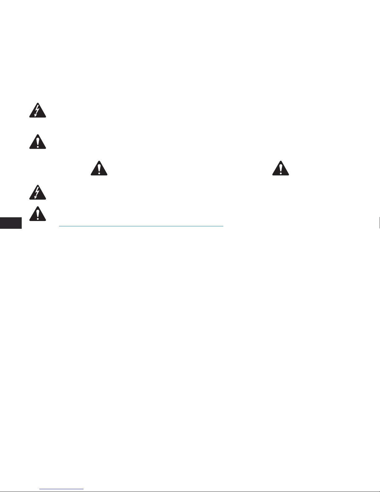
NOTE:
The intent of the lightning flash with arrowhead symbol in a triangle is to alert the user to the presence of un-insulated
"dangerous" voltage within the product's enclosure that may be of sufficient magnitude to constitute a risk of electric shock to humans.
NOTE:
The intent of the exclamation point within an equilateral triangle is to alert the user to the presence of important safety, and
operating and maintenance instructions in this manual.
IMPORTANT SAFETY INSTRUCTIONS
WARNING!:
TO PREVENT FIRE OR ELECTRIC SHOCK, DO NOT EXPOSE THIS EQUIPMENT TO RAIN OR MOISTURE.
WARNING!:
While it is possible for one person to lift a loudspeaker, it is important to use proper lifting techniques. Suggested
reading: OSHA Technical Manual on Back Disorders and Injuries
(http://www.osha.gov/dts/osta/otm/otm_vii/otm_vii_1.html#app_vii:1_2).
• Keep these instructions.
• Heed all warnings.
• Follow all instructions.
• Clean only with a dry cloth.
• Do not install near any heat sources such as radiators, heat registers, stoves, or other apparatus (including amplifiers) that produce heat.
• Only use attachments/accessories specified by the manufacturer.
• Refer all servicing to qualified service personnel.
• Adhere to all applicable, local codes.
• Consult a licensed, professional engineer when any doubt or questions arise regarding a physical equipment installation.
Introduction
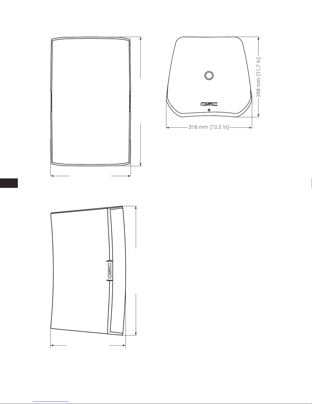
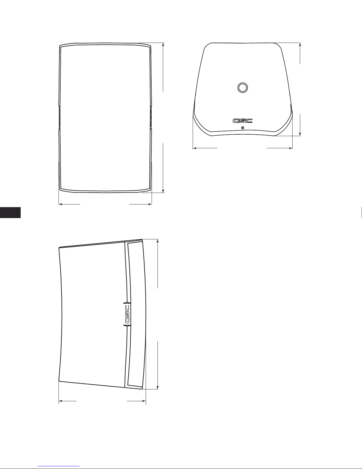
AcousticDesign series is a line of premium surface-mount loudspeakers intended for permanent installation applications. Housed in rugged ABS
molded enclosures, each loudspeaker (except the AD-S12 and AD-S112sw) features a 70/100V transformer for use with distributed-audio lines. The
unique X-Mount™ Bracket and Euro-style connector, supplied with each AcousticDesign loudspeaker, are designed for maximum flexibility and a quick
install. Featuring a knurled ball-mount and discrete angle deployment marks, installers can set loudspeaker deployment angles quickly and securely.
The Euro-style connector allows pre-wiring of the system and when combined with the quick “snap-on” deployment of the loudspeaker to the mount,
installation is completed in a fraction of the time required versus competitive models.
Unpacking
Package Contents
1. Quick-Start Guide
2. AcousticDesign Loudspeaker
3. Euro-style Connector, 4-pin
4. Terminal Weather Protection Cover
5. Phillips Screws (4) M4 (Terminal Weather Protection Cover)
6. X-Mount™ Bracket (Yoke Mount for AD-S112sw)

3
EN
TD-000329-00-C
Set the Transformer Tap Switch
Refer to — Figure 1
1. Insert a 4mm flat-tip screwdriver into Transformer Tap hole
and engage the slot.
2. At fully clockwise the transformer is in 8-bypass.
AD-S10T
AD-S6T, AD-S8T
Mount the Loudspeakers
Install the X-Mount™ Bracket
Refer to — Figure 4
WARNING!:
Install the system in accordance
with local building codes and regulations. Use
a licensed contractor or professional engineer.
QSC Audio Products is not responsible for
damages resulting from the negligent
installation of any bracket or loudspeaker.
1. Mount to a surface capable of supporting the weight of
the loudspeaker.
— Figure 1 —
4mm
100 Volt 70 Volt
8 Ω8 Ω
N/A 100W
100W 50W
50W 25W
25W 12.5W
— Table 1 —
— Figure 2 —
100 Volt 70 Volt
8 Ω8 Ω
N/A 60W
60W 30W
30W 15W
15W 7.5W
— Table 2 —
— Figure 3 —
— Figure 4 —

4
EN
TD-000329-00-C
Adjust the Angle of the X-Mount™ Bracket
Refer to — Figure 5
NOTE:
This step may be done now or after mounting the loudspeaker.
1. Use a 5mm hex wrench to loosen the adjustment locking screws.
2. Orient the bracket as necessary.
3. Tighten the adjustment locking screws.
— Figure 5 —
~
~ +/-70º
-15° +30°
+/-40º
5 mm
Not available
on AD-S6T
~
~ +/-60º (AD-S6T)
SIDE TOP FRONT

5
EN
TD-000329-00-C
Mount the Loudspeaker on the Bracket
Refer to — Figure 6.
NOTE:
The loudspeaker can be placed on the
mount in ANY direction (Up, Down, Left, Right).
1. Align the "X" slot with the X-Mount™ bracket and push the
loudspeaker onto the bracket. (1)
2. When seated, pull the loudspeaker down to lock the
loudspeaker onto the bracket. (2)
3. (Optional) Remove and retain the security tab (3); pull
straight out. To remove the loudspeaker, re-install the
security tab, press in and then remove the loudspeaker.
Connect a Safety Tether (Not supplied)
WARNING!:
DO NOT connect the tether to
the mounting bracket or the screws holding the
mounting bracket.
1. It is recommended that you connect a safety tether from the
safety ring (4) on the back of the loudspeaker to a spot on
the wall that is structurally sufficient to hold the weight of
the loudspeaker in the event the loudspeaker should fall.
Suspend the Loudspeaker
Refer to — Figure 7
WARNING!:
Suspend the loudspeaker in accordance with local building codes and
regulations. Use a licensed contractor or professional engineer. QSC Audio Products is not
responsible for damages resulting from the negligent installation of suspension cabling, or
loudspeaker.
The AcousticDesign loudspeakers (models AD-S8T, AD-S10T and AD-S12) may be suspended using the pull-
back point and M10 eyebolts you install at the bottom of the enclosures.
NOTE:
Suspending the enclosure woofer side up positions the HF closer to the listener
and helps improve bass response when coupled against the ceiling and wall planes.
1. Remove 2 M10 plugs (not shown) from the bottom of the loudspeaker enclosure.
2. Install two M10 -1.5 eyebolts (2) (accessory M10 Kit-C) in the M10 installation points on the bottom of the
loudspeaker enclosure.
3. Attach an appropriate cable to the tether Safety Ring (3) for the pull-back point.
Yoke-mount the Loudspeaker
In addition to the mounting methods listed above, you can mount the loudspeaker using the optional Yoke mounting kit Refer to instructions
provided in the Yoke kit. See the "Specifications" on page 12 for information.
— Figure 6 —
3
1
2
4
— Figure 7 —
2
3

6
EN
TD-000329-00-C
Install the Weather Cover (Optional)
Refer to — Figure 8
1. Slide the nut (1), compression gasket (2), and weather cover / gasket (3) over the
wiring for the loudspeaker.
2. Terminate the wiring to the Euro-style connector, refer to "Wire the Loudspeaker"
on page 6
3. Install the Euro-style connector.
4. Slide the weather cover/gasket (3) up next to the connection box, use a small
amount of wire, inside the cover, to provide strain relief.
5. Attach the weather cover to the enclosure with four screws (supplied).
6. Slide the compression gasket (2) into the weather cover receptacle.
7. Slide the nut over the weather cover receptacle and tighten.
Wire the Loudspeaker
Use up to 12 gage wiring as appropriate. Refer to — Figure 9.
1. If you are using the optional weather cover, make sure the wiring is inserted through all three parts of the weather cover in the proper order.
2. Install the negative and positive wires in the "Input" +/- as shown. Tighten the wire-clamp screws.
3. Install the daisy-chaining wires into the "Thru" +/- as shown. These wires go to the next loudspeaker in the daisy-chain.
Remove the Loudspeaker
1. Make sure all the wiring is disconnected, and the safety tether is removed.
2. If the security tab, located at the base of the loudspeaker mount, has NOT been removed, push the tab in and slide the loudspeaker in the
opposite direction of how it was installed.
3. If the security tab has been removed, re-insert it, or use a small rod (<4 mm / 0.16") to push in and release the mount lock.
— Figure 8 —
1
23
— Figure 9 —

7
EN
TD-000329-00-C
AD-S12 Dimensions
— Figure 10 —
596 mm (23.5 in)
354 mm (13.9 in)
354 mm (13.9 in)
322 mm (12.7 in)
322 mm (12.7 in)
596 mm (23.5 in)

8
EN
TD-000329-00-C
AD-S10T Dimensions
— Figure 11 —
318 mm (12.5 in)
298 mm (11.7 in)
318 mm (12.5 in)
516 mm (20.3 in)
298 mm (11.7 in)
516 mm (20.3 in)

9
EN
TD-000329-00-C
AD-S8T Dimensions
— Figure 12 —
254 mm (10 in)
251 mm (9.9 in)
251 mm (9.9 in)
440 mm (17.3 in)
254 mm (10 in)
440 mm (17.3 in)

10
EN
TD-000329-00-C
AD-S6T Dimensions
— Figure 13 —
215 mm (8.5 in)
215 mm (8.5 in)
215 mm (8.5 in)
365 mm (14.4 in)
215 mm (8.5 in)
365 mm (14.4 in)

11
EN
TD-000329-00-C
AD-S112sw Dimensions
— Figure 14 —
596 mm (23.5 in)
354 mm (13.9 in)
354 mm (13.9 in)
322 mm (12.7 in)
322 mm (12.7 in)
596 mm (23.5 in)

12
EN
TD-000329-00-C
Specifications
AD-S6T AD-S8T AD-S10T
Configuration 6" 2-way with transformer 8” 2-way with transformer 10” 2-way with transformer
Effective Frequency Range (-10 dB) 160 – 20 kHz 55 – 20 kHz 50 – 19 kHz
Rated Voltage / Power 235 Vrms / 150 W 40 Vrms / 200 W 45 Vrms / 250 W
Broad-band Sensitivity 3 89 dB SPL 90 dB SPL 92 dB SPL
Coverage Angle (-6 dB) 4 105° 105° 90°
Directivity Factor (Q) 5 7 10
Directivity Index 7 dB 9 dB 10 dB
Maximum SPL Continuous (1 m) 5110 dB 113 dB 116 dB
Maximum SPL Peak (1 m) 5116 dB 119 dB 122 dB
Nominal Impedance 888
Recommended Amplifier Power 300 W 400 W 500 W
Transformer Tap 70 V 60, 30, 15, 7.5 W and 8bypass 60, 30, 15, 7.5 W and 8bypass 100, 50, 25, 12.5 W and 8Bypass
Transformer Tap 100 V 60, 30, 15 W and 8bypass 60, 30, 15 W and 8bypass 100, 50, 25 W and 8Bypass
High-frequency Transducer 1” silk dome tweeter / 1” voice-coil horn loaded 1” Exit / 1.4” Voice-coil Compression Driver 1” Exit / 1.4” Voice-coil Compression Driver
Low-frequency Transducer 6” weather resistant paper cone woofer, 38 mm
/ 1.5” voice-coil
8” Weather Resistant Paper Cone Woofer, 50
mm / 2” Voice-coil
10” Weather Resistant Paper Cone Woofer, 64
mm / 2.5” Voice-coil
Input Connector Euro-style Connector with Parallel Output
Enclosure Details
Material ABS Polymer
Finish Black RAL 9011 or White RAL 9010 Paint
Grille Powder-coated Aluminum
X-Mount Material Powder-coated Aluminum
Ingress Protection Meets IP-54 for dust and splash resistance.
Operating Environment Designed for indoor and outdoor use
Operating Temperature Range -20 to 50 °C / -4 to 122 °F
Testing: Qualified for outdoor
use using the following tests:
Salt fog: MIL-STD-810G Method 509.5 for 100 hrs.
Humidity: MIL-STD-810G Method 507.5, Natural cycle B2, cyclic high RH for 7 days
High and low temperature: tested to QSC internal standards between -20° and 50° C
Weight (Net) 6.2 kg / 13.6 lbs 11 kg / 24 lbs 14 kg / 31 lbs
Dimensions (HWD) 365 mm x 215 mm x 215 mm
14.4" x 8.5" x 8.5"
440 mm x 254 mm x 251 mm
17.3" x 10.0" x 9.8"
516 mm x 318 mm x 298 mm
20.3" x 12.5" x 11.7"
Included Accessories X-Mount™ system, Euro-style connector, input
panel cover
X-Mount™ system, Euro-style connector X-Mount™ system, Euro-style connector
Optional Accessories N/A Yoke Mount Bracket Kit –
YMS8T-WHT / YMS8T-BLK
M10 Kit-C
Yoke Mount Bracket Kit –
YMS10T-WHT / YMS10T-BLK
M10 Kit-C
1 Free-field, -10 dB from on-axis sensitivity
2 IEC60268-1 noise signal for 2 Hrs
3 On-Axis, free-field sensitivity, 2.83V, 1 m
4 Coverage angle measured with 3 - 10 kHz bandwidth
5 Calculated from rated noise voltage and sensitivity

13
EN
TD-000329-00-C
Specifications
AD-S12 AD-S112sw
Configuration 12” 2-way 12” direct-radiating subwoofer
Effective Frequency Range (-10 dB) 152 – 20 kHz 30 – 135 Hz
Rated Voltage / Power 250 Vrms / 300 W 50 Vrms / 300 W
Broad-band Sensitivity 395 dB SPL 90 dB SPL
Coverage Angle (-6 dB) 475° M10 Kit-C
Directivity Factor (Q) 12 N/A
Directivity Index 11 dB N/A
Maximum SPL Continuous (1 m) 5120 dB 115 dB
Maximum SPL Peak (1 m) 5126 dB 121 dB
Nominal Impedance 88
Recommended Amplifier Power 600 W 600 W
Transformer Tap 70 V N/A N/A
Transformer Tap 100 V N/A N/A
High-Frequency Transducer 1” Exit / 1.4” Voice-coil Compression Driver N/A
Low-frequency Transducer 12” Weather Resistant Paper Cone Woofer, 64
mm / 2.5" Voice-coil
12” weather resistant paper cone woofer,
64 mm / 2.5” voice-coil
Input Connector Euro-style Connector with Parallel Output
Enclosure Details
Material ABS Polymer
Finish Black RAL 9011 or White RAL 9010 Paint Black RAL 9011 Paint
Grille Powder-coated Aluminum
Yoke Material Powder coated galvanized steel
Ingress Protection Meets IP-54 for dust and splash resistance.
Operating Environment Designed for indoor and outdoor use
Operating Temperature Range -20 to 50 °C / -4 to 122 °F
Testing: Qualified for outdoor
use using the following tests:
Salt fog: MIL-STD-810G Method 509.5 for 100 hrs.
Humidity: MIL-STD-810G Method 507.5, Natural cycle B2, cyclic high RH for 7 days
High and low temperature: tested to QSC internal standards between -20° and 50° C
Weight (Net) 16 kg / 35.0 lbs 13.2 kg / 29 lbs
Dimensions (HWD) 596 mm x 354 mm x 323 mm
23.5" x 13.9" x 12.7"
596 mm x 354 mm x 322 mm
23.5" x 13.9" x 12.7"
Included Accessories X-Mount™ system, Euro-style connector 596 mm x 354 mm x 323 mm
23.4" x 13.9" x 12.7"
Optional Accessories Yoke Mount Bracket Kit –
YMS12-WHT / YMS12-BLK
M10 Kit-C
M10 Kit-C
1 Free-field, -10 dB from on-axis sensitivity
2 IEC60268-1 noise signal for 2 Hrs
3 On-Axis, free-field sensitivity, 2.83V, 1 m
4 Coverage angle measured with 3 - 10 kHz bandwidth
5 Calculated from rated noise voltage and sensitivity

Mailing Address:
QSC Audio Products, LLC
1675 MacArthur Boulevard
Costa Mesa, CA 92626-1468 USA
Telephone Numbers:
Main Number: (714) 754-6175
Sales & Marketing: (714) 957-7100 or toll free (USA only) (800) 854-4079
Customer Service: (714) 957-7150 or toll free (USA only) (800) 772-2834
Facsimile Numbers:
Sales & Marketing FAX: (714) 754-6174
Customer Service FAX: (714) 754-6173
World Wide Web:
www.qsc.com
E-mail:
© 2013 QSC Audio Products, LLC. All rights reserved. QSC and the QSC logo are registered trademarks of QSC Audio Products, LLC in the U.S. and other countries. X-Mount is a
trademark of QSC Audio Products, LLC. All other trademarks are the property of their respective owners. U.S. and international patents pending.
http://patents.qsc.com

Serie AscousticDesign™
Guía del usuario
AD-S6T – altavoz principal/secundario bidireccional de 6" con transformador de 70/100 V
AD-S8T – altavoz principal/secundario bidireccional de 8" con transformador de 70/100 V
AD-S10T – altavoz principal/secundario bidireccional de 10" con transformador de 70/100 V
AD-S12 – altavoz principal/secundario bidireccional de 12"

2
ES
TD-000329-00-C
EXPLICACIÓN DE LOS SÍMBOLOS
El término “¡ADVERTENCIA!” indica instrucciones con respecto a la seguridad personal. Si no se siguen dichas instrucciones, se pueden ocasionar
lesiones corporales o la muerte.
El término “¡PRECAUCIÓN!” indica instrucciones con respecto a posibles daños al equipo físico. Si no se siguen dichas instrucciones, se pueden
ocasionar daños al equipo que pueden no estar cubiertos bajo la garantía.
El término “¡IMPORTANTE!” indica instrucciones o información que son vitales para completar satisfactoriamente el procedimiento.
El término “NOTA” se utiliza para indicar información adicional de utilidad.
NOTA:
La intención del símbolo de un rayo con punta de flecha dentro de un triángulo equilátero es alertar al usuario de la presencia
de voltaje “peligroso” no aislado dentro de la caja del producto, que puede ser de suficiente magnitud para constituir un riesgo de
descarga eléctrica a los seres humanos.
NOTA:
La intención del signo de exclamación dentro de un triángulo equilátero es alertar al usuario de la presencia de importantes
instrucciones de seguridad, operación y mantenimiento en este manual.
INSTRUCCIONES IMPORTANTES DE SEGURIDAD
¡ADVERTENCIA!:
PARA PREVENIR INCENDIOS O DESCARGAS ELÉCTRICAS, NO EXPONGA ESTE EQUIPO A LA LLUVIA NI A LA
HUMEDAD.
¡ADVERTENCIA!:
Si bien es posible que una persona levante un altavoz, es importante utilizar las técnicas apropiadas para levantarlo.
Se recomienda leer el manual técnico de la OSHA sobre trastornos y lesiones de la espalda
(http://www.osha.gov/dts/osta/otm/otm_vii/otm_vii_1.html#app_vii:1_2).
• Conserve estas instrucciones.
• Ponga atención a todas las advertencias.
• Siga todas las instrucciones.
• Límpielo solo con un paño seco.
• No lo instale cerca de fuentes de calor tales como radiadores, rejillas térmicas, estufas ni otros aparatos (inclusive amplificadores)
que produzcan calor.
• Use solo piezas/accesorios especificados por el fabricante.
• Refiera todo el servicio a personal calificado.
• Cumpla con todos los códigos locales aplicables.
• Consulte a un ingeniero profesional con la debida licencia cuando surjan dudas o preguntas referentes a la instalación física del equipo.
Introducción
La serie AcousticDesign es una línea de altavoces de montaje en superficie diseñada para aplicaciones con instalaciones permanentes. Alojado en
resistentes cajas moldeadas con ABS, cada altavoz (salvo el AD-S12) cuenta con un transformador de 70/100 V para utilizarse en líneas de sonido
distribuido. El soporte X-Mount™ y el conector de estilo europeo exclusivos, suministrados con cada altavoz AcousticDesign, están diseñados para
aportar una flexibilidad máxima y facilitar la instalación rápida. Con un montaje de bola moleteado y discretas marcas de colocación en ángulo,
los instaladores pueden disponer ángulos de colocación de los altavoces de forma rápida y segura. El conector de estilo europeo permite precablear
el sistema y, cuando se combina con la colocación de conexión a presión del altavoz al soporte, la instalación se completa en una fracción del tiempo
requerido por los modelos de la competencia.
Desembalaje
Contenido de la caja
1. Guía de inicio rápido
2. Altavoz AcousticDesign
3. Conector de estilo europeo, 4 patillas
4. Cubierta resistente a la intemperie
5. Tornillos Phillips (4) M4 (para la cubierta resistente a la intemperie)
6. Soporte X-Mount™

3
ES
TD-000329-00-C
Configure el conmutador de tomas del transformador
Consulte Figure 1.
1. Inserte un destornillador de punta plana de 4 mm en el
orificio de la toma del transformador y acóplelo a la ranura.
2. Girado totalmente a la derecha, el transformador está en
derivación de 8 .
AD-S10T
S8T
Monte los altavoces
Instale el soporte X-Mount™
Consulte Figure 4.
¡ADVERTENCIA!:
Instale el sistema de acuerdo
con los códigos y reglamentos locales de la
construcción. Utilice un contratista que cuente
con licencia o un ingeniero profesional.
QSC Audio Products no es responsable de los
daños derivados de la instalación negligente de
un soporte o altavoz.
1. Monte en una superficie que pueda soportar el peso
del altavoz.
— Figure 1 —
4mm
— Figure 2 —
100 V 70 V
8 Ω8 Ω
N/A 100 W
100 W 50 W
50 W 25 W
25 W 12,5 W
— Table 1 —
— Figure 3 —
100 V 70 V
8 Ω8 Ω
N/A 60 W
60 W 30 W
30 W 15 W
15 W 7,5 W
— Table 2 —
— Figure 4 —

4
ES
TD-000329-00-C
Ajuste el ángulo del soporte X-Mount™
Consulte Figure 5.
NOTE:
Este paso puede realizarse ahora o después de montar el altavoz.
1. Utilice una llave hexagonal de 5 mm para aflojar los tornillos de bloqueo de ajuste.
2. Oriente el soporte según sea necesario.
3. Apriete los tornillos de bloqueo de ajuste.
— Figure 5 —
CARA SUPERIOR
~
~ +/-70º
CARA LATERAL
-15° +30°
CARA DELANTERA
+/-40º
5 mm
~
~ +/-60º (AD-S6T)
No disponible
en AD-S6T

5
ES
TD-000329-00-C
Monte el altavoz en el soporte
Consulte Figure 6.
NOTA:
El altavoz puede colocarse en el
montaje en CUALQUIER dirección (hacia arriba,
hacia abajo, a la izquierda, a la derecha).
1. Alinee la ranura “X” con el soporte X-Mount™ y empuje el
altavoz en el soporte. (1)
2. Una vez asentado, baje el altavoz para fijarlo en el soporte. (2)
3. (Opcional) Retire la lengüeta de seguridad y consérvela
(3); extráigala recto hacia fuera. Para retirar el altavoz,
vuelva a colocar la lengüeta de seguridad, presione hacia
dentro y luego retire el altavoz.
Conecte una brida de seguridad
(no suministrada)
AVISO!:
NO conecte la brida al soporte de
montaje ni a los tornillos que sujetan el soporte
de montaje.
1. Se recomienda conectar una brida de seguridad desde el
anillo de seguridad (4) en la parte posterior del altavoz a un
punto en la pared que estructuralmente pueda soportar el
peso del altavoz en el caso de que este se caiga.
Cuelgue el altavoz
Consulte Figure 7.
AVISO!:
Cuelgue el altavoz de acuerdo con los códigos y reglamentos locales de la
construcción. Utilice un contratista que cuente con licencia o un ingeniero profesional. QSC
Audio Products no es responsable de los daños derivados de la instalación, suspensión o
cableado negligentes del altavoz.
Los altavoces AcousticDesign (modelos AD-S8T, AD-S10T y AD-S12) pueden colgarse usando el punto de
pretensado y los pernos de anilla M10 que se instalan en la base de las cajas.
NOTA:
Colgar la caja del woofer con la cara lateral hacia arriba hace que el HF quede más
cerca del oyente, y ayuda a mejorar la respuesta de los bajos cuando se acopla contra los
planos del techo y la pared.
1. Retire los dos tapones M10 (no se muestran) de la base de la caja del altavoz.
2. Instale dos (2) pernos de anilla M10-1,5 (kit M10 auxiliar-C) en los puntos de intalación M10 en la base
de la caja del altavoz.
3. Conecte un cable adecuado a la anilla de seguridad de la brida (3) para el punto de pretensado.
Instale el altavoz con el soporte de horquilla
Además de los métodos de montaje descritos anteriormente, puede instalar el altavoz con el kit de montaje en horquilla opcional. Consulte las
instrucciones suministradas con el kit de la horquilla. Consulte las “Especificaciones” en la página 12 para obtener más información.
— Figure 6 —
3
1
2
4
— Figure 7 —
2
3

6
ES
TD-000329-00-C
Instale la cubierta resistente a la intemperie (opcional)
Consulte Figure 8.
1. Deslice la tuerca (1), la junta de compresión (2) y la cubierta resistente a la
intemperie/junta (3) sobre el cable del altavoz.
2. Acabe el cable con un conector de estilo europeo, consulte “Conecte los cables del
altavoz” en la página 6
3. Instale el conector de estilo europeo.
4. Deslice la cubierta resistente a la intemperie/junta (3) hacia arriba hasta la caja de
conexiones, utilice un trozo pequeño de cable, dentro de la cubierta, para proporcionar
protección y alivio de tensión.
5. Sujete la cubierta resistente a la intemperie a la caja con cuatro tornillos
(suministrados).
6. Deslice la junta de compresión (2) al interior del receptáculo de la cubierta
resistente a la intemperie.
7. Deslice la tuerca sobre el receptáculo de la cubierta resistente a la intemperie
y apriétela.
Conecte los cables del altavoz
Utilice cables hasta de calibre 12 según sea pertinente. Consulte Figure 9.
1. Si está usando la cubierta resistente a la intemperie opcional, asegúrese de que los cables se inserten a través de las tres partes de dicha cubierta
en el orden correcto.
2. Instale los cables negativo y positivo en las tomas “Input” (entrada) +/-, tal como se muestra. Aprite los tornillos de las abrazaderas de cable.
3. Instale los cables de cadena en margarita en las tomas “Thru” (conexión directa) +/-, tal como se muestra. Estos cables van al siguiente altavoz
en la cadena en margarita.
Retire el altavoz
1. Asegúrese de que todos los cables estén desconectados y la brida de seguridad retirada.
2. Si la lengüeta de seguridad, localizada en la base del montaje del altavoz, NO se ha retirado, presione la lengüeta hacia dentro y deslice el altavoz
en la dirección opuesta a la que lo instaló.
3. Si la lengüeta de seguridad se ha retirado, vuelva a insertarla o utilice una varilla pequeña (<4 mm/0,16 pulgadas)
para presionar hacia dentro
y soltar el bloqueo del montaje.
— Figure 8 —
1
23
— Figure 9 —
This manual suits for next models
4
Table of contents
Languages:
Other QSC Speakers System manuals