QSC MHV-1090 User manual

*TD-000246-00*
Cinema Mid-High-Very High Loudspeaker System User Manual
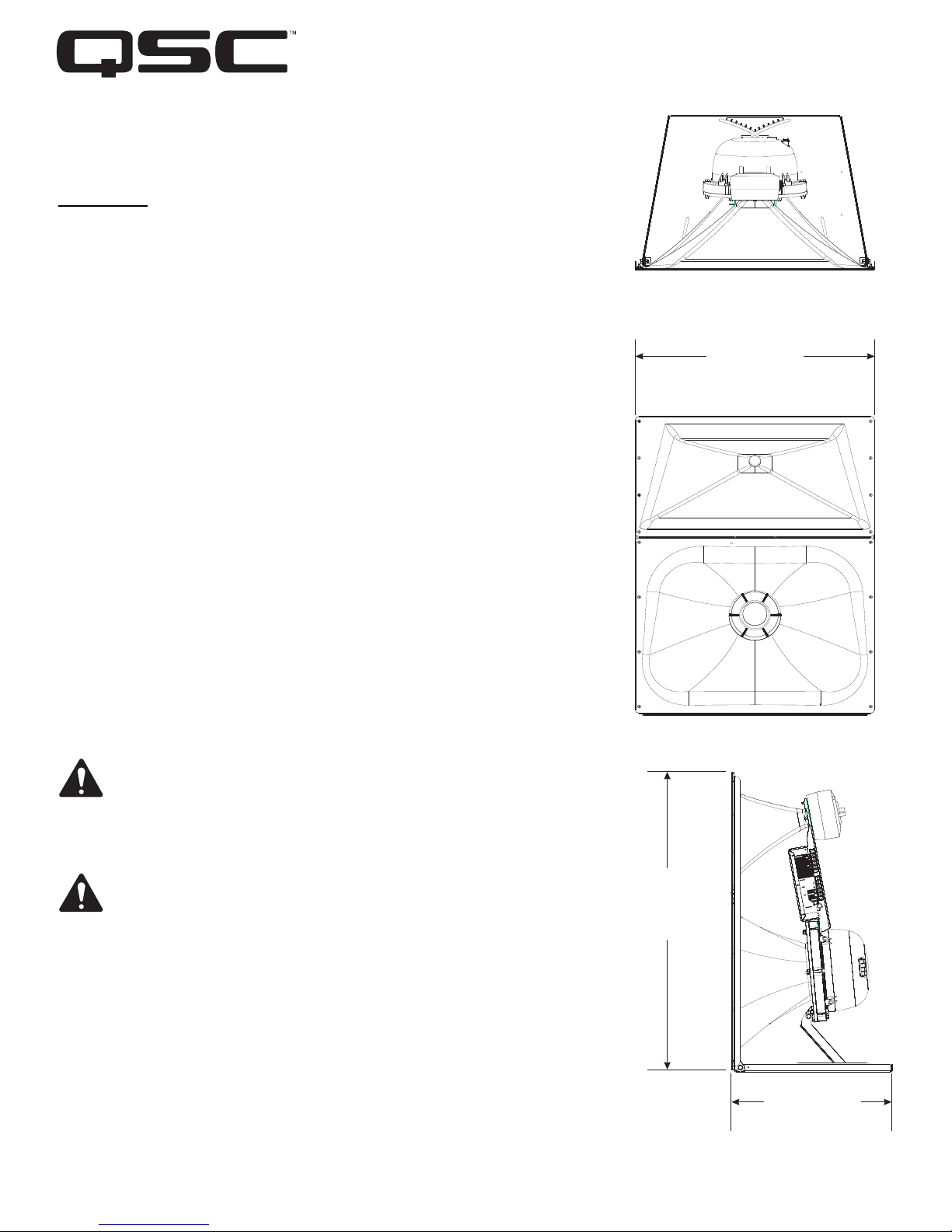
MHV-109010” (254mm) mid, coax high- very high compression driver
Introduction
The MHV-1090 system provides the mid, high, and very high-frequency components
offour-wayscreenchannel loudspeaker system for high performance cinema applica-
tions. It was designed to operate with and be directly mounted on QSC’s cinema low-
frequency enclosures.
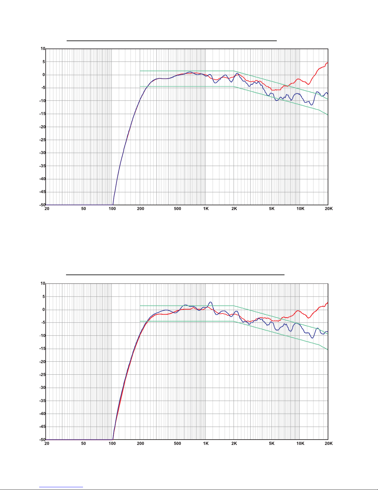
The high-frequency horn is a low-distortion waveguide providing highly articulate dia-
logue without the coloration associated with conventional horn loudspeakers. Both
horns feature broad horizontal and vertical coverage to ensure audio integrity is deliv-
ered to every seat in the auditorium. The driver assembliesare mountedon an adjust-
able pan and tilt bracket that has an integral aiming sight, simplifying installation.
The MHV-1090 includes a driver protection and high-very high-frequency crossover
network to assure reliable operation. DC blocking capacitors protect against DC or
low-frequency signals that could damage an unprotected driver. A 12 dB per octave
crossover seamlessly blends the high and very high-frequency elements when oper-
ated in tri-amp mode. Outboard processing is requiredtoformthecrossoverbetween
the low, mid, and high-very high-frequency drivers.
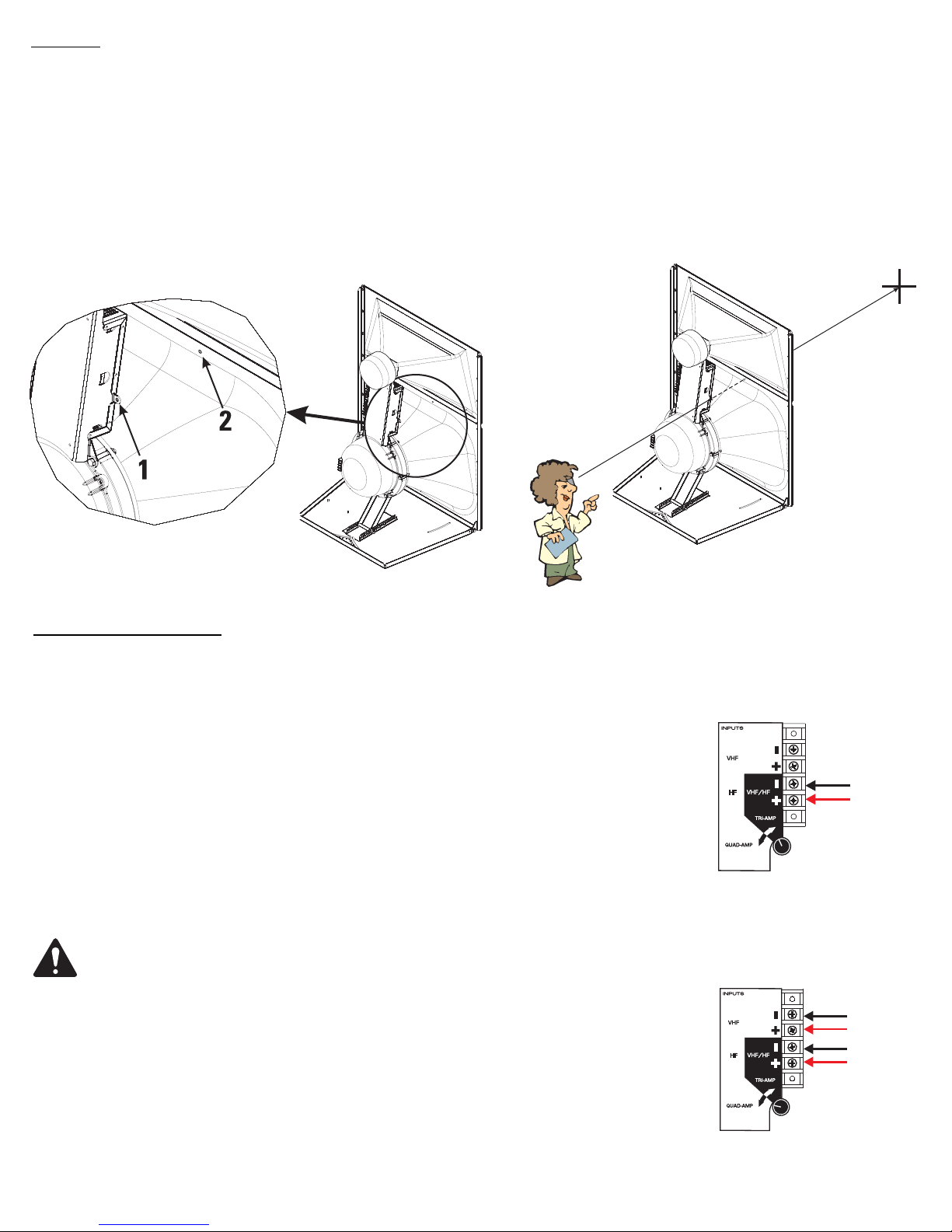
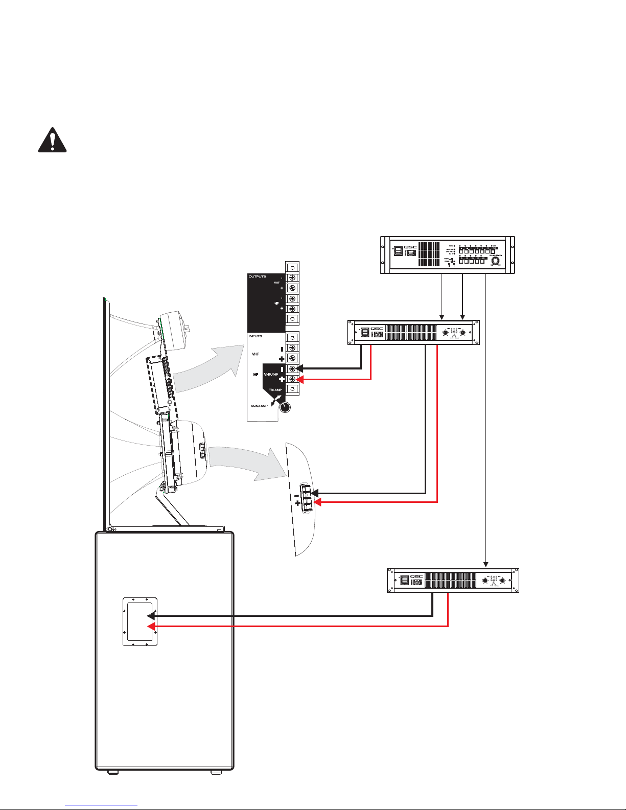
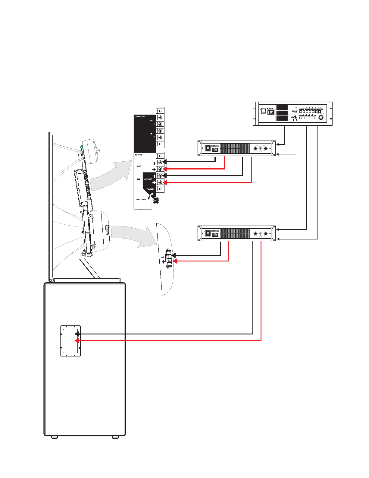
Tri-amp or quad-amp operation is possible using a selector switch mounted on the
INPUTS connection panel. The tri-amp setting provides a built-in passive crossover
network between high and very high-frequency drivers. Separate amplifiers and
active crossovers are required for the low, mid, high-very high-frequency channels.
Quad-amp setting disables the internal high-very high-frequency crossover and each
driver is driven independently by its own amplifier and active crossover; one each
required for the low, mid, high, and very high-frequency drivers.
The MHV-1090 components come pre-assembled to reduce field assembly time.
Three bolts are all that are required to secure the assembly to the top of a QSC low-
frequency enclosure.
Install in accordance with QSC Audio Product’s instructions and a
licensed, professional engineer. Only use attachments, mounts, acces-
sories, or brackets specified by QSC Audio Products, LLC Refer all ser-
vicing to qualified personnel. Servicing is required when the apparatus
has been damaged in any way.
WARNING! Before placing, installing, rigging, or suspending any
speaker product, inspect all hardware, suspension, enclosures, trans-
ducers, brackets and associated equipment for damage. Any missing,
corroded, deformed or non-load rated component could significantly
reduce the strength of the installation, placement, or array. Any such
condition severely reduces the safety of the installation and should be
immediately corrected. Use only hardware which is rated for the loading
conditions of the installation and any possible short-term unexpected
overloading. Never exceed the rating of the hardware or equipment.
Consult a licensed, professional engineer when any doubt or questions
arise regarding a physical equipment installation.
TD-000246-00-B
© Copyright 2007, QSC Audio Products, LLC
QSC® is a registered trademark of QSC Audio Products, LLC
“QSC” and the QSC logo are registered with the U.S. Patent and Trademark Office
1675 MacArthur Blvd., Costa Mesa, CA, 92626 USA
Main Number (714) 754-6175
Sales & Marketing (714) 957-7100 or toll free (USA only) (800) 854-4079
Customer Service(714) 957-7150 or toll free (USA only) (800) 772-2834
30”
(762mm)
39”
(991mm)
20”
(508mm)

Settings and Connections
TRI-AMP / QUAD-AMP Operating Mode Selection
Settheoperatingmode selectorswitchtoTRI-AMP orQUAD-AMP,dependingonyour screenchannel
signal processing and amplification set-up. The mid-frequency driver will require connection to its rear
cover terminals, regardless of mode selection. The low-frequency driver will also require its own, sepa-
rate connections. The only connection difference between tri-amp and quad-ampmodes is in quad-
amp mode, the very high-frequency signal will require connection to the terminals labeled VHF.
TRI-AMP-When set to TRI-AMP, the MHV-1090 input panel connections accept high-frequency/very
high-frequency signals on one set of inputs and uses an internal crossover network between the high
and very high-frequency drivers.
QUAD-AMP- When set to QUAD-AMP, the MHV-1090 input panel accepts separate high and very
high-frequency signals on two separatesets of inputs. The internal crossovernetwork is bypassed and
only the protective circuitry for the high-frequency and very high-frequency driver remains. Each of the
driver’s signals must have the appropriate upstream signal processing.
•Do not connect amplifiers directly to the high/very high-frequency coaxial driver
inputs!
• Always use the crossover INPUTS terminal strip for high and very high-frequency
input(s)
•The mid-frequency driver and the low-frequency enclosure are connected directly
to their own separate amplifiers regardless of mode selector switch setting.
Mounting
Attaching to Low-frequency Enclosure
The MHV-1090 attaches to the top of QSC low-frequency enclosures with three M8 hex head bolts, 20mm minimum length. Use lock washers on all bolts.
The bolts and washers ship installed on the low-frequency enclosure. We recommend the use of serviceable thread locking compound when installing the
bolts to prevent loosening due to vibration. Do not fully tighten the mounting hardware before aiming in the horizontal plane (see below).
Aiming
Aim the horn in the horizontal plane (pan) before tightening the three bolts securing the MHV-1090 to the low-frequency enclosure. Adjust the vertical tilt
with the vertical adjustment bracket. The mid-high assembly is equipped with an aiming sight to assist in achieving desired coverage quickly and easily.
For typical applications, the aim point should be the center seat in the back row of the auditorium. If the cinema screen has already been installed, a flash-
light placed at the desired aiming point can be seen through the screen perforations in a darkened auditorium.
Where the sight holes are located: How to use the sights:
Aim point:
HF/VHF
VHF
HF
Mode selector switch set to
TRI-AMP and the required
HF/VHF connection:
Mode selector switch set to
QUAD-AMP and the required sep-
arate HF and VHF connections:

INPUTS Terminals
The MHV-1090 has barrier strip screw terminals that accept up to #10 AWG (5.3mm2) stranded loudspeaker wire. Observe proper polarity. Use the
largest wire size and shortest wire length for the application.
OUTPUTS Terminals
The OUTPUT terminals are factory-connected to the high and very high-frequency drivers. These terminals should ONLY be connected to their
respectivedriver.Donotconnect signals to these terminals as all protectionandequalizationcircuitrywill be bypassed.They arenotfordaisychaining
the signals to other drivers.
NOTE! Maintain proper loudspeaker connection polarity throughout the entire system for maximum performance. Do not apply full
range signal to the MHV-1090! There is a high/very high-frequency passive crossover for tri-amp mode only. There is no crossover
connected when operating in quad-amp mode. All required signal processing must be done before the signal is applied to the loud-
speaker. Do not connect any signal to the upper sets of OUTPUT terminals.
TRI-AMP mode connections- Ensure the mode selector switch is set to TRI-AMP, connect the low-frequency signal to the low-frequency enclosure;
connectthe mid-frequency signal to the mid-frequency driver; connect the high/very high-frequency signal to the VHF/HF terminals on the INPUTS ter-
minal strip.
LF
MF
HF/VHF
HF/VHF MF LF
Signal Processing
Amplification
Amplification
Low-frequency Enclosure
MHV-1090

QUAD-AMP mode connections- Ensure the mode selector switch is set to QUAD-AMP, connect the low-frequency signal to the low-
frequency enclosure; connect the mid-frequency signal to the mid-frequency driver; connect the high-frequency signal to the HF termi-
nals on the INPUTS terminal strip; connect the very high-frequency signal to the VHF terminals on the INPUTS terminal strip.
LF
MF
VHF MF LF
Signal Processing
Amplification
Low-frequency Enclosure
MHV-1090 HF
Amplification
VHF
HF

MHV-1090 Specifications (subject to change without notice)
Freq. Range 180 - 20k Hz (-6dB, full space)
Nominal Coverage 90°horizontal X +20 to -30° vertical (50° total, adjustable mount provides for vertical plane adjustments. The horizontal
plane can be adjusted by altering mounting position on the low-frequency enclosure before tightening bolts.
DI: 9 dB (400 to 16k Hz average)
Q: 8 (400 to 16k Hz average)
Max. Output:, calculated Mid-frequency 135.5 dB SPL
(1 meter, full space) Tri-amp mode: high-frequency/very high-frequency 138 dB SPL
Quad-amp mode: high-frequency 138 dB SPL, very high-frequency 135 dB SPL
Impedance: Tri-amp mode: 8 ohms nominal, mid-, high-, and very high-frequency
Quad-amp mode: 8 ohms nominal, mid-, high-, and very high-frequency
Maximum Input Power Mid-frequency: 275 W
(AES method, 2 hours) Tri-amp mode: high/very high-frequency 155 W (calculated, sum of high and very high-frequency individual ratings)
Quad-amp mode: high-frequency 85 W, very high-frequency 70 W
Sensitivity Mid-frequency: 105 dB SPL
(1 Watt, 1 meter) Tri-amp mode: high/very high-frequency 110 dB SPL
Quad-amp mode: high-frequency 110 dB SPL, very high-frequency 110 dB SPL
Crossover Frequencies Tri-amp mode: mid-frequency 250 Hz or higher, high-frequency/very-frequency 1.7 kHz, both 24 dB/octave
Quad-amp mode: mid-frequency 250 Hz or higher, high-frequency 1.7 kHz, very high-frequency 6.0 kHz, all 24 dB/
octave
Crossover Network High-frequency to very high-frequency crossover at 7 kHz, 12 dB per octave, only in tri-amp mode. Quad-amp mode
switch setting removes crossover circuit from signal path, but leaves DC blocking capacitors in circuit.
Connectors Mid-frequency driver: barrier strip screw terminals accept up to #10 AWG stranded wire
High-frequency, very high-frequency drivers: barrier strip screw terminals accept up to #10 AWG stranded wire
Tri-amp mode connect high-frequency/very high-frequency program only to VHF/HF INPUTS terminals
Quad-amp mode connect high-frequency program to HF INPUTS terminals and connect very high-frequency program
to VHF INPUTS terminals.
Transducers Mid-frequency: 10" high efficiency mid-range, phase-ring loaded
High-frequency: 1.5" exit, 3.5" voice coil polyester diaphragm coaxial compression driver
Very High-frequency: 1.5" exit, 1.75" voice coil polyester diaphragm coaxial compression driver
Mounting Hardware: Attaches to top of QSC’s low-frequency cinema enclosures using three M8 bolts, hex head, 20mm minimum length
(supplied with low-frequency enclosure)
Size 39” high x 30” wide x 20” deep (991 x 762 x 508mm)
Weight 73.5 lb. (33 kg) net

MHV-1090 SPL vs. Frequency, Tri-amp, No Screen
SPL (dB, normalized)
Frequency (Hz)
high/very high
mid
SPL (dB, normalized)
Frequency (Hz)
MHV-1090 SPL vs. Frequency, Quad-amp, No Screen
high
mid
very high

MHV-1090 SPL vs. Frequency, X-curve, Tri-amp, With and Without Screen
SPL (dB, normalized)
without screen
with screen
SPL (dB, normalized)
MHV-1090 SPL vs. Frequency, X-curve, Quad-amp, With and Without Screen
Frequency (Hz)
Frequency (Hz)
X-curve
X-curve -
without screen
with screen
X-curve
X-curve -

Warranty (USA only; other countries, see your dealer or distributor)
Disclaimer
QSC Audio Products, LLC is not liable for any damage to amplifiers, or any other equipment that is caused by negligence or
improper installation and/or use of this loudspeaker product.
QSC Audio Products 3 Year Limited Warranty
QSC Audio Products, LLC (“QSC”) guarantees its products to be free from defective material and / or workmanship for a
period of three (3) years from date of sale, and will replace defective parts and repair malfunctioning products under this war-
ranty when the defect occurs under normal installation and use - provided the unit is returned to our factory or one of our
authorized service stations via pre-paid transportation with a copy of proof of purchase (i.e., sales receipt). This warranty pro-
vides that the examination of the return product must indicate, in our judgment, a manufacturing defect. This warranty does
not extend to any product which has been subjected to misuse, neglect, accident, improper installation, or where the date
codehas been removed or defaced. QSC shall not be liable for incidentaland/orconsequentialdamages. This warrantygives
you specific legal rights. This limited warranty is freely transferable during the term of the warranty period.
Customer may have additional rights, which vary from state to state.
In the event that this product was manufactured for export and sale outside of the United States or its territories, then this lim-
ited warranty shall not apply. Removal of the serial number on this product, or purchase of this product from an unauthorized
dealer, will void this limited warranty. Periodically, this warranty is updated. To obtain the most recent version of QSC’s war-
ranty statement, please visit www.qscaudio.com. Contact us at 800-854-4079 or visit our website at www.qscaudio.com.
Contacting QSC Audio Products
Mailing address: QSC Audio Products, LLC
1675 MacArthur Boulevard
Costa Mesa, CA 92626-1468 USA
Telephone Numbers:
Main Number (714) 754-6175
Sales & Marketing (714) 957-7100 or toll free (USA only) (800) 854-4079
Customer Service (714) 957-7150 or toll free (USA only) (800) 772-2834
Facsimile Numbers:
Sales & Marketing Fax (714) 754-6174
Customer Service Fax (714) 754-6173
World Wide Web: www.qscaudio.com
E-mail: [email protected]
QSC Audio Products, LLC 1675 MacArthur Boulevard Costa Mesa, California 92626 USA
©2007 “QSC” and the QSC logo are registered with the U.S. Patent and Trademark Office.
Other manuals for MHV-1090
1
Table of contents
Other QSC Speakers System manuals