8
Ch. 2
Ch. 1
UF-2
EX4000
(stereo mode)
Ch. 2
Ch. 1
UF-2
EX2500
(parallel mode)
Ch. 2
Ch. 1
UF-2
EX4000
(bridged mode)
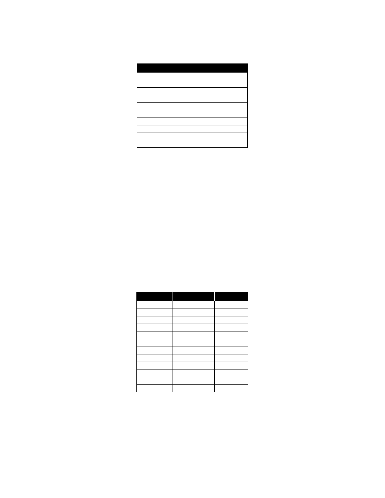
Ch. 1:
Ch. 2 LP @ 150 Hz; HP @ 20 Hz
Bypassed
UF-2: Subwoofer
Ch. 1:
Ch. 2 LP @ 1000 Hz; HP @ 150 Hz
LP @ 1000 Hz; HP @ 150 Hz
UF-2: Woofers
Ch. 1:
Ch. 2 LP @ 5 kHz; HP @ 1000 Hz
LP @ 20 kHz; HP @ 5 kHz
UF-2: Mids & Highs
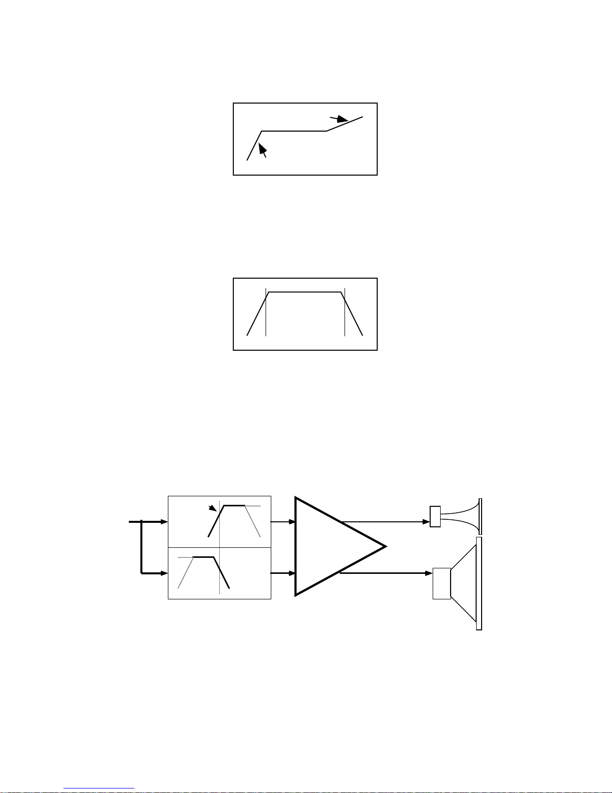
Subwoofer
Thesubwoofersubsystemin the example is driven
byabridgedamplifier.Channel1oftheUF-2inthis
amplifierissetwiththehigh-passfilter at 20 Hz (for
subsonic filtering) and the low-pass at 150 Hz,
which is the crossover point to the woofers. Chan-
nel 2 of the UF-2 is bypassed.
Woofer
Thewoofersaredrivenbyanamplifier operating in
theparallelmode.BothchannelsofitsUF-2areset
with the high-pass filter at 150 Hz (the crossover
pointfromthesubwoofers)andthelow-passfilterat
1 kHz.
Midrange and High Frequencies
The remaining speakers are driven by the same
amplifier: the mids by channel 1, and the highs by
channel 2. The settings for channel 1 of the UF-2
are: high-pass at 1 kHz (the crossover from the
woofers) and low-pass at 5 kHz (the crossover
point to the high-frequency drivers).
Channel2ofthe UF-2 issetforhigh-passat 5 kHz.
For ultrasonic protection, the low-pass is set at 20
kHz.
Figure 9—Multiple amplifiers with UF-2s,
set up for 4-way crossover operation
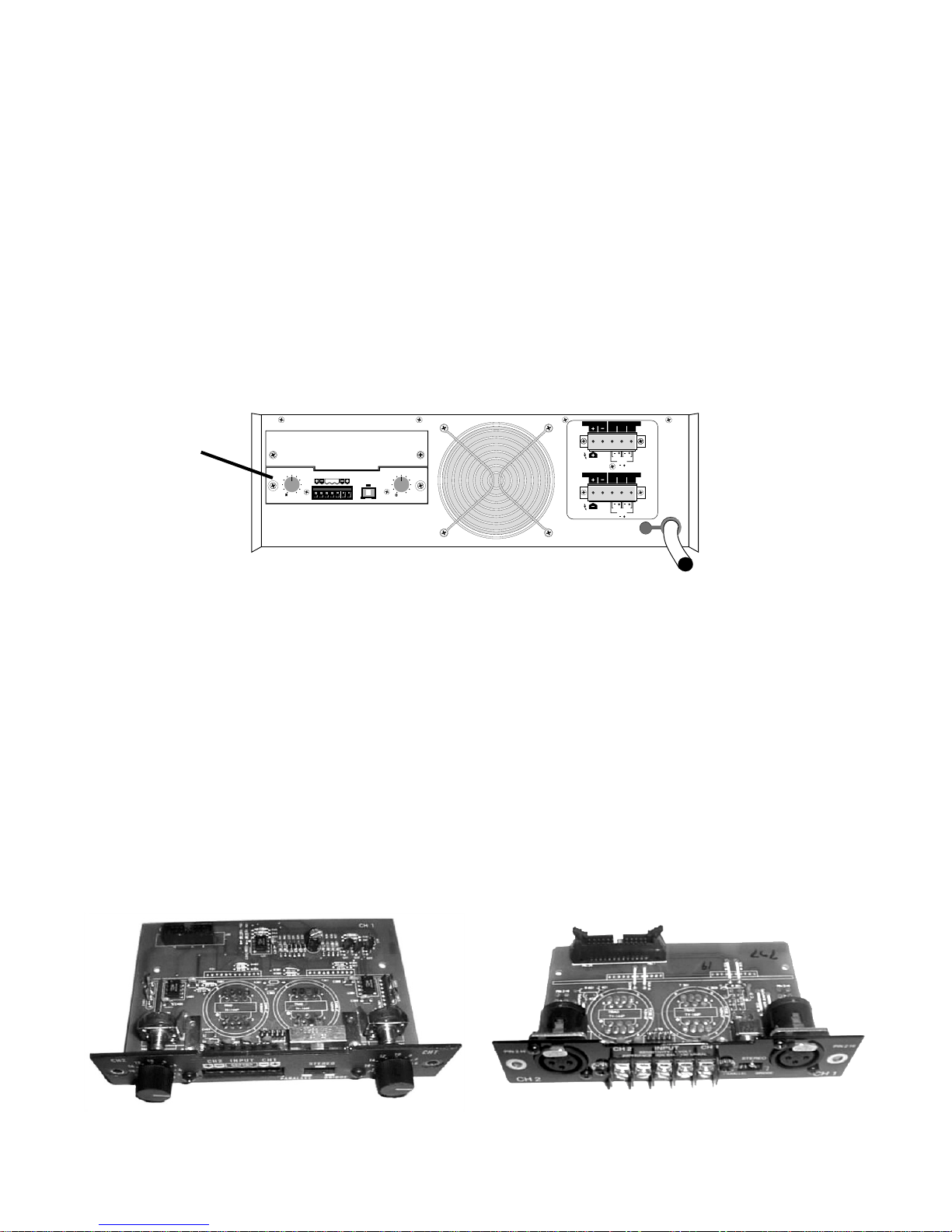
V. INSTALLATION
InstallingtheUF-2requiresPCboardsolderingskills,soonlyqualifiedservicetechniciansshouldattempt
it. Any authorized QSC service center—or, for an additional installation fee, the QSC factory service
center—can perform the installation.
TheUF-2installsontheamplifierinputPCboardofanyQSCEXSeriesamplifier.SomeolderEXamplifiers
may require an upgrade to the current input board. Contact the QSC Service Department for details on
compatibility with older EX amplifiers.
Wheninstalled,theUF-2settingsandadjustmentsarenotexternallyadjustable;thiscanpreventtampering
by unauthorized users.
Tools and materials you will need:
Soldering iron
Desoldering iron or other suitable desoldering equipment
Phillips screwdriver
Wire cutters
Rosin-core solder
Do not use desoldering braid because it may damage the Mini-Slot socket solder pads on the input board,
and it also might not adequately remove solder.