QTS AN-X4-ABRIO-HMI User manual

AN-X4-ABRIO-HMI User Manual

Page 2AN-X4-ABRIO-HMI Feb 2023
Because of the variety of uses for the products described in this publication, those responsible for the
application and use of these products must satisfy themselves that all necessary steps have been taken
to assure that each application and use meets all performance and safety requirements, including any
applicable laws, regulations, codes and standards. In no event will Quest Technical Solutions be
responsible or liable for indirect or consequential damage resulting from the use or application of
these products.
Any illustrations, charts, sample programs, and layout examples shown in this publication are
intended solely for purposes of example. Since there are many variables and requirements associated
with any particular installation, Quest Technical Solutions does not assume responsibility or liability
(to include intellectual property liability) for actual use based upon the examples shown in this
publication.
Throughout this manual we use notes to make you aware of safety considerations.
WARNING!
Identifies information about practices or circumstances that can lead to
personal injury or death, property damage, or economic loss.
These warnings help to:
•identify a hazard
•avoid the hazard
•recognize the consequences
IMPORTANT! Identifies information that is especially important for successful
application and understanding of the product.
TIP Identifies information that explains the best way to use the
AN-X4-ABRIO-HMI
Microsoft is a registered trademark of Microsoft Corporation.
Windows is a trademark of Microsoft Corporation.
ControlLogix, RSLinx and RSLogix 5000 are trademarks of the Allen-Bradley Company, Inc.

AN-X4-AB-DHRIO FOR REMOTE I/O HMI 6
Hardware Features 7
Package Contents 8
Using the MicroSD Card 8
Comparison with the AN-X2 9
RIO-HMI 9
General 9
INSTALLATION 10
Prevent Electrostatic Discharge 10
Power 10
Remote I/O Cabling and Termination 10
Ethernet Cabling 11
Hazardous Location Considerations 11
CONFIGURATION 12
Initial Ethernet Configuration 12
DHCP 13
Static IP Address 13
Factory Default Setting 13
Hostname 13
Submitting the Configuration 14
Reconfiguring an AN-X from an Unknown State 14
The Configuration File IPCfg\IPConfig.txt 14
Firmware to Run 15
REMOTE I/O CONFIGURATION 16
Configuring a Remote I/O Network 16
Configuration File 16
Baud Rate 16
Racks 16

Page 4AN-X4-ABRIO-HMI Feb 2023
Block Transfers 17
Sample Configuration 18
Block Transfers by Length 18
Sample Block Transfer by Length Configuration 18
LED Control Options 19
Other Options 19
Sending the Configuration to the AN-X 19
Sample Configuration File 20
ACCESSING DATA 21
USING THE WEB INTERFACE 27
Automation Network 27
Remote I/O HMI Configuration 27
Configuration View 28
RIO Discrete Data 30
RIO Block Transfers 32
RIO Diagnostics 34
Log Files 38
RIO-HMI Log 38
System Info Log 38
View All Logs 38
Administration Menu 39
AN-X IP Configuration 39
AN-X Firmware Select 40
AN-X Firmware Upload 40
AN-X Firmware Remove 40
AN-X Diagnostic Capture 40
AN-X Kernel Page 41
AN-X Kernel Update 42
AN-X Module REBOOT 42
Support Menu 42
Contact Information 42
TROUBLESHOOTING 43
LEDs 43
Ethernet LEDs 43
MS and NS LEDs 43

UPDATING THE FIRMWARE 45
SPECIFICATIONS 46
SUPPORT 47
WARRANTY 48

AN-X4-AB-DHRIO for Remote I/O HMI
The AN-X4-ABRIO-HMI communications module is used to connect HMI, SCADA, or MES
systems to data on an Allen-Bradley Remote I/O network. Typical applications include replacing
obsolete HMIs that have built-in Remote I/O cards with newer HMI terminals that connect to an
EtherNet/IP network such as a Panelview.
For applications where multiple HMI terminals exist on a single Remote I/O network, a single AN-X
gateway can be used to provide data to these HMI terminals.
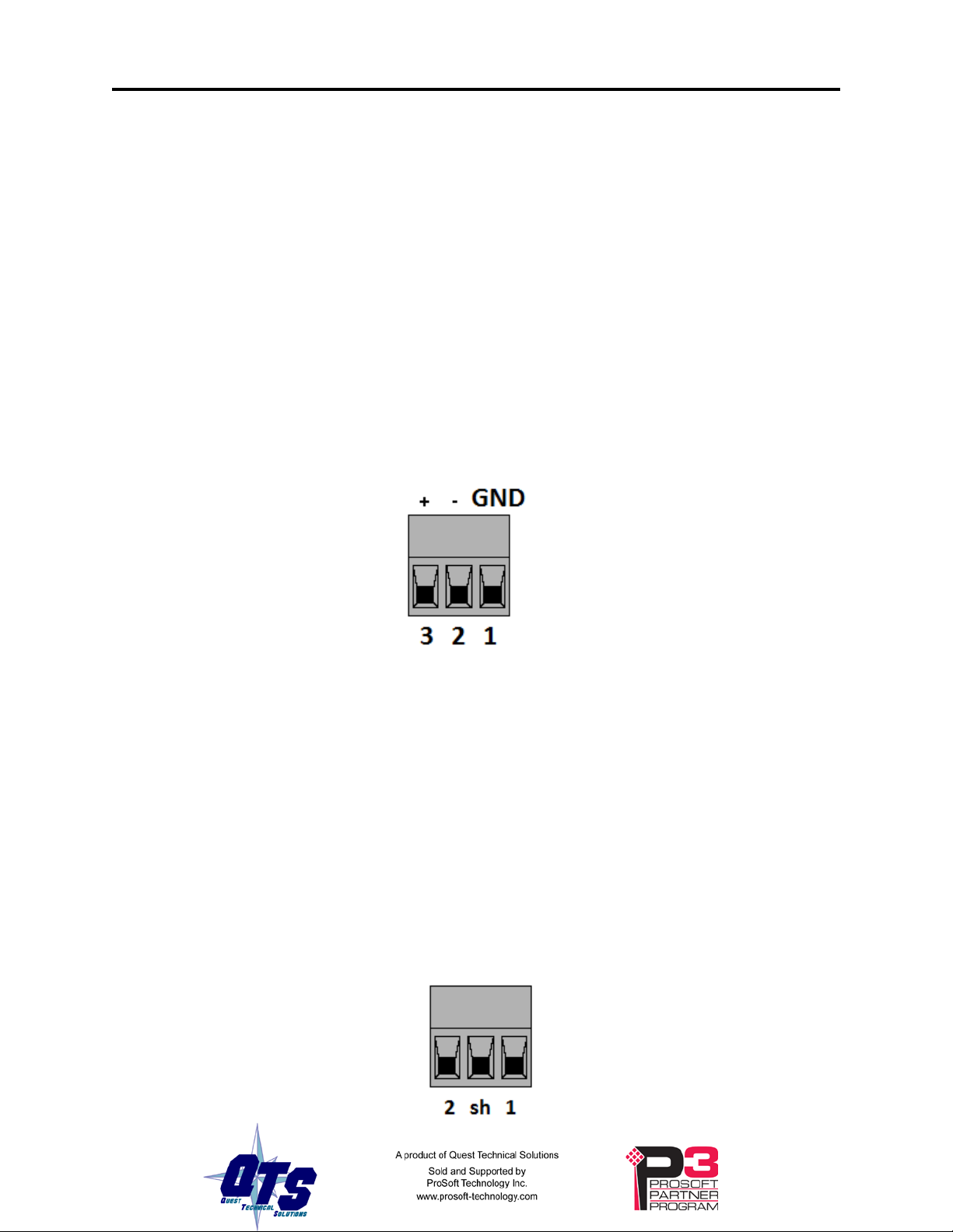
Remote I/O network features include:
•emulates up to 63 racks, with rack numbers from 0 to 76 octal, in any combination of
partial racks
•monitors other racks on the remote I/O network
•supports all remote I/O baud rates
•supports block transfer reads and writes at all possible locations on these racks
Ethernet IP devices access data on the AN-X as PLC-5 input (I), output (O), status (S), integer (N),
binary (B) and floating point (F) files.
The AN-X4-ABRIO-HMI module has a web interface for configuration, for monitoring data, logs and
diagnostic counters, and for performing other administrative functions. You can communicate with
the module using any standard web browser.
The module firmware can be updated over Ethernet using the web interface. Refer to page 40 for
details.
A jabber inhibit timer is implemented in the module’s hardware. If the network transmitter is on
longer than 150% of the longest network frame time, the transmitter is forced off and the module is
placed into a safe fatal failure state.
You can obtain the latest firmware from qtsusa.com/dist/AN-X4_Dist/ along with some quick start
instructions.

AN-X4-ABRIO-HMI Page 7
Hardware Features
The module has:
•LEDs to indicate the status of the connection to the Ethernet, its own internal state (MS), and
the state of the connection to the remote I/O network (NS)
•an Ethernet connector
•a 3-pin Phoenix connector to connect to the remote I/O network
•a 3-pin Phoenix power connector
•a microSD card for storage of configuration data and firmware
The pinouts on the power and the remote I/O connectors match those on the AN-X2. Cables for
the AN-X2 can be connected to the AN-X4 without change, though they are rotated 180 degrees.

Page 8AN-X4-ABRIO-HMI Feb 2023
Package Contents
•AN-X4-ABRIO module
•Phoenix power and network connectors
•microSD card
Using the MicroSD Card
The AN-X4 microSD card stores configuration data and firmware.
There are no restrictions on the size or speed of the card.
The microSD card must be present while the AN-X4 is running.
WARNING! Do not remove the microSD card while the AN-X4 is powered on!
There are several configuration files on the SD card.
Function File
Ethernet configuration IPCfg\IPConfig.txt
Remote I/O Configuration RioHmi\AnxAbRioHmiCfg.txt
Firmware to run Firmware\FirmwareCfg.txt
All files should be created and edited with a plain text editor such as Windows Notepad.
If the AN-X4 is inaccessible from Ethernet because of its settings, or is in an unknown state, you can
power down the AN-X4, remove the microSD card and edit the file IPConfig.txt. Refer to page 14
for details.
When you have finished editing the file, reinsert the card in the slot at the back of the AN-X4 and
restart the AN-X4.
WARNING! If you remove the card to edit the configuration file, push the card in straight
or the card might fall inside the case and you will have to disassemble the
AN-X4 to retrieve it .

AN-X4-ABRIO-HMI Page 9
Comparison with the AN-X2
If you are familiar with the AN-X2, or are replacing an AN-X2 with an AN-X4, you should be aware
of the following:
RIO-HMI
•The power and remote I/O cables are the same, but need to be rotated 180 degrees.
•The RIO-HMI configuration files are slightly changed and are saved at different
locations on the microSD card
•The web interface is improved, now has data displays for discrete and block transfer data
•The remote I/O capabilities are greatly improved
•Block transfer by length can now be defined at any location. There can now be up to 64
possible block transfer read lengths and 64 possible block transfer write lengths
•AN-X4 allows you to specify all other block transfer locations, as well as the block
transfer by length location.
•AN-X supports monitored racks on the same remote network, including discrete and
block transfer data. AN-X4 does not require an active rack definition, it can be monitor
only
•The status file information has been expanded
General
•The status and errors displayed on the LEDs have changed
•You can select a different version of the same firmware, e.g., remote I/O HMI firmware,
for testing and debugging
•As shipped, the AN-X searches for a DHCP IP address at startup for 10 seconds, then
reverts to static IP address 192.168.0.246
•The case is smaller

Page 10 AN-X4-ABRIO-HMI Feb 2023
Installation
Prevent Electrostatic Discharge
The module is sensitive to electrostatic discharge.
WARNING!
Electrostatic discharge can damage integrated circuits and
semiconductors. Follow these guidelines when you handle the module:
•Touch a grounded object to discharge static potential
•Do not touch the connector pins
Power
AN-X requires DC power input of anywhere from 12 to 24 VDC
The pins on the power connector are chassis ground, negative voltage and positive voltage. Pin 1 is
closest to the Ethernet connector.
Power consumption is 240 mA @ 12VDC or 120 mA @ 24VDC.
The part number for the power connector is Phoenix MSTB 2.5/3-ST-5.08 (1757022)
The power connector is the same as the AN-X2 but is rotated 180 degrees.
Remote I/O Cabling and Termination
Follow Allen-Bradley cabling recommendations for remote I/O. Refer to Approved Vendor List for
DH, DH+, DH-485, and Remote I/O Cables, publication ICCG-2.2, February 1996.
The network cable must be terminated with terminating resistors attached to the physical ends of the
network, usually 82 ohm, but refer to Allen-Bradley documentation since some devices require 150
ohm terminators. There should be two and only two terminators on the remote I/O network.

AN-X4-ABRIO-HMI Page 11
On the AN-X module, the remote I/O connections should be as shown. The wiring in the connector is
that same as for the AN-X2 but the connector is rotated 180 degrees on the AN-X4. A remote I/O
cable for the AN-X2 can be used without change on the AN-X4.
Line 2 on the AN-X is closest to the Ethernet connector and the NS LED.
Check the wiring to ensure that line 1 on the AN-X is connected to line 1 on the PLCs, and other
devices.
The part number for the connector is Phoenix MSTB 2.5/3-ST-5.08 (1757022)
The most common causes of Remote I/O connection errors are:
•wiring reversed (lines 1 and 2)
•incorrect baud rate
•other cabling and termination problems
•terminating resistors shorted to shield wires
•duplicate racks
Usually, but not always, the wire colors are:
Data Highway Plus Remote I/O
Line 1 Clear Blue
Line 2 Blue Clear
Ethernet Cabling
AN-X has a standard RJ-45 connector for connecting to Ethernet.
If you are connecting AN-X to an existing network through a router or switch, use a standard Ethernet
cable.
Hazardous Location Considerations
This equipment is suitable for use in Class I, Division 2, Groups A, B, C and D hazardous locations
or non-hazardous locations.
Device is to be mounted inside an environmentally suitable enclosure that requires a tool to access.
Device is for indoor use only.

Page 12 AN-X4-ABRIO-HMI Feb 2023
Configuration
The AN-X4-AB-DHRIO module connects a computer or other device on Ethernet to a remote I/O
network.
Before you can use the AN-X4-AB-DHRIO, you must configure its network properties, on Ethernet
and on remote I/O.
Initial Ethernet Configuration
AN-X can be configured:
•to use a static (unchanging) IP address
•to obtain its IP address from a DHCP server
•to use the factory default setting, where AN-X waits for 10 seconds for a DHCP server to assign
it an IP address. If it does not obtain an IP address within 10 seconds, it reverts to a static address
of 192.168.0.246.
AN-X4 modules are shipped with the factory default setting.
Unless you have control of the DHCP server, in most applications you will assign a static IP address.
Otherwise the DHCP server may assign a different IP address each time AN-X powers up, and any
software that accesses the AN-X module would have to be reconfigured.
If you are using multiple AN-X modules, connect and configure them one at a time.
IMPORTANT! If you are connecting AN-X to an existing Ethernet network, consult the
network administrator to obtain information about how you should configure
AN-X or to obtain a static IP address for AN-X.
You configure the Ethernet properties by either:
•using the web interface
•editing files on the microSD card
To use the web interface, you must know the IP address of the AN-X, either the address assigned by
the DHCP server or the default address of 192.168.0.246. If the address was assigned by a DHCP
server, you can look in the network router to determine the IP address assigned.
Enter the IP address in the address bar of your browser.
Select Administration/AN-X IP Configuration. The AN-X IP Configuration page appears.

AN-X4-ABRIO-HMI Page 13
At the top the screen shows the serial number and MAC address of the AN-X being configured.
Check either DHCP or Static.
DHCP
If the AN-X4 finds a DHCP server on the network, it obtains an IP address and other network
parameters (netmask and default gateway) from the DHCP server.
To find the address assigned, look at the DHCP server or use a network tool that displays devices on
the network.
If the AN-X has been configured for DHCP and it does not find a DHCP server, it waits forever for a
DHCP server and repeatedly flashes the MS LED yellow 2 times followed by a pause. The NS LED
will be solid red.
Static IP Address
If you select static IP address, enter:
•the IP address for the AN-X.
•the netmask for the AN-X
•the default gateway for your network.
You must enter a valid default gateway address even if there is no device at the gateway address on
the network.
Factory Default Setting
The AN-X is shipped with a factory default setting that looks for a DHCP server for 10 seconds, then
reverts to an IP address of 192.168.0.246. Note that if the AN-X is later able to obtain an IP address
from a DHCP server, it will take the DHCP assigned address.
Hostname
Enter a Hostname for the AN-X4. This name is used internally by AN-X and may be used to identify
the AN-X if you have a DNS server on your network. The name can be from 1 to 30 characters long.

Page 14 AN-X4-ABRIO-HMI Feb 2023
The default hostname is ANXxxxxxx, where xxxxxx is the serial number of the AN-X module.
Submitting the Configuration
Once you have entered all required parameters, click SUBMIT to write the configuration to the file
config.txt on the microSD card. The changes do not take effect until the AN-X restarts.
The following page appears when you click SUBMIT.
Wait until the AN-X has completely restarted, then click Continue.
If you have changed the IP address, enter the new IP address in the browser’s address field.
Reconfiguring an AN-X from an Unknown State
It sometimes happens that an AN-X has been previously configured with an IP address that causes it
to be inaccessible on the current Ethernet network or that the IP address is unknown.
Remove the microSD card and edit the file IPCfg\IPConfig.txt, using a text editor such as Windows
Notepad, to set the AN-X4 to the desired Ethernet configuration.
The Configuration File IPCfg\IPConfig.txt
The Ethernet configuration is stored in the file IPCfg\IPConfig.txt on the microSD card.
When you perform the Administration/AN-X IP Configuration command from the web interface, the
AN-X writes the results to that file.
Each line consists of a keyword followed by a colon and then a value.
Example:
IP: 192.168.1.12
Anything after a semicolon on a line is treated as a comment.

AN-X4-ABRIO-HMI Page 15
Keyword Possible Values
IP: Factory
DHCP
static IP address, e.g., 192.168.1.187
Netmask: Ethernet netmask, used only if IP is a static IP address
DefGtwy: default gateway, used only if IP is a static IP address
Hostname: Ethernet host name, from 1 to 30 characters
If you edit the file and AN-X finds an error in the file contents during startup, it flashes an error code
on the MS LED, see page 43.
Example IPCfg\IPConfig.txt files
Example: Factory default
IP: Factory
Hostname: ANX4
Example: DHCP
IP: DHCP
Hostname: ANX4
Example: Static IP address
IP: 192.168.1.14
NetMask: 255.255.255.0
DefGtwy: 192.168.1.1
HostName: ANX4
Firmware to Run
In addition to the Ethernet configuration, you may also need to edit the file Firmware\FirmwareCfg.txt to
select the firmware file to run. The contents of the file must exactly match the name of one of the
firmware files on the AN-X or the AN-X will not start up.
Example:
AN-X4-ABRIO-HMI.v4.09.67.qtf

Page 16 AN-X4-ABRIO-HMI Feb 2023
Remote I/O Configuration
Configuring a Remote I/O Network
The remote I/O configuration consists of:
•the baud rate
•rack definitions
•block transfer definitions
•LED control and other global options
AN-X emulates some racks and monitors any other racks on the same network. Emulated racks are
called active racks. Racks being monitored are called monitored racks.
Configuration File
The remote I/O configuration is defined in a text file. Refer to page 18 for a sample configuration file.
Anything after a semicolon is treated as a comment. A comment can be inserted at the end of a line
or on a separate line.
The file can also contain blank lines.
You transfer the configuration to the AN-X using the web interface (see page 27)
Baud Rate
The baud rate is defined by a line that consists of the keyword Baud and one of 57k, 115k or 230k.
Selection Baud Rate, kbits/second
57k 57.6
115k 115.2
230k 230.4
The baud rate definition must be included in the configuration file.
Example:
Baud 57k
Racks
Racks are defined by lines that consist of the keyword Rack, the rack number in octal in the form
0onn (leading zero-oh) where nn is the rack number from 0 to 76 octal, the start quarter (1-4), and the
end quarter (1-4).
By default, rack numbers are octal. You can override with 0d for decimal or 0x for hexadecimal, or
specify explicitly with 0o. Rack 76 is treated as octal 76.

AN-X4-ABRIO-HMI Page 17
Examples:
Rack 0o01 1 4 ; rack 1, full rack, start quarter 1, end quarter 4
Rack 0o07 1 1 ; rack 7, quarter rack, start quarter 1, end quarter 1
The end quarter must be greater than or equal to the start quarter.
Monitored racks do not need to be defined. If monitored racks are present on the network, they will
appear automatically and their input and output data will be immediately available in the web
interface and in the data files.
Block Transfers
Block transfer definitions contain the block transfer type (btr for read or btw for write), the location
(rack number, I/O group and slot), the PLC-5 file address (file type, file number and offset) where the
HMI can access the data, and the block transfer length that is mapped. AN-X will accept block
transfers of any length up to 64, the length is just what's mapped to a PLC file.
btr rack number I/O group slot PLC-5 file and offset length
btw rack number I/O group slot PLC-5 file and offset length
The rack number is in the form 0onn where nn is the rack number from 0 to 76 octal.
By default, rack numbers are octal. You can override with 0d for decimal or 0x for hexadecimal, or
specify explicitly with 0o. Rack 76 is treated as octal 76.
The I/O group must be in the range 0 to 7.
The slot must be 0 or 1.
The PLC-5 file can be either an integer (N) file, a binary (B) file or a floating point (F) file. The file
number can be from 3 to 999. The offset can be from 0 to 999. The offset + length cannot exceed
1000.
For integer and binary files, the block transfer length can be from 1 to 64.
For floating point data, the length is the number of floats, from 1 to 32.
For compatibility with previous versions, if the file type (N, B, or F) is omitted, it is assumed to be
integer.
Data file mappings for block transfer reads and block transfer writes cannot overlap.
Examples:
btr 0o01 0 0 N31:0 1
btw 0o01 0 1 B32:0 1
btr 0o01 1 0 F33:0 7
If the same file number is used more than once, the file type for a given file number must not be
changed.
Bad Example (Don’t do this!)
btr 0o01 0 0 N31:0 1
btr 0o01 0 1 B31:10 1

Page 18 AN-X4-ABRIO-HMI Feb 2023
File 31 is first set to type integer (N). It cannot be changed to type binary (B).
Another Bad Example (Don’t do this!)
btr 0o01 0 0 N31:0 10
btr 0o01 0 1 N31:5 1
The data mappings overlap.
Block transfers on monitored racks must be defined so that the block transfer data gets mapped to a
data (N, B or F) file and is available from the Ethernet side.
Sample Configuration
Baud 57k ;define baud rate for remote IO network (57k,115k,230k)
Rack 0o01 1 4 ;define rack at octal address 01, start quarter 1, end quarter 4
btr 0o01 0 0 N31:0 64 ;define btr, rack 01, group 0, slot 0 -> N31:0, length is 64
btw 0o01 0 0 N31:128 64 ;define btw, rack 01, group 0, slot 0 -> N31:128, length is
64
Block Transfers by Length
For compatibility with some existing PanelView applications, AN-X4-ABRIO-HMI supports a block
transfer by length mode, where multiple block transfers of different lengths are defined at the same
I/O location (rack, I/O group and slot). When the remote I/O scanner requests a block transfer at that
location, the AN-X uses the requested length to select which data to access.
Block transfers by length are defined by lines that start with either BtrByLen or BtwByLen.
There can be up to 64 block transfer read by length definitions at an I/O location, corresponding to
lengths 1 to 64. The same is true for block transfer writes by length.
There can be only one block transfer read by length location (rack, I/O group and slot) and only one
block transfer write by length location (rack, I/O group and slot), but the block transfer read location
does not have to be the same as the block transfer write location.
Block transfers by length must be defined on racks that are being emulated by the AN-X (active
racks).
Sample Block Transfer by Length Configuration
Baud 57k ;define baud rate for remote I/O network
Rack 0o01 1 1
btrbylen 0o01 0 0 N31:0 1 ; each BTR definition must have a different length
btrbylen 0o01 0 0 N32:0 2
btwbylen 0o01 0 0 N33:0 1 ; each BTW must have a different length
btwbylen 0o01 0 0 N33:3 32

AN-X4-ABRIO-HMI Page 19
LED Control Options
By default, AN-X flashes the NS LED whenever there is a remote I/O network error.
There are configuration file options for overriding this behaviour for each possible type of network
error.
The following options in the configuration file prevent the NS LED flashing for the corresponding
error.
Option Corresponding error
LedIgnNoise Noise errors
LedIgnAbort Abort errors
LedIgnCrc CRC errors
LedIgnTout Timeout errors
LedIgnPrcl Protocol errors
Other Options
There are two options for clearing the status bits.
Option Description
RackStsPoll This is the poll period for clearing the OutSts, InpSts and RunSts bits, S2:16 -S2:63
The default is 250 ms, the allowed range is 10-44000 ms
It may take 2 poll periods to clear the status bits, since the polling and the I/O scan are
asynchronous.
If the AN-X receives 20 bad packets or timeouts without a good packet, it clears all the
status bits. This is much more responsive.
BtStsPoll This is the poll period for clearing the BtSts bits, S2:64-S2:189
The default is 2000ms, the allowed range is 10-44000 ms
It may take up to 2 poll periods to clear the status bits.
Sending the Configuration to the AN-X
To transfer the configuration file to the AN-X, start the web interface and select Automation
Network/Configure RIO-HMI.
After the download, AN-X displays the configuration log. Check whether there are any errors. If the
download was successful, the end of the log shows
INF Configuration Successful

Page 20 AN-X4-ABRIO-HMI Feb 2023
Sample Configuration File
Baud 57k ; define baud rate (57k, 115k, 230k)
; options, uncomment to use
;LedIgnNoise
;LedIgnAbort
;LedIgnCrc
;LedIgnTout
;LedIgnPrcl
;Note: Rack and Bt Status timeouts are between 1 and 2 poll periods
;RackStsPoll 250 ; Rack Poll Period in ms (S2:8 - S2:63 ) Def 250
;BtStsPoll 2000 ; Block Transfer Poll Period in ms (S2:64 - S2:189) Def 2000
; rack definitions
Rack 0o00 1 1 ; rack 0 consists of 4 quarter racks
Rack 0o00 2 2
Rack 0o00 3 3
Rack 0o00 4 4
Rack 0o01 1 4 ; racks 1, 2 and 3 are full racks
Rack 0o02 1 4
Rack 0o03 1 4
btr 0o02 0 0 N7:0 12 ; block transfer read mapped to integer file
btw 0o02 0 0 N7:20 10 ; block transfer write mapped to integer file
btr 0o02 0 1 B3:0 2 ; block transfer read mapped to binary file
btr 0o02 1 0 F8:0 2 ; block transfer read mapped to float file
btrbylen 0o00 3 1 N10:10 1 ; block transfer read by length
btrbylen 0o00 3 1 N10:20 2
btrbylen 0o00 3 1 N10:30 3
btrbylen 0o00 3 1 N10:40 4
btrbylen 0o00 3 1 N10:800 64
btwbylen 0o02 3 0 N11:10 1 ; block transfer write by length
btwbylen 0o02 3 0 N11:20 2
btwbylen 0o02 3 0 N11:30 3
btwbylen 0o02 3 0 N11:40 4
btwbylen 0o02 3 0 N11:800 64
This manual suits for next models
1
Table of contents
Other QTS Control Unit manuals
Popular Control Unit manuals by other brands

DFI
DFI SH960-QM170 user manual

Burkert
Burkert 2031 INOX quick start

Johnson Controls
Johnson Controls Tyco DV-5a Series manual

Mitsubishi Electric
Mitsubishi Electric EHPT Series Operation manual

ECO DELTA POWER
ECO DELTA POWER ECO-M-72S Series installation manual

National Instruments
National Instruments NI 9215 CALIBRATION PROCEDURE