Qualitrol AKM OTIWTI User manual

Instruction Manual
www.qualitrolcorp.com
(IST-103-1-
EN)
AKM 345 Gen2
Oil Temperature Indicator AKM OTI Type 34
Winding Temperature Indicator AKM WTI Type 35
Document ID: IST-103-1-EN

Legal
www.qualitrolcorp.com
©2010 QUALITROL
®
Company LLC, an ISO 9001 system certified company. All rights reserved. Information subject to change without notice.
A
ll trademarks are properties of their respective companies, as noted herein. IST-103-1-EN.
Information in this document is subject to change without notice. This document is provided to purchasers of
QUALITROL®products for use in the installation, operation and servicing of such products. No other use, nor any
reproduction, distribution or the making of any derivatives of this document is authorized, without the express prior written
permission of Qualitrol.
QUALITROL®endeavors to ensure the accuracy and quality of its published materials; however, no warranty, expressed
or implied, is provided. QUALITROL®disclaims any responsibility or liability for any direct or indirect damages resulting
from the use of the information in this manual or products described in it. Mention of any product or brand does not
constitute an endorsement by QUALITROL®of that product or brand.
This document was originally composed in English and was subsequently translated into other languages. The fidelity of
subsequent translations cannot be guaranteed. In case of conflict between the English version and another language
version, the English version takes precedence.

Contents
Contents i www.qualitrolcorp.com
Contents
1. General................................................................................................... 1
2. Installation ............................................................................................. 1
3. Calibration Check.................................................................................. 1
4. Switch Setting ....................................................................................... 1
4.1. (Optional) Adjustable Switch Differential Setting Instructions..................2
5. Technical Data – Matching Resistance TD50/TD76............................ 3
5.1. Instructions for Adjusting Matching resistance .........................................4
5.2. Temperature Gradient Graph for WTI with External 1A and 5A Matching
Unit..................................................................................................................5
5.3. Wiring the AKM345 Double Gradient Option...............................................6
5.3.1. Background ........................................................................................................... 6
5.3.2. Wiring Recommendations..................................................................................... 6
5.4. Using the 5 Amp Internal CT Option ............................................................6
5.5. Setting the Matching Resistance .................................................................7
5.5.1. Method A............................................................................................................... 7
5.5.2. Method B............................................................................................................... 7
6. Mounting Styles and Dimensions........................................................ 9
6.1. Seismic Mount ...............................................................................................9
6.2. Universal Mount.............................................................................................9
6.3. Anti-Vibration (Standard) Mount ................................................................10
7. Front Cover Removal.......................................................................... 11
8. Contact Rating / Breaking capacity................................................... 12
9. Terminal Block Arrangements ........................................................... 13
10. Pocket/Well Installation ...................................................................... 15
11. Probe Types......................................................................................... 16
12. Maintenance ........................................................................................ 17
12.1. Protection Class IP 65.................................................................................17
12.2. Mountings with Rubber Dampers - Seismic Type and Universal Type...17

Contents
Contents ii www.qualitrolcorp.com
13. Gen2 With Transmitter........................................................................ 18
13.1. Technical Data .............................................................................................18
13.2. Installation Instructions ..............................................................................18
Figures
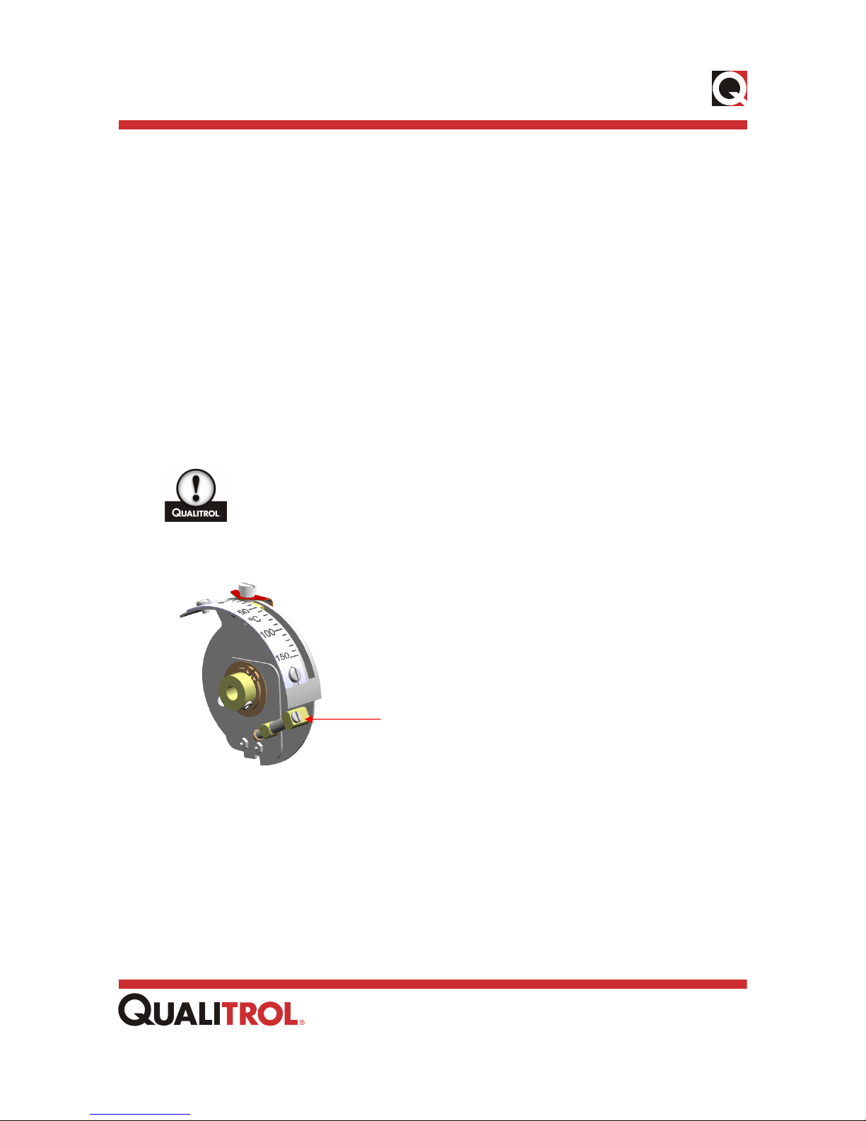
Figure 1 – Switch Setting Scale .........................................................................................2
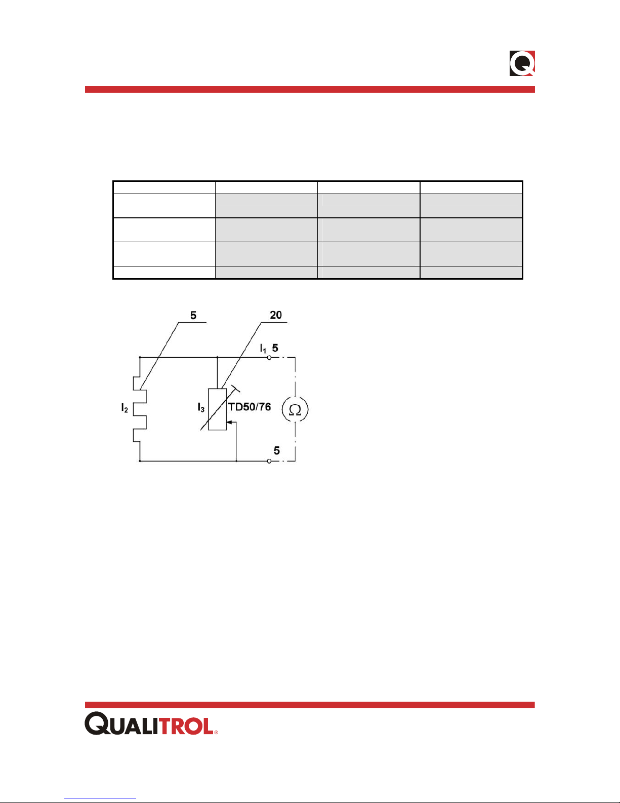
Figure 2 – TD Adjusting Schematic...................................................................................3
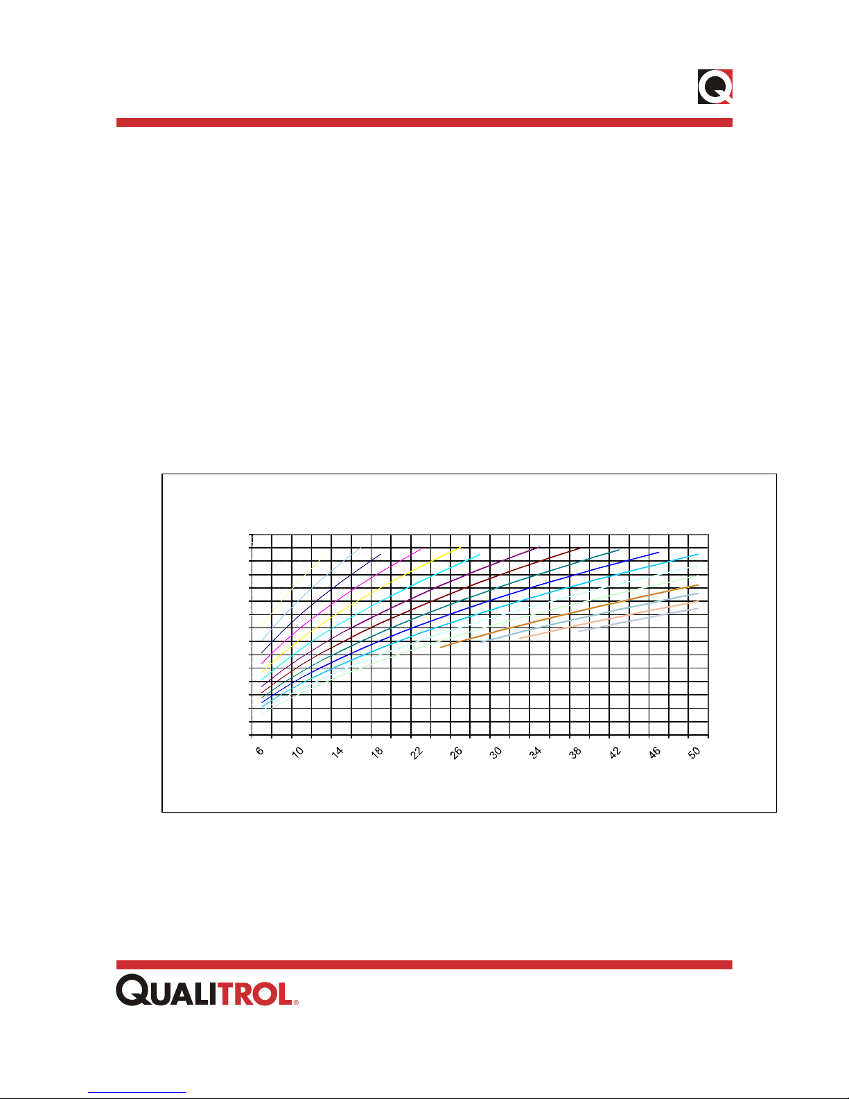
Figure 3 – Temperature Gradient Graph ...........................................................................4
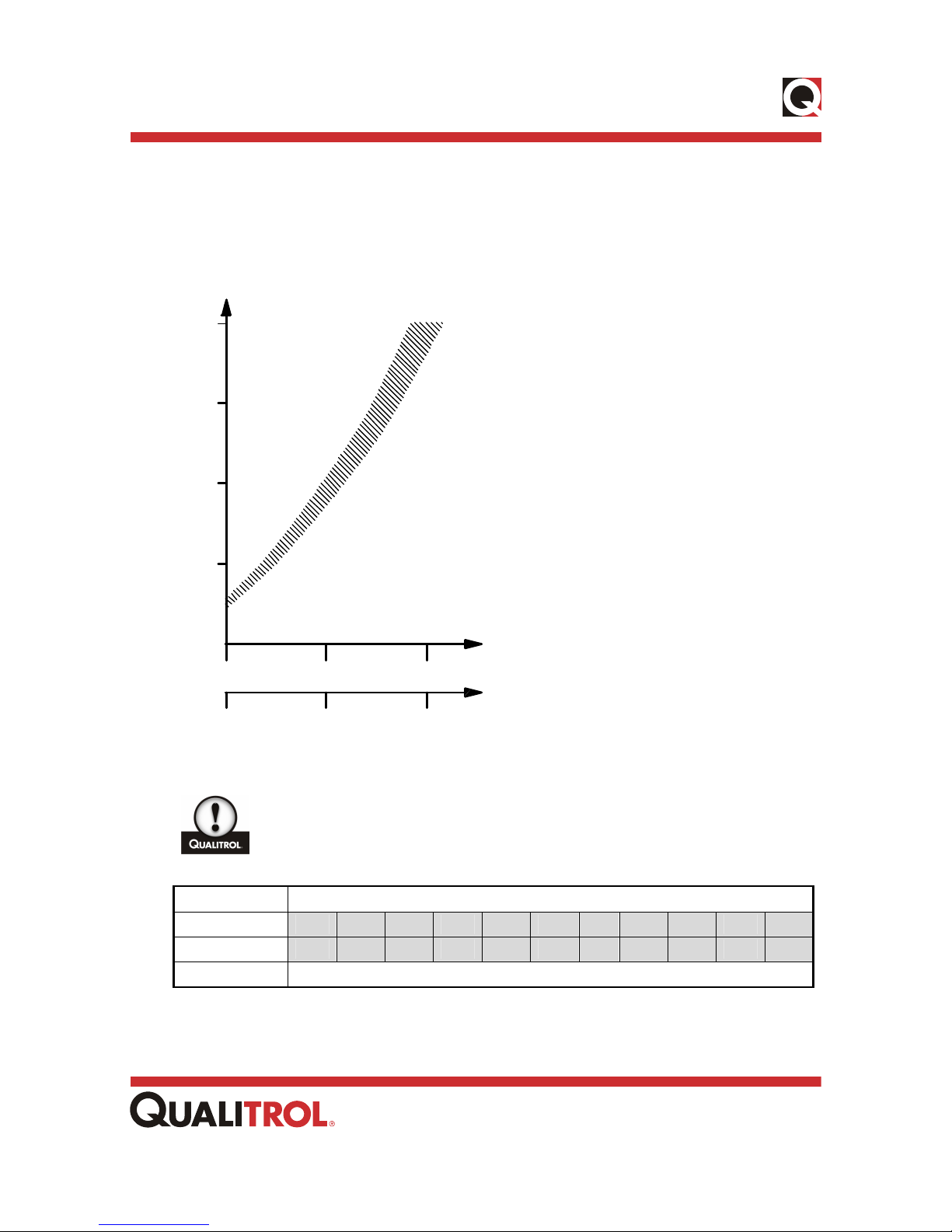
Figure 4 – Guideline for Adjustment of Heating Current .................................................5
Figure 4.1 – Guideline for wiring Double Gradient Option ..............................................6
Figure 4.2 – TD50 / 5 Amp Wiring Example.......................................................................8
Figure 5 – Siesmic Mount...................................................................................................9
Figure 6 – Universal Mount ................................................................................................9
Figure 7 – Anti-Vibration (Standard) Mount....................................................................10
Figure 8 – Cover Hinge Side View ...................................................................................11
Figure 9 – Front Cover Removal......................................................................................11
Figure 10 – Switch Selection............................................................................................12
Figure 11 – 2 to 4 Switches w/Optional Heater and Remotes .......................................13
Figure 11.1 – 2 to 4 Switches w/Optional Heater and Remotes ....................................13
(TD50 5 Amp).....................................................................................................................13
Figure 11.2 – 2 to 4 Switches w/Optional Heater and Remotes ....................................13
(Double Gradient)..............................................................................................................13
Figure 12 – 5 to 6 Switches only......................................................................................14
Figure 13 – 5 to 6 Switches w/Optional heater and Remotes........................................14
Figure 14 – Pocket/Well Installation ................................................................................15
Figure 15 – 4-20mA Suggested Wiring TD111 ................................................................19
Figure 15.1 – 0-1mA Suggested Wiring TD119-1............................................................20
Figure 15.2 – 0-5mA Suggested Wiring TD119-2............................................................21
Figure 15.3 – 0-10mA Suggested Wiring TD119-3..........................................................22
Figure 15.4 – 0-20mA Suggested Wiring TD119-4..........................................................23

Contents
Contents iii www.qualitrolcorp.com
Figure 15.5 – 4-20mA & 0-5V DC Suggested Wiring TD119-5........................................24
Figure 15.6 – 4-20mA & 0-10V DC Suggested Wiring TD119-5......................................25
Figure 15.7 – Suggested Wiring TD66 CU10/PT100 .......................................................26

AKM 345 Gen2 Instruction Manual (Rev No. ECN-27992)
1www.qualitrolcorp.com
1. General
The AKM345 next generation, GEN2 for short, is a world class, robust CE approved fully
weather proofed temperature indicator, used globally for electricity transformers. It is
designed and manufactured for long and trouble free outdoor operation under all conditions.
To secure maintenance-free operation, the installation on the transformer must
be made with care.
2. Installation
•Before installation check for possible damage from transport handling.
•Do not carry the instrument by the capillary. Do not twist the capillary when unwinding
it, or bend too sharply – min radius 25 mm. Clamp it along its entire length at approx
400 mm intervals. Excess capillary can be wound in a spiral with min diam.100 mm.
•Leave at least 15% thermal expansion space in oil filled pockets.
•The non-vibration mountings included must be used to prevent mechanical wear out
caused by transformer vibrations.
•Installation shall prevent instrument casing temperatures over +70°C for standard
types.
3. Calibration Check
•Each instrument is factory calibrated and no further calibration is required.
•Check calibration put the bulb in boiling water (+100°C) or in a well stirred bath (min
water or oil volume 5 litres) with a control thermometer. Read the thermometer after 15
minutes. If indication error is larger than 5°C we recommend contacting local agent or
manufacturer for further assistance.
4. Switch Setting
•Switches are factory calibrated.
•Each switch is individually adjustable and provided with a scale.
•Open instrument front cover by loosening the two lower retaining bolts.
•Loosen the knurled-head screw on the red pointer.
•Hold the screw in position and rotate the scale drum until the red pointer under the
knurled screw points at the desired contact point on the scale.

AKM 345 Gen2 Instruction Manual (Rev No. ECN-27992)
2www.qualitrolcorp.com
•Tighten the screw in this position.
•• Check that contact is obtained by slowly turning the shaft of the drum so that the
pointer of the temperature gauge moves towards higher values on the scale. The shaft
of the drum must not be turned in the other direction since the calibration of the
instrument may change. When checking the instrument must be in a vertical position.
4.1. (Optional) Adjustable Switch Differential Setting Instructions
•Adjust alarm set point as described above.
•Adjust the multi-turn adjusting screw located beneath the switch scale plate fully
clockwise. At this point the differential will be set at 5°C. (When turned fully anti-
clockwise the differential is set at 25°C)
•Pull down the brass test lever (located on the right hand side) slowly to verify correct
alarm and differential setting. For example if the alarm is set at 50°C and the adjusting
screw is set fully anti-clockwise, the switch will energize at 50°C on rising temperature.
It will de-energize on lowering temperature at 25°C.
Never force the test lever upwards.
•Fine-tune differential setting by gradually turning the adjusting screw.
Figure 1 – Switch Setting Scale
Adjusting Screw

AKM 345 Gen2 Instruction Manual (Rev No. ECN-27992)
3www.qualitrolcorp.com
5. Technical Data – Matching Resistance TD50/TD76
TD50 TD76 TD50/5 Amp
Max Cont. Input at
100% Load
2.2 A from CT 2.65 A from CT 5.0 A from CT
Adj. Range 0 - 80% of Input
Current from CT
45 - 85% of Input
Current from CT
0 - 35% of Input
Current from CT
Insulation 2kV, 50Hz, 60s to
Earth
2kV, 50Hz, 60s to
Earth
2kV, 50Hz, 60s to
Earth
I3Resistance 0 - 111.75 - 130 - 11
Figure 2 – TD Adjusting Schematic

AKM 345 Gen2 Instruction Manual (Rev No. ECN-27992)
4www.qualitrolcorp.com
5.1. Instructions for Adjusting Matching Resistance
1. Check or calculate current in A from Your Current Transformer (at bushing) at 100 %
transformer load.
2. Check the required Winding Temperature gradient in °C or K.
3. Use the graph in Fig.3 for the CT current and gradient to determine the required
resistance setting in Ohms. Take note of this value.
4. Connect a multi meter, (Example: Fluke) set for resistance measurement to the
terminals 5-5 inside the WTI.
5. Adjust the matching resistance TD50 or TD76 until you reach the required resistance
value. For TD50/5A see section 5.4.
6. Secure the lock nut on the matching resistance for this setting.
7. Check operation and make final adjustments if necessary.
8. Please consult Customer Service for additional information.
Figure 3 – Temperature Gradient Graph
1.2 1.3 1.41.5 1.6 1.7 1.8 1.9 2
2.1
2.2
11.1
2,3
2,4
2,5
2,6
0.40
0.60
0.80
1.00
1.20
1.40
1.60
1.80
°C
Temperature Gradient
–
Adjustment Graph-
Resistance, Ohms

AKM 345 Gen2 Instruction Manual (Rev No. ECN-27992)
5www.qualitrolcorp.com
5.2. Temperature Gradient Graph for WTI with External 1A and 5A
Matching Unit
S (VA)4,520,5
Heating Curr ent
40
30
20
2
I (A)1,510,5
10
dT °C
Gradient
Figure 4 – Guideline for Adjustment of Heating Current
Keep cover mounted, feed a stable current and wait 45 min, before reading
winding temperature.
Gradient °C for bulb type 11, 12, 15 and 18
10 12 14 16 18 20 22 24 26 28 30
Oil temp. 30°C 0,72 0,79 0,86 0,92 0,99 1,04 1,1 1,15 1,21 1,26 1,31
Heating Current Amp. I2 ±5%
Bulb in filled well.
Approximate temperature
rise above oil temperature.
Imax = 2,3 A continuously
Imax = 10 A, for 5 s
Thermal time constant
(63,2% value) approx. 9 min.

AKM 345 Gen2 Instruction Manual (Rev No. ECN-27992)
6www.qualitrolcorp.com
5.3. Wiring the AKM345 Double Gradient Option
5.3.1. Background
The Double Gradient option allows for setting two separate winding simulations in the same
Winding Temperature Indicating Thermometer. The CT input is provided with two
independently adjustable potentiometers for determining the heater current. Switching
between the heater currents is performed external to the thermometer.
5.3.2. Wiring Recommendations
The potentiometers are wired to the 56 and 57 terminal block positions. The CT input is
wired to the 5-5 positions as shown.
•To activate the 56 Gradient, jumper between the right 5-5 and 56 terminal block
position.
•To activate the 57 Gradient, jumper between the right 5-5 and 57 terminal block
position.
An example of external switch wiring is shown below.
Figure 4.1 – Guideline for wiring Double Gradient Option
5.4. Using the 5 Amp Internal CT Option

AKM 345 Gen2 Instruction Manual (Rev No. ECN-27992)
7www.qualitrolcorp.com
The AKM 345 TD50(5 AMP) option allows for the input of up to 5 amps winding temperature
simulation current without the expense or additional wiring required by an external matching
unit. It is available with up to 4 switches. The 5 amp option employs an internal CT which
accepts 5 amps at the primary and outputs 2.2 amps at the secondary. The secondary
current is in parallel with a standard TD50 matching resistance and heater. For temperature
rise calculations please refer to Figure 3.
•Accuracy of 2.2A output at 5A input:
+/-5% at 0 - 1.6 secondary load
+/-10% at 1.6 - 1.8 secondary load
•Max continuous primary current: 6A
•Max primary current: 10 a for 2 minutes
5.5. Setting the Matching Resistance
There are two methods of setting the matching resistance depending on the accuracy
required. Use Method A for maximum ease of use and Method B for maximum accuracy.
5.5.1. Method A
•Disconnect the white separable connector and using an ohmmeter at the "R" pins,
adjust the matching resistance to meet the target R5-5 value which will provide the
desired heater current (see Section 5.1 instructions).
•Re-connect the white separable connector. After the matching resistance has been set
and the white connector is re-mated, the winding simulation input current is wired to
the terminal block at the 5-5 positions as shown.
5.5.2. Method B
•Disconnect the white separable connector and using an ohmmeter at the “R” pins,
adjust the matching resistance to meet the target R5-5 value which will provide the
desired heater current (see Section 5.1instructions).
•Jumper between one pin of the "R" connector and one pin of the “I” connector, and
connect an ammeter between the remaining two pins, as shown.
•Input the desired primary current at positions 5-5 on the terminal block and note the
current flowing in the circuit. You now have the exact ratio of input to output current at
secondary load. Disconnect power before disconnecting the ammeter and jumper– the
secondary leads must always be connected in-circuit or shorted when the CT is
powered.
•Using the measured secondary current, re-calculate the desired R5-5 value which will
provide the exact heater current necessary for the desired winding simulation. Using
an ohmmeter at the “R” pins, adjust the matching resistance to meet this R5-5 value.

AKM 345 Gen2 Instruction Manual (Rev No. ECN-27992)
8www.qualitrolcorp.com
•Re-connect the white separable connector. After the matching resistance has been set
and the white connector is re-mated, the winding simulation input current is wired to
the terminal block at the 5-5 positions as shown.
TD50
POT HEATER
CT
BLK
OUT 2.2A
BLK
WHT
IN 5A
WHT
WHITE CONNECTOR
"MALE PINS"
WHITE CONNECTOR
"FEMALE PINS"
R
I
to 5-5 POSITIONS
Optional
Current
Measurement
JUMPER
Ammeter
Figure 4.2 – TD50 / 5 Amp Wiring Example

AKM 345 Gen2 Instruction Manual (Rev No. ECN-27992)
9www.qualitrolcorp.com
6. Mounting Styles and Dimensions
6.1. Seismic Mount
Figure 5 – Siesmic Mount
Special mounting for high amplitude, low frequency conditions
6.2. Universal Mount
Figure 6 – Universal Mount
Adaptor plate for many different mounting bolt patterns

AKM 345 Gen2 Instruction Manual (Rev No. ECN-27992)
10 www.qualitrolcorp.com
6.3. Anti-Vibration (Standard) Mount
Figure 7 – Anti-Vibration (Standard) Mount
Standard mounting, highest instrument isolation available

AKM 345 Gen2 Instruction Manual (Rev No. ECN-27992)
11 www.qualitrolcorp.com
7. Front Cover Removal
4.09
[104]
11.93
[303]
3.68 [93]
11.88 [302]
Figure 8 – Cover Hinge Side View
Figure 9 – Front Cover Removal
Cable glands: M25 (max 3) and M20 (max 2)
After unlocking the front cover, lift the front cover up fully, slide the top cover to
the right and remove. To refit, reverse the above instructions.

AKM 345 Gen2 Instruction Manual (Rev No. ECN-27992)
12 www.qualitrolcorp.com
8. Contact Rating / Breaking capacity
RATED
VOLTAGE
RESISTIVE
LOAD
INDUCTIVE
LOAD
125 VAC 15 A 15 A
250 VAC 15 A 15 A
30 VDC 15 A 10 A
125 VDC 0.75 A 0.4 A
250 VDC 0.3 A 0.3 A
125 VAC 10 A 6 A
250 VAC 3 A 1.5 A
30 VDC 10 A 10 A
125 VDC 10 A 6 A
250 VDC 3 A 1.5 A
30 VDC 0.1 A -
125 VDC 0.1 A -
125 VAC 10 A 6 A
250 VAC 10 A 4 A
30 VDC 10 A 4 A
125 VDC 0.5 A 0.05 A
250 VDC 0.25 A 0.03 A
125 VAC 15 A 15 A
250 VAC 15 A 15 A
30 VDC 6 A 5 A
125 VDC 0.5 A 0.05 A
250 VDC 0.25 A 0.03 A
GW
STANDARD
SWITCH
MBO
GOLD
DPDT
Figure 10 – Switch Selection
•MBO = Magnetic Blow Out, high DC switching, minimum Electrical Operations =
100,000 Cycles, all others 500,000 cycles minimum.
•GOLD = Typically used for low current low voltage applications, e.g., SCADA or
computer connections.
•DPDT = Double Pole Double Throw, 2 x changeover contacts.
•GW = Similar to Gold and used for high DC voltage and low current applications.
Switch Selection: Select switch type (default is 15A), this will be applied to all
switches. Select the number of switches to be adjustable, (default is 0), then
select the switch differential of the remaining switches. This will automatically
default to 12± 2°C.

AKM 345 Gen2 Instruction Manual (Rev No. ECN-27992)
13 www.qualitrolcorp.com
9. Terminal Block Arrangements
Figure 11 – 2 to 4 Switches w/Optional Heater and Remotes
Figure 11.1 – 2 to 4 Switches w/Optional Heater and Remotes
(TD50 5 Amp)
Figure 11.2 – 2 to 4 Switches w/Optional Heater and Remotes
(Double Gradient)

AKM 345 Gen2 Instruction Manual (Rev No. ECN-27992)
14 www.qualitrolcorp.com
Figure 12 – 5 to 6 Switches only
Figure 13 – 5 to 6 Switches w/Optional heater and Remotes
For options not shown, please consult Configuration Form or contact
QUALITROL Customer Service Centre.

AKM 345 Gen2 Instruction Manual (Rev No. ECN-27992)
15 www.qualitrolcorp.com
10. Pocket/Well Installation
Figure 14 – Pocket/Well Installation
This manual suits for next models
3
Table of contents
Other Qualitrol Measuring Instrument manuals