manuals.online logo
Brands
  1. Home
  2. •
  3. Brands
  4. •
  5. Quality Water Treatment
  6. •
  7. Water Dispenser
  8. •
  9. Quality Water Treatment Fleck 5600 SXT User manual

Quality Water Treatment Fleck 5600 SXT User manual

Page 1 of 14
Copyright © 2009 Quality Water Treatment, All right reserved. rev. 10.29.09 www.qualitywatertreatment.com
INSTALLATION & START-UP INSTRUCTIONS
FLECK 5600 SXT Metered WATER SOFTENER
Thank you for your purchase of a new Water Softener
with Fleck 5600SXT Meter water softener from Quality
Water Treatment! We have put together these
instructions as a reference, and they are to be used as a
general installation guideline.
Pre-Installation Guide
Before you assembly your new system, be sure that the
following conditions have been met for placement of your
system:
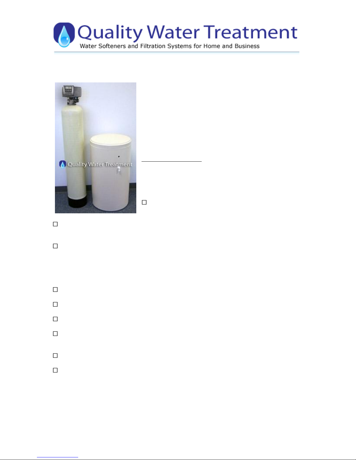
Level, firm surface, such as concrete, on which to place the
softener tank and salt tank AKA Brine Tank
Nearby floor drain or standpipe to connect to the softener for use during each
regeneration
Standard US plug, 120v 60hz (the softener system includes a 5ft. power cord and plug. Be
sure the plug is not connected to a light switch
Make a list of all the plumbing fittings to completely install the unit
Typical is:
Two - 3/4" or 1” male adaptors
Eight - 90°elbows
Amount of pipe you need
1/2" drain line and 90°elbows
Adding the Resin to the Water Softener Tank
1. Position your new softener unit where you want it placed for use.
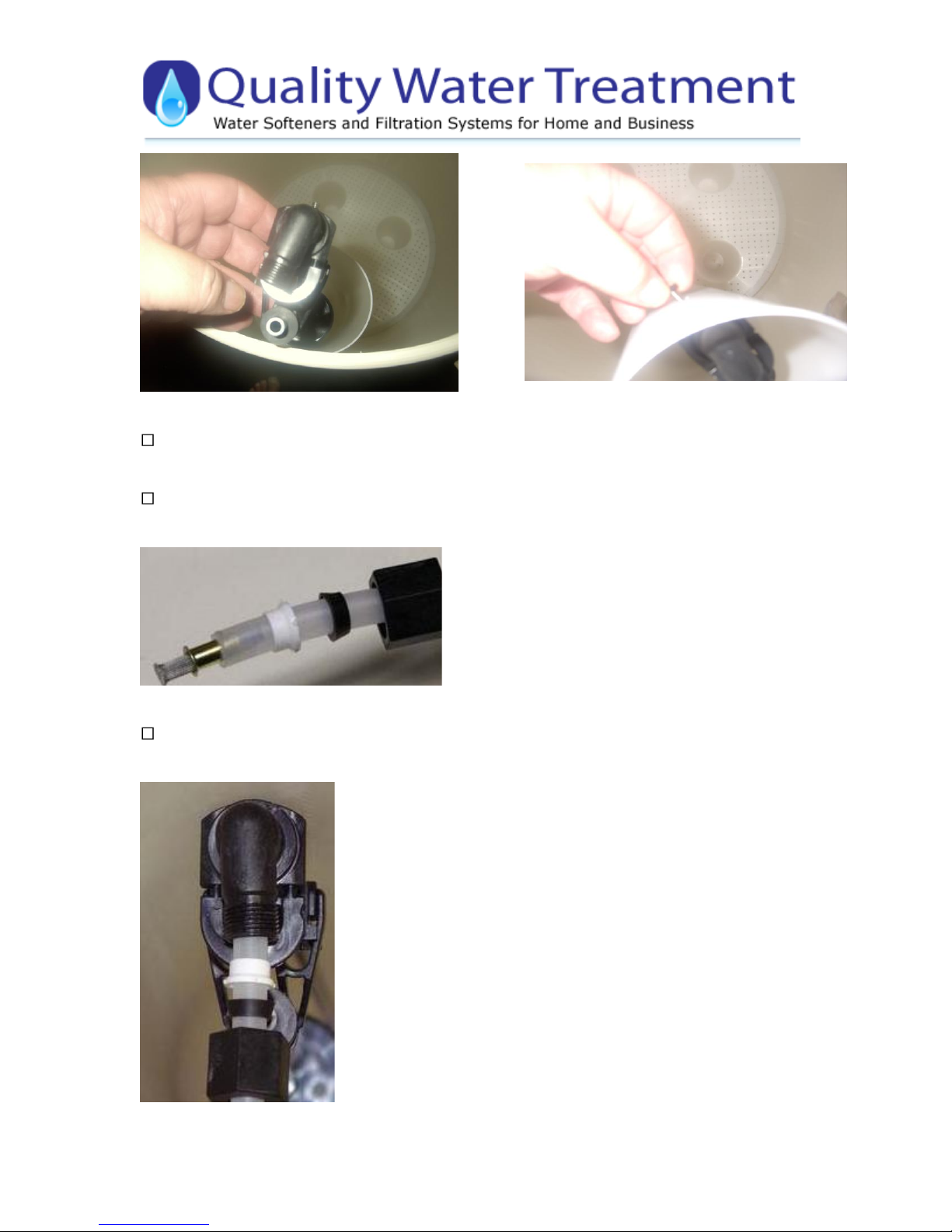
2. Inside the Softener tank you’ll find a 3/4" or 1" gray or white Pvc tube (called a
distributor tube.) If the tube does not already have a cap on the top use a pvc slip cap or
some duct tape to temporarily plug this tube (this is to keep the resin from going down the
tube.) If your system came with gravel, add the gravel first, then the resin. Use the included
special funnel when adding the resin. This will take about 10 minutes.
Page 2 of 14
Copyright © 2009 Quality Water Treatment, All right reserved. rev. 10.29.09 www.qualitywatertreatment.com
After adding the resin, remove the temporary cap, clean the valve threads with water, and
screw the valve on. When screwing the valve on the tank the tube will slip into the bottom of
the valve hole. Note no silicone or tape is needed, the valve is o’ring fit and only needs to
be tightened by hand.
Assemble all tools needed to install the unit. Start your Installation. If copper, you need a
copper cutter, propane tank, soldering torch, flux, wire paper and lead free solder. An
average cost of $40.00 NOW THAT YOU HAVE ADDED THE RESIN AND CONNECTED THE
CONTROL VALVE TO THE TANK YOU ARE READY TO INSTALL, FOLLOW THESE
INSTRUCTIONS:
1. Turn off the main water shutoff valve.
2. Open all plumbing fixtures in the house including all outside faucets in order to drain the
lines. Unscrewing the aerator screen from your kitchen and bathroom faucets will help drain
the lines faster
3. Cut and remove a 4" section of the water line where the unit is to be installed.
4. Remove the two stainless steel clamps that are connected between the stainless steel bypass
valve and the plastic meter assembly, there is one clamp on each side. Remove the bypass
valve from the meter assembly by pulling it away from the meter assembly.
Page 3 of 14
Copyright © 2009 Quality Water Treatment, All right reserved. rev. 10.29.09 www.qualitywatertreatment.com
.
5. Leave the meter assembly in place.
6. We do not recommend applying heat from a soldering torch to solder copper pipe to your
new valve/meter assembly. To help with this:
Solder a 3" to 5" piece of ¾" OR 1" copper pipe into each male adapter.
Now that the pieces of ¾" OR 1" copper pipe are soldered into the adapters, wait until
they are cool enough to touch. Apply Teflon tape or Pipe joint compound to both male
threads, and thread them and tighten them into the By-pass valve before you attach it onto
the back of the valve/meter.
Re-attach the stainless bypass valve back onto the valve/meter assembly and secure it with
the two small stainless steel clamps.
7. Now position the water softener unit in place for final water line installation, making sure
the bypass valve is set in the "BYPASS"
8. FIRST, measure and cut the lengths of pipe you need to plumb the main hard water line
into your softener unit. Then do the same for the soft water line that will exit from the
softening unit, back out into the house.
9. NOTE: The unit will be marked either on the back of the valve body itself with the word
"IN" and "OUT" or the top of the body of the bypass valve assembly with arrows showing the
direction of water flow into and out of the valve. "Out: is the water entering your house after
it has passed through the water softener. BE VERY CAREFUL TO MAKE SURE YOU PLUMB THE
SYSTEM IN THE RIGHT DIRECTION OTHERWISE YOU WILL LOOSE THE RESIN OUT OF THE
TANK INTO YOUR HOUSE LINES!
Page 4 of 14
Copyright © 2009 Quality Water Treatment, All right reserved. rev. 10.29.09 www.qualitywatertreatment.com
Use tephlon tape only and wrap around the threaded end of the drain line adaptor and
screw drain line adaptor into control show in photo below, then snug up with a small wrench.
Note: you do not have to tighten real tight doing so well crack the backwash assembly
housing.
Attaching your drain line: Note: Do not attach the drain line to the elbow on the brine tank
it will overflow the brine tank. Running the drain line to a house drain, where your washing
machine drain line goes is an excellent choice, if this is not possible then you can drain into
multiple areas, make sure you always leave an air gap if going into a pipe. An air gap is an
open area where there is no standing water. Your drain line can be elevated up to 5 feet
over and above where it comes out of the valve and you can run it up to 100 feet away.
Always follow local codes.
Slide a 1/2" hose clamp over drain line and then slide drain line over drain hose barb.
Slide hose clamp over barb and tube and tighten the hose clamp.
Plug your power cord into a nearby outlet. Plug you meter cable into the top side of the black
meter dome in the back of the system like photo below shows.
Page 5 of 14
Copyright © 2009 Quality Water Treatment, All right reserved. rev. 10.29.09 www.qualitywatertreatment.com
Assembly of Brine tank:
The float assembly is a safety float; it only functions if there’s a failure in the control valve.
This will insure the brine tank won’t overflow with water. The safety float does not dictate the
water level in your brine tank. Measure from the top of the air check shown as # 1, 10" to
bottom of float show as #2 in photo below, you may have to gently push the float rod
through the rubber gametes to achieve this. Cut any existing rod off.
Slide the float assembly into the brine well shown in photo below and stick the stud into the
side hole on the brine well shown in photo below and secure it with the nut we supplied you.
Page 6 of 14
Copyright © 2009 Quality Water Treatment, All right reserved. rev. 10.29.09 www.qualitywatertreatment.com
Take the clear brine tubing that we supplied and slide it through the whole in the brine tank
and into the brine well.
Slip the plastic nut, and the two ferules one black and one white, over brine tubing then
push brass insert and screen into brine tubing as shown in photo below.
Insert tube into top fitting on float shown in photo below and hand tighten then snug it up
with a small wrench. Note: no tape is required this is a compression fitting.
Page 7 of 14
Copyright © 2009 Quality Water Treatment, All right reserved. rev. 10.29.09 www.qualitywatertreatment.com
Take the other end of tube slide the Nut and Farrell over it and insert sleeve in to tube. Push
the tube into the side of the control valve show in photo below. Tighten by hand then snug it
up with a small wrench.
Programming the Fleck 5600SXT Water Softener control valve:
A few simple steps must be followed to program the Fleck 5600SXT Meter Valve.
It will be important to know what your water Hardness and Iron content is before doing this
programming procedure. If you do not know your water hardness or iron content you should
either look up your city water quality report by going to Google and typing in: water quality
report enter you water supply company or the city that you are in, or take a 8 oz sample to a
pool supply store or send one to us to have it tested.
Your Hardness test results may indicate GPG, PPM, or Mg/L. It is important to note that PPM
and Mg/L are the same measure and both figures can be treated interchangeably. If you get
a hardness figure in PPM or Mg/L, please divide this number by 17.1 to get Grains Per
Gallon “ GPG”
Iron results should also be measured in either PPM or Mg/L. Add your level of iron multiplied
by 3. Add this number to your hardness level. This figure will be your Total hardness content
that you will program into your softener system. Example if water hardness is 10 GPG and
the iron is 1 PPM or Mg/L take the iron content of 1 and x 3 = 3 GPG hardness plus 10
GPG = total compensated hardness 13 GPG
First plug in your 5600SXT Valve to a nearby outlet. The system will illuminate 4 digits and
show the time of day and the amount of gallons remaining. This display will switch between
these values about every 5 seconds.
Set the time on the system to 12:01 PM by pressing either the UP or DOWN arrow as shown
in picture below. You can hold the button to allow the time to scroll faster.
Page 8 of 14
Copyright © 2009 Quality Water Treatment, All right reserved. rev. 10.29.09 www.qualitywatertreatment.com
Once the time display is set to 12:01 PM, press the “extra cycle button once as shown in the
photo below.
Extra cycle button
To enter master programming mode, press the UP and DOWN buttons together and hold for
5 seconds, and then release the buttons, as shown in picture below.
The display should now show DF GAL as shown in the picture below. This indicates United
States gallons. Do not change this value, and press the Extra Cycle Button once to continue.
Page 9 of 14
Copyright © 2009 Quality Water Treatment, All right reserved. rev. 10.29.09 www.qualitywatertreatment.com
The display should now show VT St1b as shown in the picture below. This indicates Valve Type
5600 Mode) Do not change this value, and press the Extra Cycle Button once to continue.
The display should now show CT / Fd as shown in the picture below. This indicates Control
Type Meter Delayed. Do not change this value, and press the Extra Cycle Button once to
continue.
The display should now show NT - - - 1 as shown in the picture below. This indicates number
of tanks is single. Do not change this value, and press the Extra Cycle Button once to
continue.
Page 10 of 14
Copyright © 2009 Quality Water Treatment, All right reserved. rev. 10.29.09 www.qualitywatertreatment.com
The display should now show C 24.0 as shown in photo below. This indicates the Capacity is
24,000 grains Use the UP or DOWN button to change this value to the size of your system,
and press the Extra Cycle Button once to continue when finished.
The display should now show H 20 as shown in picture below. This indicates the Hardness is 20
grains) Use the UP or DOWN button to change this value to the total hardness of your
water. Then press the Extra Cycle Button once to continue when finished.
The display should now show RS SF as shown in the picture below. This indicates Reserve
Selection is Safety Factor percentage do not change this value, and press the Extra Cycle
Button once to continue.
Page 11 of 14
Copyright © 2009 Quality Water Treatment, All right reserved. rev. 10.29.09 www.qualitywatertreatment.com
The display should now show SF 10 as shown in the picture below. This indicates the Safety
Factor is 10 percent. Use the UP or DOWN button to change this value to 15. Press the
Extra Cycle Button once to continue when finished.
The display should now show DO 14 as shown in the picture below. This indicates the Day
Override is 14 days the system will regenerate on the 14TH day if the meter does not
otherwise automatically initiate a regeneration based on gallons used. Do not change this
value, and press the Extra Cycle Button once to continue.
The display should now show RT 2:00 as shown in picture below. This indicates the system will
regenerate at 2:00AM, assuming the system clock is set accurately. Press the Extra Cycle
Button once to continue.
Page 12 of 14
Copyright © 2009 Quality Water Treatment, All right reserved. rev. 10.29.09 www.qualitywatertreatment.com
The display should now show BW 10 as shown in the picture below. This indicates Backwash
Time is 10 minutes. Do not change this value, and press the Extra Cycle Button once to
continue.
The display should now show BD 60 as shown in picture below. This indicates Brine Draw Time
is 60 minutes. Do not change this value, and press the Extra Cycle Button once to continue.
The display may now show RR 10 as shown in picture below. This indicates Rapid Rinse Time is
10 minutes) Do not change this value, and press the Extra Cycle Button once to continue if
this value is different, use the UP or DOWN buttons to change it.
Page 13 of 14
Copyright © 2009 Quality Water Treatment, All right reserved. rev. 10.29.09 www.qualitywatertreatment.com
The display may now show BF 12 as shown in picture below. This indicates the length of the
Brine Refill Cycle during regeneration. Do not change this value, and press the Extra Cycle
Button once to continue. If this value is different, use the UP or DOWN buttons to change
it.
The display may now show FM t0.7 as shown in picture below. This indicates Flow Meter type
3/4" Turbine. Do not change this value, and press the Extra Cycle Button once to continue
if this value is different, use the UP or DOWN buttons to change it.
The system will now exit the Master Programming mode, and the display should now show the
time of day, followed by the new number of gallons remaining, as shown in the picture below.
Change the time of day by pressing and holding the UP or DOWN button until the proper
time setting is shown. There is a PM light indicator to show the difference between AM
and PM times.
Page 14 of 14
Copyright © 2009 Quality Water Treatment, All right reserved. rev. 10.29.09 www.qualitywatertreatment.com
Your 5600SXT Water Softener System is now programmed and ready for operation.
Filling your water softener with water and purging air from it: Turn all faucets off outside
and in home. Slowly open bypass valve and let the mineral tank fill with water. When water
stops running go to the nearest treated faucet to the Water Softener, unscrew aerator screen
if applicable and turn cold water on slowly, this will bleed the air from the tank, let the water
run until it clears. If you sized your water softener using our recommendation then you will go
through salt or potassium chloride slowly. Add five gallons of water to brine tank. Add three
40 to 50 pound bags of extra course, pelt salt or potassium chloride to brine tank. The resin is
already charged so initial regeneration is not required.
Installation and set up is now complete. Congratulations! Please fill free to email some pictures
of you new installation and a letter we will post it on our site for other customers to view. As
always we appreciate your business!

Other Quality Water Treatment Water Dispenser manuals

Quality Water Treatment SoftPro Natural Soft Series User manual

Quality Water Treatment

Quality Water Treatment SoftPro Natural Soft Series User manual

Quality Water Treatment Prosoft Elite User manual

Quality Water Treatment

Quality Water Treatment Prosoft Elite User manual

Quality Water Treatment SoftPro User manual

Quality Water Treatment

Quality Water Treatment SoftPro User manual

Quality Water Treatment SOFTPRO ELITE User manual

Quality Water Treatment

Quality Water Treatment SOFTPRO ELITE User manual

Quality Water Treatment SoftPro Elite CITY WATER User manual

Quality Water Treatment

Quality Water Treatment SoftPro Elite CITY WATER User manual

Quality Water Treatment SOFTPRO ELITE User manual

Quality Water Treatment

Quality Water Treatment SOFTPRO ELITE User manual

Popular Water Dispenser manuals by other brands

Kogan KA2ICDISPSA quick start guide

Kogan

Kogan KA2ICDISPSA quick start guide

Lancaster PACESETTER 7-PEL-75B Installation, operating and service manual

Lancaster

Lancaster PACESETTER 7-PEL-75B Installation, operating and service manual

Culligan MC405 operating manual

Culligan

Culligan MC405 operating manual

Avanti WDT40Q3S-IS instruction manual

Avanti

Avanti WDT40Q3S-IS instruction manual

Asset SORGENTE Installation, user and maintenance manual

Asset

Asset SORGENTE Installation, user and maintenance manual

Watts Pure Water SmartStream UV PWA002 Installation, operation and maintenance manual

Watts

Watts Pure Water SmartStream UV PWA002 Installation, operation and maintenance manual

Royal Sovereign RWD-250W owner's manual

Royal Sovereign

Royal Sovereign RWD-250W owner's manual

Hellenbrand H200M HE owner's manual

Hellenbrand

Hellenbrand H200M HE owner's manual

Kinetico Premier Series owner's manual

Kinetico

Kinetico Premier Series owner's manual

Elkay EZTL Series Installation and use manual

Elkay

Elkay EZTL Series Installation and use manual

US Water Systems Waterlogix WLS-075 Installation, operation and maintenance manual

US Water Systems

US Water Systems Waterlogix WLS-075 Installation, operation and maintenance manual

GE GXOF18G Owner's manual and installation instructions

GE

GE GXOF18G Owner's manual and installation instructions

Electrolux EQALF01TXSP user manual

Electrolux

Electrolux EQALF01TXSP user manual

Hellenbrand AQUA Systems SmartChoice Gen II O3 Installation, operation and service manual

Hellenbrand

Hellenbrand AQUA Systems SmartChoice Gen II O3 Installation, operation and service manual

USTM LOTUS user manual

USTM

USTM LOTUS user manual

Coway BB09-A user manual

Coway

Coway BB09-A user manual

Avalon A8CTBOTTLELESSWHT user manual

Avalon

Avalon A8CTBOTTLELESSWHT user manual

Lancaster Water Treatment X-FACTOR Series Installation, operating and service manual

Lancaster Water Treatment

Lancaster Water Treatment X-FACTOR Series Installation, operating and service manual

manuals.online logo
manuals.online logoBrands
  • About & Mission
  • Contact us
  • Privacy Policy
  • Terms and Conditions

Copyright 2025 Manuals.Online. All Rights Reserved.