manuals.online logo
Brands
  1. Home
  2. •
  3. Brands
  4. •
  5. QualityWaterForLess.com
  6. •
  7. Water Dispenser
  8. •
  9. QualityWaterForLess.com Fleck 5600SXT Meter Installation manual

QualityWaterForLess.com Fleck 5600SXT Meter Installation manual

© 1999-2007 QualityWaterForLess.com - 1 - [email protected]
INSTALLATION & START-UP
INSTRUCTIONS
FLECK 5600SXT METER
WATER SOFTENER SYSTEMS
© 1999-2007 QualityWaterForLess.com - 2 - [email protected]
Preface:
Thank you for your purchase of a new Water Softener with Fleck 5600SXT Meter from
QualityWaterForLess.com! We have put together these instructions as reference, and to
be used as general installation guidelines. It is always recommended that a licensed
plumber perform all installation work according to all local codes. We at
QualityWaterForLess.com cannot assume responsibility for improper installation,
application, or injury or damage as a result of improper installation.
Pre-Installation Guidelines:
Before assembly of your new system, be sure that the following conditions have been met
for placement of your system:
•Level, firm surface, such as concrete, on which to place the softener tank and salt
tank (as known as a ‘brine’ tank)
•Nearby floor drain or standpipe to connect to the softener for use during each
regeneration
•Un-switched power source, standard US plug, 120v 60hz (the softener system
includes a 5ft. power cord and plug)
•Access to the water main coming into your home. You will need to install the
softener at this point to assure that water for the home is going through the
system.
Placing and Filling the Tank:
•Choose the final location for your water softener tank, and place the tank upright
and level on the surface.
•Filling the tank may be necessary on some systems. Your tank may have also
come prefilled, and in this case you only need to unscrew the protective cap as
shown below in Figure 1 and move on to the next section.
FIGURE 1
© 1999-2007 QualityWaterForLess.com - 3 - [email protected]
•If your tank is not filled, please follow the additional instructions below.
•First, place the riser tube into the tank as shown in Figure 2. NOTE: Please be
sure that the riser tube seats into the bottom of the tank, and that the top of
the riser tube is FLUSH with the top of the tank lip.
FIGURE 2
•Before filling the tank, place a piece of duct tape over the top of the riser to
prevent resin from dropping down inside the riser tube as shown in Figure 3.
•Place the included filling funnel over the top the the tank as shown in Figure 4,
and prepare to fill the tank. If your softener system came with Gravel, please pour
this amount into the tank FIRST, then pour in the included resin media
afterwards.
FIGURE 3 FIGURE 4
•Remove the filling funnel and duct tape and go on to the next section
© 1999-2007 QualityWaterForLess.com - 4 - [email protected]
Installing the Fleck 5600SXT Meter Control Valve:
•Using the included silicone lubricant packet, lubricate the inner and outer o-
rings on the bottom of the Fleck 5600SXT Meter Valve as shown in Figures 5
& 6 below.
FIGURE 5 FIGURE 6
•Next, place the Fleck 5600SXT Meter Valve onto the top of the tank, being
sure that the riser tube fits into the central o-ring on the valve, as shown in
figure 7 below. Hand tighten the valve to the tank snugly by hand only.
NOTE: Do not use Teflon tape or pipe dope on the valve or tank threads.
FIGURE 7
•Locate the plumbing adaptor that was shipped with your system. Also,
disassemble the plumbing adaptor clips as shown in Figure 8 on the following
page.
•Using the included silicone lubricant packet, lubricate the o-rings on the Fleck
5600SXT Meter valve as shown in figure 9 on the following page.
•Finally, assemble the plumbing adaptor to the valve as shown in Figure 10 on
the following page. When assembling the clips back onto the valve, leave the
first clip loose. Tighten the second clip, and complete the assembly by
tightening the first clip.
© 1999-2007 QualityWaterForLess.com - 5 - [email protected]
FIGURE 8 FIGURE 9
FIGURE 10
Plumbing your Fleck 5600SXT Meter:
•Before beginning your installation, please first familiarize yourself with the “IN”
and “OUT” on the Fleck 5600SXT Meter Valve. In order to prevent damage to
your home and to the softener system, install the softener according to the
“IN” and “OUT” arrows on the softener valve!
•Find the main shut-off valve for your house and turn it to the “OFF” position. If
you have a private well, this valve should be near your well pressure tank. If you
have a city water supply, your valve should be near your water meter.
•Depressurize and drain your home of water by turning on all faucets and fixtures
in your home, including those outside.
© 1999-2007 QualityWaterForLess.com - 6 - [email protected]
•Pick your installation point, and cut a section of pipe out to run to and from your
softener. NOTE: In many cases, it is preferred to keep outside lines
UNSOFTENED. If you wish to keep your outside lines unsoftened, you must
plumb “Bypass” lines to run hard water to these fixtures.
•Using soldered copper, PVC plastic pipe, or flexible connections, plumb the
system according to all local plumbing codes. NOTE: If using copper pipe,
please pre-fabricate at least a 12” section of pipe for the “IN” and “OUT”
bound lines and use a wet rag on the lines being soldered to prevent heat
damage during soldering!
•Once all connections have been made, place the system into bypass by either
using your existing 3-valve bypass (if ordered with a Yoke adaptor), or by
switching your included bypass to “BYPASS” (if ordered with a Bypass)
•Next, gradually open your main valve and allow all air in your plumbing lines to
escape slowly. Also, you may turn off all outside and inside faucets and fixtures.
•Check for leaks at your plumbing site for signs of slow drips, and rectify if
necessary.
•Please do not take the softener out of “BYPASS” as the installation is completed
yet! NOTE: Please take this opportunity to check and re-check the “IN” and
“OUT” to make sure that they are correct!
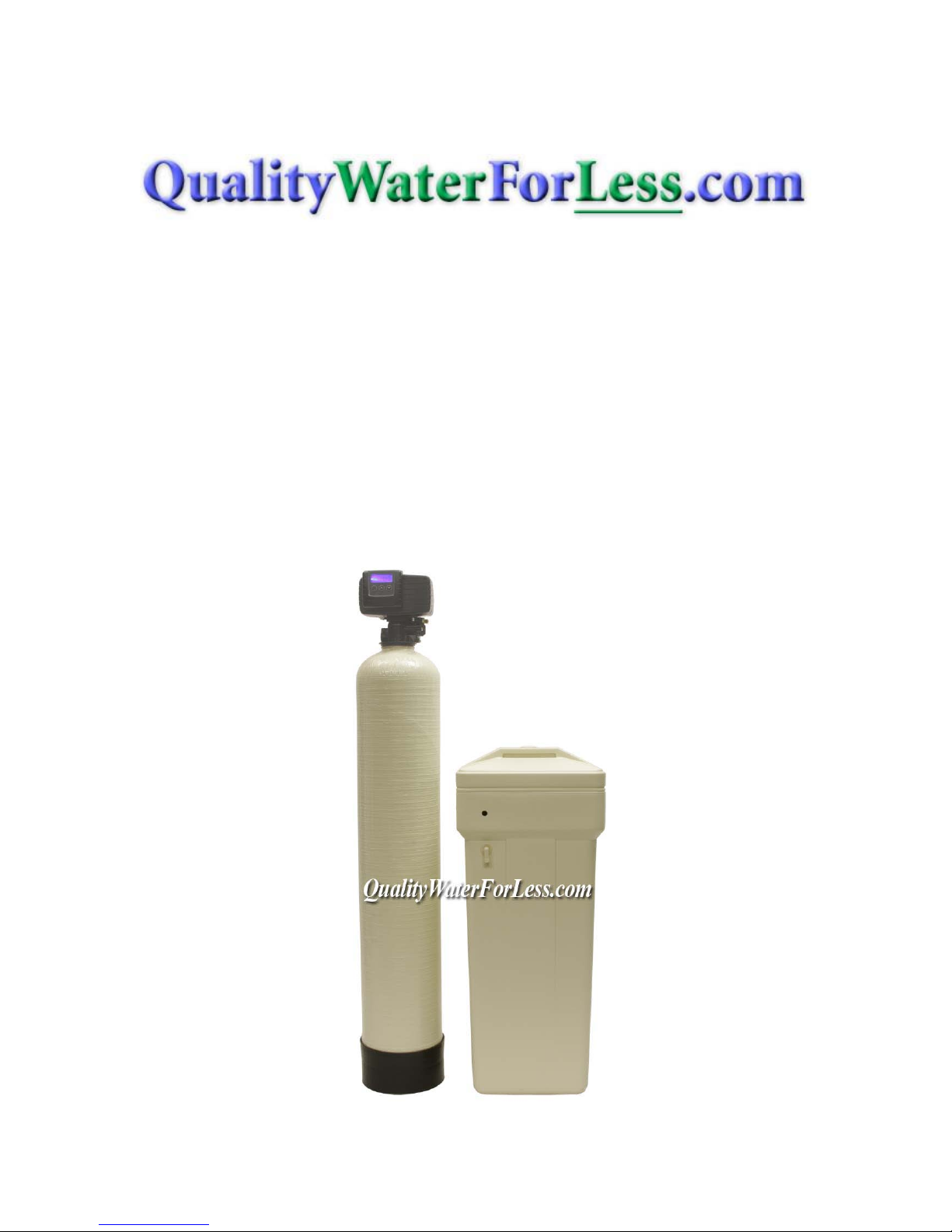
Making the Brine Tank Connection:
•onto one side of the included Brine Tubing as shown in Figure 11 below.
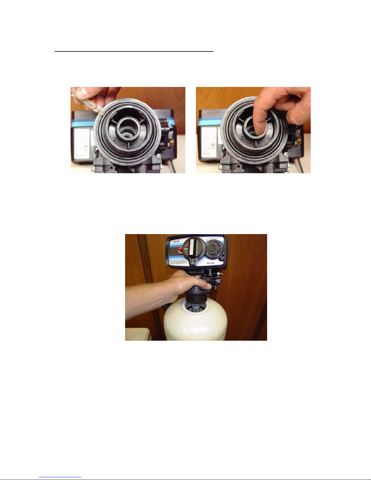
•Next, connect to the Fleck 5600SXT Meter Valve as shown in Figure 12 below.
FIGURE 11 FIGURE 12
•Tighten the nut to the valve using a wrench until snugly in place. Be careful not to
over tighten, as you may sever the brine line tubing.
•Locate the included brine tank, and remove the brine tank cover shown on the
following page in Figure 13.
•Next, locate the brine well, and remove the cap as shown in Figure 14 on the
following page.
© 1999-2007 QualityWaterForLess.com - 7 - [email protected]
FIGURE 13 FIGURE 14
•Pull the 2310 brine float assembly out of the brine well and disassemble the
retaining nut as shown in Figure 15 below.
•Next, assemble the 2310 brine float assembly to the brine well through the pre-
drilled hole and hand-tighten as shown in figure 16 below.
FIGURE 15 FIGURE 16
•Take the other end of your brine line tube and insert the tube through the small
hole drilled through the brine tank, and brine well. Loosely unscrew the hex nut
on the 2310 brine float assembly. Insert the tubing end firmly into the hex nut on
the 2310 brine float assembly.
•Next back-off the hex nut and ferrule assembly so they are securely onto the
tubing as shown in Figure 17 on the following page. NOTE: Please be sure to
assemble the nut in the fashion described to prevent system malfunction and
possible brine tank overflow!
•Hand-tighten the hex nut snugly onto the 2310 brine float assembly as shown in
Figure 18 below.
© 1999-2007 QualityWaterForLess.com - 8 - [email protected]
FIGURE 17 FIGURE 18
•Finally, use ½” I.D. tubing to connect the drain bard fitting on the brine tank to a
floor drain as shown in Figure 19. NOTE: This is not necessary as the 2310
assembly is designed to prevent an overflow situation, , but is a good and
recommended precaution for a proper installation.
FIGURE 19
Making the Drain Connection:
•Locate the included barbed fitting and use Teflon tape to wrap the threading.
Install the fitting to the Fleck 5600SXT Meter Valve by screwing the fitting using
a wrench snugly into the drain port as shown in Figure 20 on the following page.
Please use caution not to over tighten this fitting.
•Next, assemble your ½” I.D. drain line to the drain barb as shown in Figure 21 on
the following page. Be sure to use rigid wall ½” I.D. tubing that will not flatten!
© 1999-2007 QualityWaterForLess.com - 9 - [email protected]
FIGURE 20 FIGURE 21
•Wrap electrical tape over the drain tubing to prevent a tubing split, and clamp the
tubing securely into place with the included blue clamp as shown in Figure 22
below.
FIGURE 22
•Connect the other end of this drain line tubing SECURELY to a standpipe or
drain in accordance with all local plumbing codes. NOTE: Be sure that the
drain line is securely in place before the use of the water softener system.
When the system regenerates, there will be increased flow via this tubing,
which may cause the tubing to become loose.
Programming the Fleck 5600SXT Meter Valve:
•Before start-up a few simple steps must be followed to program the Fleck
5600SXT Meter Valve.
•It will be important to know what your water’s Hardness and Iron content is
before doing this programming procedure. If you do not know your water
hardness, or if you are unsure, you may wish to have it tested by sending us a
sample for testing, or by taking a sample to a local pool supply, or hardware store.
© 1999-2007 QualityWaterForLess.com - 10 - [email protected]
•Your Hardness test results may indicate “Grains”, “PPM”, or “mg/L”. It is
important to note that PPM and mg/L are the same measure and both figures can
be treated interchangeably. If you get a hardness figure in PPM or mg/L, please
divide this number by 17.1 to get Grains. Ex: If your hardness is measured at
300 PPM, your Grains are 300 / 17.1 = 18 Grains.
•Your Iron results should also be measured in either “PPM” or “mg/L”. Add your
level of iron multiplied by 5. Add this number to your hardness level. This final
figure will be your Total Hardness Level that we will program into your softener
system. Ex: If your iron level is measured at 5 PPM, add 5 x 5 = 25 Grains of
hardness to existing hardness total.
•To begin programming, first plug in your 5600SXT Valve to a nearby wall outlet.
The system will illuminate 4 digits. The system will show the time of day and the
amount of gallons remaining. This display will switch between these valves about
every 10 seconds.
•Set the time on the system to 12:01 PM by pressing either the “UP” or “DOWN”
arrow as shown in figure 23 below. You may hold the button to allow the time to
scroll faster.
•Once the time display is set to 12:01 PM, press the “extra cycle” button once as
shown in figure 24 below.
FIGURE 23 FIGURE 24
•To enter master programming mode, press the “UP” and “DOWN” buttons
TOGETHER and HOLD for 5 seconds, and then release the buttons, as shown in
figure 25 below.
•The display should now show “DF / GAL” as shown in figure 26 below. (This
indicates U.S. Operation Mode - Gallons) Do not change this value, and press
the “Extra Cycle Button” once to continue.
FIGURE 25 FIGURE 26
© 1999-2007 QualityWaterForLess.com - 11 - [email protected]
•The display should now show “7VT / St1b”as shown in figure 27 below. (This
indicates Valve Type 5600 Mode) Do not change this value, and press the
“Extra Cycle Button” once to continue.
•The display should now show “CT / Fd” as shown in figure 28. (This indicates
Control Type METER Delayed Format) Do not change this value, and press the
“Extra Cycle Button” once to continue.
FIGURE 27 FIGURE 28
•The display should now show “NT / - - - 1” as shown in figure 29 below. (This
indicates Number of Tanks is Single) Do not change this value, and press the
“Extra Cycle Button” once to continue.
•The display should now show “C / 32.0” as shown in figure 30 below. (This
indicates the Capacity is 32,000 grains) Use the “UP” or “DOWN” button to
change this value to the size of your system, and press the “Extra Cycle
Button” once to continue when finished.
FIGURE 29 FIGURE 30
•The display should now show “H / 20” as shown in figure 31 below. (This
indicates the Hardness is 20 grains) Use the “UP” or “DOWN” button to
change this value to the total hardness of you water (as calculated on page
10), and press the “Extra Cycle Button” once to continue when finished.
FIGURE 31
© 1999-2007 QualityWaterForLess.com - 12 - [email protected]
•The display should now show “RS / SF” as shown in figure 32 below. (This
indicates Reserve Selection is Safety Factor percentage) Do not change this
value, and press the “Extra Cycle Button” once to continue.
•The display should now show “SF / 20” as shown in figure 33 below. (This
indicates the Safety Factor is 20 percent) Use the “UP” or “DOWN” button to
change this value to “15”, and press the “Extra Cycle Button” once to
continue when finished.
FIGURE 32 FIGURE 33
•The display should now show “DO / 14” as shown in figure 34 below. (This
indicates the Day Override is 14 days – the system will regenerate on the 14th day
if the meter does not otherwise automatically initiate a regeneration based on
usage.) Do not change this value, and press the “Extra Cycle Button” once to
continue.
•The display should now show “RT / 2:00” as shown in figure 35 below. (This
indicates the system will regenerate at 2:00 AM, assuming the system clock is set
accurately) Although this is the recommended time, you may change this by
using the “UP” or “DOWN” buttons, and then press the “Extra Cycle
Button” once to continue.
FIGURE 34 FIGURE 35
•The display should now show “BW / 10” as shown in figure 36 on the following
page. (This indicates Backwash Time is 10 minutes in length) Do not change this
value, and press the “Extra Cycle Button” once to continue.
•The display should now show “BD / 60” as shown in figure 37 on the following
page. (This indicates Brine Draw Time is 60 minutes) Do not change this value,
and press the “Extra Cycle Button” once to continue.
© 1999-2007 QualityWaterForLess.com - 13 - [email protected]
FIGURE 36 FIGURE 37
•The display may now show “RR / 12” as shown in figure 38 below. (This
indicates Rapid Rinse Time is 10 minutes) Do not change this value, and press
the “Extra Cycle Button” once to continue – if this value is different, use the
“UP” or “DOWN” buttons to change this.
•The display may now show “BD / 10” as shown in figure 39 below. This indicates
the length of the Brine Refill Cycle during regeneration. Use the table below to
determine the proper salt time setting based on the size of your system – if
this value is different, use the “UP” or “DOWN” buttons to change this..
Change the value by pressing the “UP” or “DOWN” button until the proper
time setting is shown, and press the “Extra Cycle Button” once to continue
when finished.
FIGURE 38 FIGURE 39
System Size
Salt Time Setting
24,000 Grains
7
32,000 Grains
10
40,000 Grains
12
48,000 Grains
15
64,000 Grains
19
80,000 Grains
23
96,000 Grains
29
120,000 Grains
39
© 1999-2007 QualityWaterForLess.com - 14 - [email protected]
•The display may now show “FM / t0.7” as shown in figure 40 below. (This
indicates Flow Meter type 3/4" Turbine) Do not change this value, and press
the “Extra Cycle Button” once to continue – if this value is different, use the
“UP” or “DOWN” buttons to change this.
•The system will now exit the Master Programming mode, and the display should
now show the time of day, flowed by the new number of gallons remaining, as
shown in figure 41 below. Change the time of day by pressing and holding the
“UP” or “DOWN” button until the proper time setting is shown. Note that
there is a “PM” light indicator to differentiate between AM and PM times.
FIGURE 40 FIGURE 41
•Congratuations! Your new 5600SXT system is now programmed and ready for
operation. Please move on to the next section on the following page to initialize
and start-up your system.
© 1999-2007 QualityWaterForLess.com - 15 - [email protected]
Initial Start-Up:
•With one nearby softened faucet running in the COLD position, slowly open your
bypass valve or 3-valve bypass to about ¼ open to allow the air trapped in the
softener to escape via your running faucet. NOTE: Opening the bypass too
quickly or too open may damage your softener or plumbing.
•Allow the softener tank to slowly fill with water. After a few minutes, you will
see a trickle of water coming from the cold water faucet. Allow the water to run
slowly in this manner for an additional 5 minutes. Next, with the cold water faucet
still running, gradually move your bypass valve to the fully open position.
NOTE: You may see some initial discoloration from the softened water – this
is normal and should dissipate within the first 40-50 gallons of water used.
•Turn off the nearby cold water faucet when the water runs clear.
•Add approximately five gallons of water to your brine tank, and add 120-160
pounds of pellet, solar, or block salt or potassium chloride to your brine tank.
Enjoy Your Softener!
Congratulations, you have successfully installed your new water softener with Fleck
5600SXT Meter Valve!
Please maintain your system by keeping the softener plugged-in and always keep your
brine tank filled with salt to at least above the water level.
We appreciate your business, and hope that you enjoy years of trouble-free softened
water!
- QualityWaterForLess.com

Popular Water Dispenser manuals by other brands

Avanti WD001 instruction manual

Avanti

Avanti WD001 instruction manual

Watts HC-300 manual

Watts

Watts HC-300 manual

Campomatic CHW3070 instruction manual

Campomatic

Campomatic CHW3070 instruction manual

Elkay ESWA8 1L Series Installation, care & use manual

Elkay

Elkay ESWA8 1L Series Installation, care & use manual

Primo Water 900139 user manual

Primo Water

Primo Water 900139 user manual

Whirlpool HD1000XSC7 Installation instructions and use and care guide

Whirlpool

Whirlpool HD1000XSC7 Installation instructions and use and care guide

BRIO Premiere CBP500 Series user manual

BRIO

BRIO Premiere CBP500 Series user manual

Omnifilter BF35 installation instructions

Omnifilter

Omnifilter BF35 installation instructions

HydrogenX Hydro6000x instruction manual

HydrogenX

HydrogenX Hydro6000x instruction manual

H2O H2O-56SE-R-48 manual

H2O

H2O H2O-56SE-R-48 manual

Angel W-Y1251LKY-ROM Instruction guide

Angel

Angel W-Y1251LKY-ROM Instruction guide

Primo Water B264 manual

Primo Water

Primo Water B264 manual

Beko BSS 4600 TT user manual

Beko

Beko BSS 4600 TT user manual

Grunbeck softliQ:MC operating manual

Grunbeck

Grunbeck softliQ:MC operating manual

HELLER WFC user manual

HELLER

HELLER WFC user manual

AquaticLife 540371 Installation, operation and maintenance guide

AquaticLife

AquaticLife 540371 Installation, operation and maintenance guide

Delta ESCALDA installation guide

Delta

Delta ESCALDA installation guide

Tier1 WS-165-150 Series owner's manual

Tier1

Tier1 WS-165-150 Series owner's manual

manuals.online logo
manuals.online logoBrands
  • About & Mission
  • Contact us
  • Privacy Policy
  • Terms and Conditions

Copyright 2025 Manuals.Online. All Rights Reserved.