Quattro Titanium EGO400 User manual

Ref: QUATTRO500/600-UM
UK
REF: UM 1.0
Model No. EGO400 - Titanium
Model No. EM4446 - Enduro
REMOTE CARAVAN MOVER
Installation guide and user
information.
UK

i
UK
DE
NL
FR
ES
IT
Bitte besuchen Sie www.purpleline.co.uk/caravan-movers VOR Installation auf Aktual-
isierungen zu Produktspezikationen, Nutzung, Sicherheit und Einbauvorschriften zu
überprüfen.
Kunt u terecht op www.purpleline.co.uk/caravan-movers vóór de installatie te controleren
of er updates over productspecicaties, het gebruik, de veiligheid of de installatie-instruc-
ties.
Please visit www.purpleline.co.uk/caravan-movers BEFORE installation to check for any
updates on product specications, usage, safety or installation instructions.
Si prega di visitare www.purpleline.co.uk/caravan-movers prima dell’installazione per veri-
care eventuali aggiornamenti sulle speciche di prodotto, l’uso, la sicurezza o le istruzioni
per l’installazione.
Se il vous plaît visitez www.purpleline.co.uk/caravan-movers avant l’installation pour véri-
er les mises à jour sur les spécications des produits, l’utilisation, la sécurité ou les instruc-
tions d’installation.
Por favor, visite www.purpleline.co.uk/caravan-movers ANTES de la instalación para com-
probar si hay actualizaciones sobre especicaciones de productos, el uso, la seguridad o las
instrucciones de instalación.

3
3
3
3
4
4
4
4
2
2
2
2
+
+
+
+
1
1
1
1
-
-
-
-
1
2
3
4
5
68
9
10
11
12
13
14 15
16
17
18
19
20
21
22
23
24 25
26
27
28
30
31
32
7
Motor A
Motor B
29
Fig.A
33

Fig.1
Fig.2 Fig.3
A
B
C
D
E
F
G
H
A
B
C
A
B
C
D
E
F
G
A
Fig.4
Fig.6
A
B
Fig.5
A
EGO400
EGO400
EM4446
EM4446
A
B
C
D
E
F
G

Fig.11 Fig.12
Fig.13
20mm
A
EGO400
EGO400
EGO400
Fig.7 Fig.8
Fig.10
20mm
A
Disengaged
Position
Disengaged
Position
Engaged
Position
Engaged
Position
EM4446
EM4446
EM4446

Fig.16
Fig.14
Fig.15
185mm
(min)
30mm to 45mm
165mm
(min)
85mm (min)
2.8mm to 3.5mm
1800mm to 2500mm (max)
Fig.18
Fig.17
L – Profile U – Profile
Caravan Floor
CONTROL
UNIT
BATTERY
Fig.19
A
10mm
EGO400/
EM4446
A
A
B
C
Motorside

Fig.20
+-
+-
12
34
+-
A
B
Fig.21 Motor
A
Motor
B
Draufsicht
Bovenaanzicht
Overhead View
Vista dall’alto
Vue aérienne
Vista superior
Motor
B
Motor
A
Vorderseite des Wohnwagens
Voorkant caravan
Caravan Front
Direzione di marcia
Avant de la caravane
Frontal de la caravana

Fig.22

Ref: EGO4446/EGO400-UM-Rev.B. UK 1
ITable of Contents
Package Contents (Parts List) Page 1
Introduction Page 2
Fitting Guidelines Page 2
Specications Page 2
Installation Safety Guidelines Page 2,3
Installation - Mechanical Components Page 3,4
Installation - Electrical/Electronic Components Page 4,5
Operation Safety Guidelines Page 6
Operation - Motor Units Page 7
Operation - Remote Control Handset Page 7,8
Operation - Electronic Control Unit Page 8
Before First Use - Single Axle and Twin Axle Modes Page 8
Before First Use - Pairing the Handset and Control Unit(s) Page 8
Using Your Caravan Mover with Quattro® Technology Page 9
Operation - Getting Started Page 9
Operation - Hitching and Unhitching Page 9
Maintenance Page 10
Trouble-Shooting Page 10,11
Guarantee Page 12
Package Contents (Fig.A)
Ref Qty Description Ref Qty Description
1 1 Motor Unit (A) 19 20 P-Clip Screws - M4x15
2 1 Motor Unit (B) 20 10 Cable Trunking P-Clips 19.2mm
3 1 Main Cross Bar 21 10 Cable P-Clips 10.4mm
4 1 Cross Actuation Centre Bar 22 4 Battery Terminal Connector 8mmØ
5 2 Cross Actuation Insert Bars 23 2 Battery Terminal Connector 6mmØ
6 1 Engagement Tool 24 6 Cable Spade Connectors
7 2 Classic Stop Bolts & Nuts (2 pairs) 25 3 Cable Number Markers (1,2,3,4)
8 2 Upper Classic Clamp Plate* 26 3 Cable Polarity Markers (+,-)
9 2 Classic U Plate* 27 4 Motor Unit Cable Ties 8x400
10 2 Lower Classic Clamp Plate* 28 10 Cable Ties 2x70
11 1 Convoluted Cable Trunking 29 1 Power Isolation Switch + Key + Fixings
12 2 Positive (+) Red Motor Cable 5m 30 2 Roller Distance 20mm Spacers
13 2 Negative (-) Black Motor Cable 5m 31 1 Remote Control Handset
14 1 Positive (+) Red Battery Cable 1.8m 32 1 Electronic Control Unit
15 1 Negative (-) Black Battery Cable 1.6m 33 3AAA type 1.5V Batteries (not illustrated)
16 8 Classic Clamp Bolts - M10x55* 34 2Shark Clamp Mounting System*
17 8 Classic Clamp Nylock Nuts M10*
18 8 Classic Clamp Washers 10mmØ*
* Depending on model, either classic clamp or shark
clamp will be supplied.

Ref: EM4446/EGO400-UM-Rev.B. UK 2
Thank you for choosing this caravan mover. This product has been produced according to very high standards and has undergone
careful quality control procedures. Simply by using the remote control you can move your caravan eortlessly into any position
required within operating guidelines.
Before proceeding with installation and starting to use the mover, please read this manual very carefully and be aware of
all the safety instructions! The owner of the caravan will always be responsible for correct use. Keep this manual inside
your caravan for future reference.
This User Manual covers two models of Caravan Mover: Model No. EGO400 and Model No. EM4446; any installation or operational
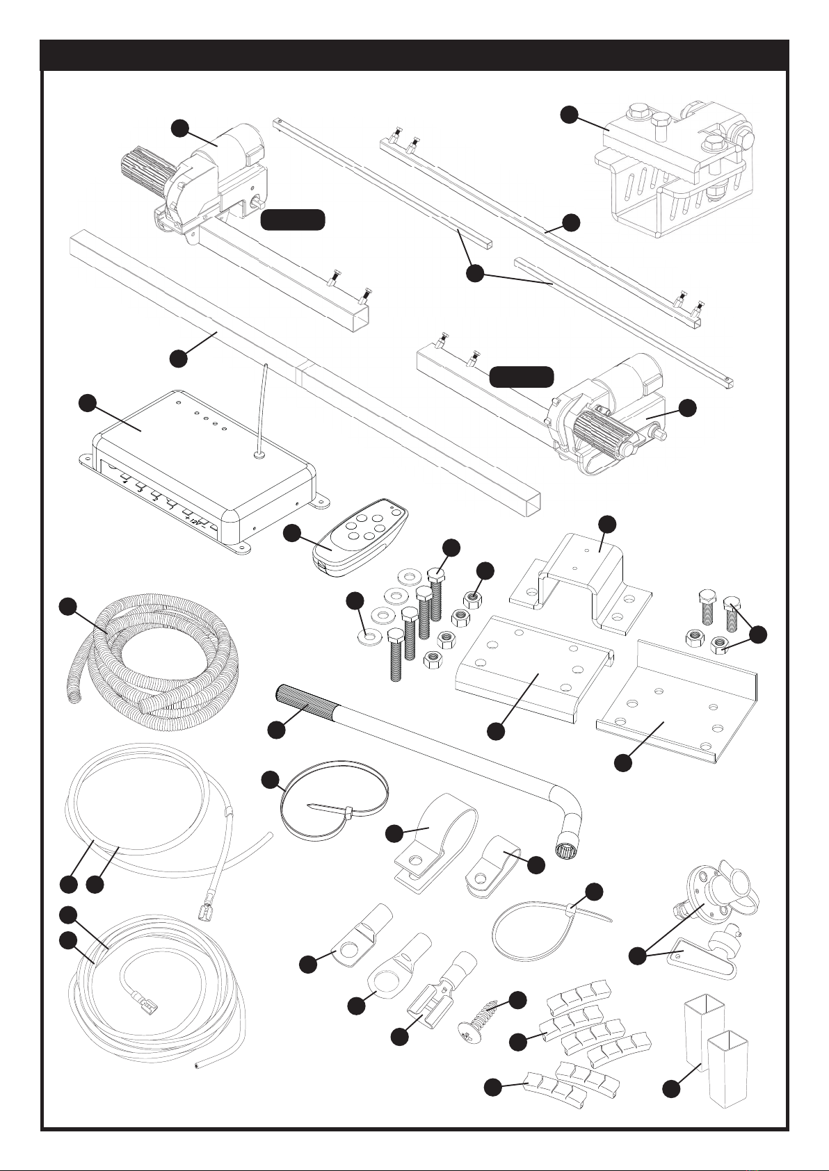
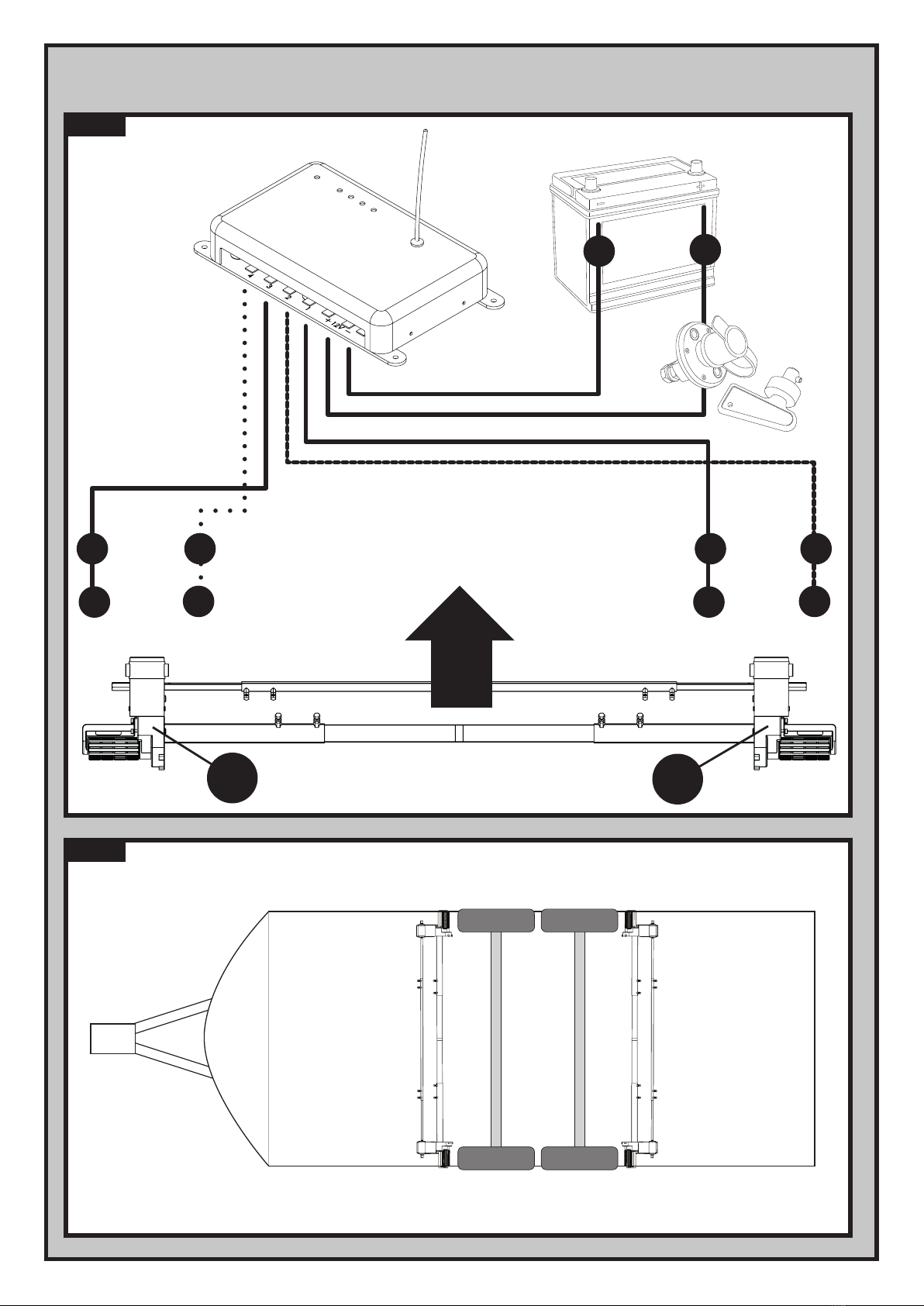
dierences between the two models are detailed where appropriate. The caravan mover consists of two 12V motor-powered
rollers, a 12V electronic control box and a remote control. To function, the motor-powered rollers must be engaged against the
tyres of your caravan. The supplied cross actuation device enables you to engage both rollers at the same time from one side of
your caravan. Once this is done the mover is ready for operation. The remote control will allow you to move your caravan in any
direction.
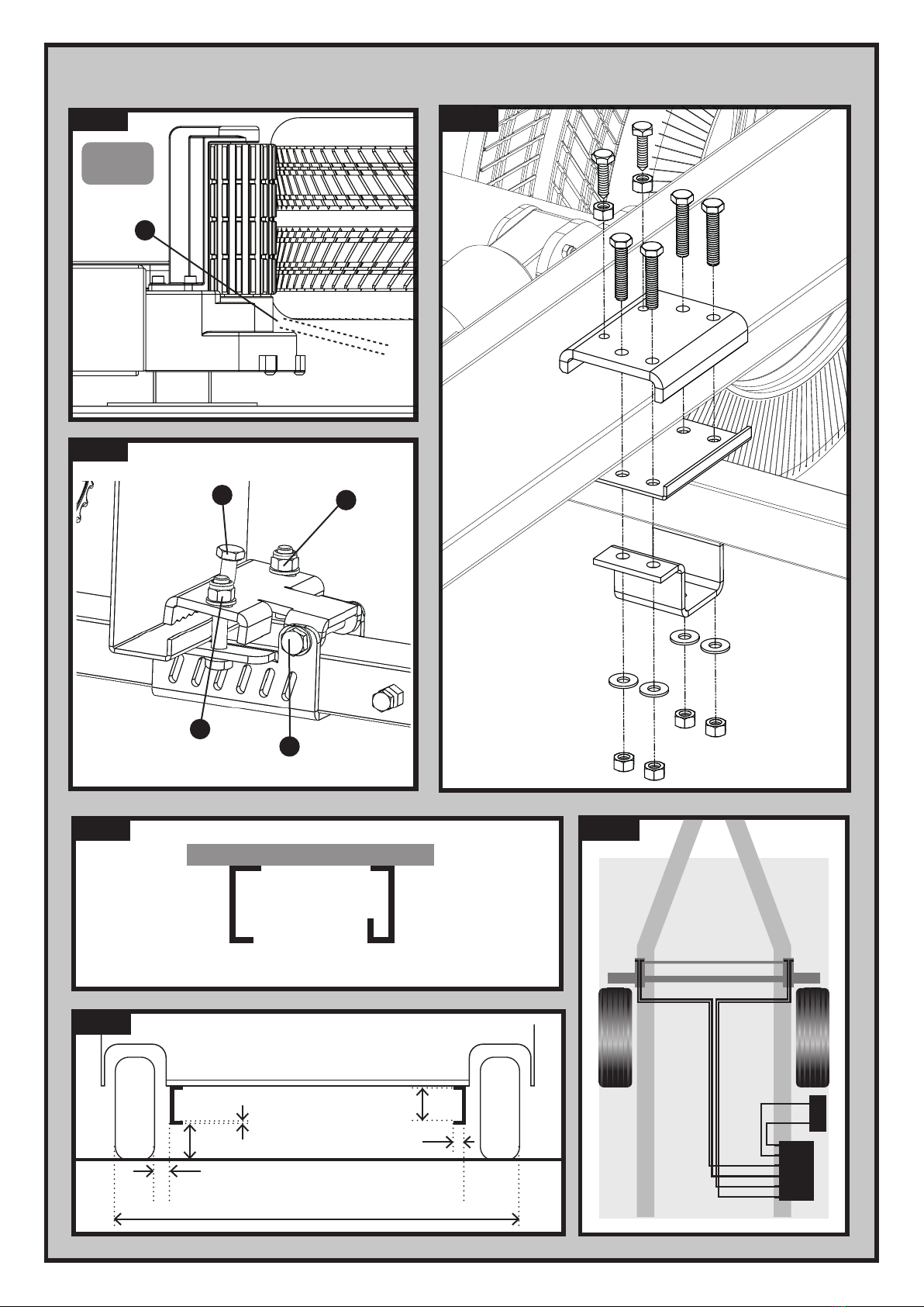
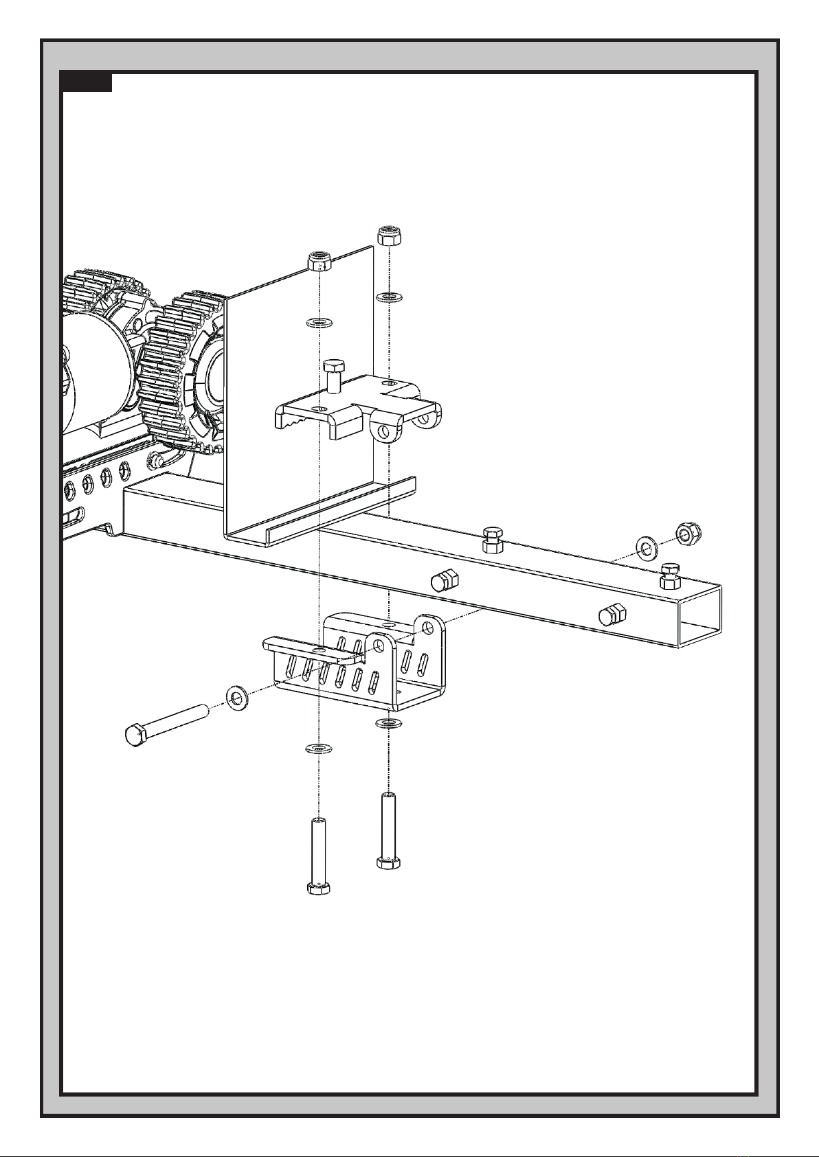
The chassis clamps provided are suitable for tment onto most standard caravan chassis that have an L-shape or U-shape prole.
Please refer to Fig.17 & Fig.18 for reference on dimensions and clearances BEFORE you proceed any further with installation.
If your chassis has dierent dimensions to those shown in Fig.18 then various chassis clamp adapters are available to suit the
majority of UK and Continental caravans; please refer to the section entitled ‘Optional Fitting Adapters’.
Note: Adjustment of this manner is only available with the Classic Clamp option.
* Average Current Consumption readings when using an approx. 1100Kg single axle caravan on a hard, level surface.
** Maximum Current Consumption readings when using an approx. 1100Kg single axle caravan ascending a 1:4 (25%) gradient.
These symbols identify important safety precautions.
They mean CAUTION! WARNING! SAFETY FIRST! IMPORTANT INFORMATION!
Specications
Installation Safety Guidelines
Important Safety Instructions
Read this User Manual carefully before installation and use. Failure to comply with
these rules could result in serious injury or damage to property.
Introduction
Fitting Guidelines
Model Number EGO400 EM4446
Operational Voltage 12 Volt DC 12 Volt DC
Average Current Consumption* 25 Ampere (approx) 25 Ampere (approx)
Maximum Current Consumption** 76 Ampere (approx) 76 Ampere (approx)
Speed 12cm per sec. (approx) 9cm per sec. (approx)
Approx. Net Weight (inc. all xings & accessories) 35 Kg 40 Kg
Safe Working Load (SWL) Twin Motor/Quad Motor 2250Kg/3500Kg 2250Kg/3500Kg
Minimum Width (caravan/trailer) 1800mm 1800mm
Maximum Width (caravan/trailer) 2500mm 2500mm
Power Source (caravan leisure battery) 12V 12V

Ref: EGO4446/EGO400-UM-Rev.B. UK 3
Before starting installation under the caravan:
DO check that the caravan is disconnected from the battery supply and the mains electrical supply.
DO only use adapters and accessories that are supplied or recommended by the manufacturer.
DO check that the tyres are not over worn (tting to new or nearly new tyres is the best option).
DO make sure that the tyre-pressures are correct to the manufacturer’s recommendation.
DO make sure the chassis is in good condition without any damage and is free from rust, dirt etc.
DO stop work immediately if you are in doubt about the assembly or any procedures and consult one of our engineers.
DO locate the battery isolation switch to be accessible at all times when parking and moving the caravan.
DO NOT remove, change or alter any parts of the chassis, axle, suspension or brake mechanism.
DO NOT operate the unit if you are under the inuence of drugs, alcohol or medication that could impair your ability to use the
equipment safely.
Installation - Mechanical Components
These instructions are for general guidance. Installation procedures may vary depending on
caravan type.
Use appropriate support! Working under a vehicle without appropriate support is extremely
dangerous.Ifyouarettingthemoversystemyourself,itisadvisablethattheinstallationis
conducted by two people, as the mover will need to be raised up to the bottom of the caravan’s
chassis before the clamps can be installed.
Remember to complete the product registration form with the serial numbers of each motor
assemblypriortotment(seedetailswithintheGuaranteesectionofthismanual).
If with your particular model of mover the motors are not pre-assembled onto the framework, please
follow assembly manual supplied in the motor packaging.
Place the caravan on a hard, level surface. The use of a lifting ramp or an assembly pit is ideal for access and personal safety.
Cleantheareaofyourchassiswhereyouneedtomountallcomponentstoensureagoodtting.
Unpackallthecomponentsandcheckforthepresenceofallparts(seePackageContentsList).
Make sure the caravan is prepared for installation. Check before installation that important areas, such as drains/spare tyre etc. do
not cause any obstruction to the function of the mover.
EnsurebothrollersareintheDISENGAGEDposition(Fig.8orFig.12),astheunitwillnottcorrectlyotherwise.
Looselyassemblemotorframeworkside(1),motorframeworkside(2)andmaincrossbar(3)(seeFig.1).Thenuts(Fig.1B)onthe
crossbar(3)mustbenomorethannger-tightatthisstage.
Placetheassembly(Fig.1)looselyunderthecaravan.Inprinciple,theunitshouldbettedinfrontofthecaravanroadwheels,but
ifttinginthispositionisnotpossible,itispermissibletotittotherearofthewheelsbyrotatingthewholeassemblyby180°
degrees.
Looselytthetwoclampingassembliestothechassis(seeFig.16)andattachusingthebolts,nutsandwashers(16,17,18)provided
intheinstallationkit.Nutsmustbenomorethannger-tight.
Assemblethepartsofthecrossactuationbar(4&5)andconnectthemtothemotorunits(1&2)withthenylocknutandbolt(in
bagofbolts)ontothecrossactuationbar-connectors(seeFig.1A).Nutsmustbenomorethannger-tightatthisstage.
Installation - Classic Clamping System (Fig.10.1)

Ref: EM4446/EGO400-UM-Rev.B. UK 4
Make sure the 12V supply from the battery and any 230V electricity supply are disconnected.
Find a suitable place for the Electronic Control Unit (32), such as a storage area, under a seat or a bed. Make sure this place is dry
and close to the battery (30 cm to 60 cm). The unit can be mounted on the bottom (horizontal) or on the wall (vertical). When
choosing location, ensure that the unit or antenna cannot easily be damaged.
Fix the Electronic Control Unit securely into position with four screws (19). Note: if the provided screws are not of
suitable length or type for the desired location/material please substitute these as appropriate.
Installation - Electrical/Electronic Components
MakesurethattheMainCrossBar(3)andtheCrossActuationCentreBar(4)arepositionedinthemiddleofthecaravan/mover(the
centreofthebarismarked).
Withthemainassemblylooselyttedontothechassis,slidethewholeassemblyalongthechassisuntiltherollers
(Fig.2AorFig.4A)are20mmawayfromthesurfaceofthecentreofeachtyre(Fig.8orFig.12).Two20mmspacers(30)areprovided.
It is vitally important that each roller is at exactly the same distance away from the tyre. The whole
assembly must be parallel to the caravan/trailer axle.
Ideally,aligntheroller(s)withthecentreofeachtyre,ifclearancespermit.Whenpositioning,alwaysensurethereisatleast10mm
ofclearancebetweenthegearboxandthetyre(Fig.14).
Fullytightenthefournylocknuts(17)onbothclampingassemblies(Fig.16)toatorquesettingof40ftlbs/55Nm,thenthe four
bolts(Fig.1B)ontheMainCrossBar(3)andthefourbolts(Fig.1C)onCrossActuationassembly(4&5)toatorquesettingof9ft
lbs/12Nm.Re-checkthedistanceof20mmfromtherollerstothetyresandifnecessary,loosentheboltsandre-adjusttheposition
of the assembly. Oncesatisedwiththepositionoftheassembly,tandtightentheChassisStopNuts&Bolts(7),onepairin
each of the Upper Classic Clamp Plates (seeFig.16).Tightentoatorquesettingof40ftlbs/55Nm.TheStopBoltsgripthelipofthe
chassis and help prevent the mover from sliding along the chassis. The main mechanical components have now been installed.
Installation - Quick-t Shark Clamp System (Fig.15)
Looselyassemblethemaincrossbar(3)insidemotorframeworkside(1)andmotorframeworkside(2)(seeFig.1).Thenuts/bolts
(Fig.1B)onmotorframework(1&2),mustbenomorethannger-tightatthisstage.
Placetheassembly(Fig.1)looselyunderthecaravan.Inprinciple,theunitshouldbettedinfrontofthecaravanroadwheels,but
ifttinginthispositionisnotpossible,itispermissibletotittotherearofthewheelsbyrotatingthewholeassemblyby180°
degrees.
TypicallytheSharkClampwillbepre-assembledontothemotorsidesforeaseoftting,butiftheclampshavebeenpurchased
seperatelyorarenotpre-assembled,theyshouldbeassembledontotheframeworkasshownin(Fig.22).Beforeattemptingto
installthemoverontoyourcaravanchassisensurethatthepinchbolts(Fig.15B)areremovedandputsafelytotheside.
Inturn,openeachjawtoitswidestposition(loosennutsFig.15Aifrequired)andhangthemotorsideframeworkontothechassis.If
thecaravanchassisisatallUprole,thenuts(Fig.15A)mayneedtoberemovedrsttoallowthejawstobeopenedwideenough.
Loosenthecrossbarnuts/bolts(Fig.1B)andadjustthelateralpositionofeachmotorsidesothattherollersarecentraltothetyre,
orasclosetothecentreaspossible,ensuring10mmofspaceisleftbeweenthetyreandgearbox(Fig.14).Afteradjustingensure
theclampshaven’tmovedoutofpositionbyholdingtheframeworkmotorsidermly,whilereachingroundandpushingthe
clampsoutwardsuntilthefasteningboltsandchassisarewithin1-2mmofeachother.Oncehappywiththeoveralwidthofthe
moversystem,tightencrossbarnuts/bolts(Fig.1B)to9ftlbs/12Nmtosetthewidth.
Slidethewholeassemblyalongthechassisuntiltherollers(Fig.2AorFig.4A)are20mmawayfromthesurfaceofthecentreeach
tyre(Fig.8orFig.12).Two20mmspacers(30)areprovided.Fullytightentheclampbolts(Fig.15A)onbothclampingassembliestoa
torquesettingof40ftlbs/55Nm.Whentighteningoneclampbolt,theothermayloosenslightlysoitmaytakeseveralpassestoget
bothboltsfullytorquedoneachclamp.Atipistodoallclampboltsupuntilthereisastrongresistancebeforetorquingfully.
Insertpinchbolt(Fig.15B)andtightentoatorquesettingof18ftlbs/25Nm,ensuringwhiledoingthis,thattheretainingnutisat
thehighestposition.Oncetheboltissecure,tightentheretainingnut.Finallytightenthepivotbolt(Fig.15C)to9ftlbs/12Nm.

Ref: EGO4446/EGO400-UM-Rev.B. UK 5
Drill a 25 mm hole through the oor of the caravan approximately 150 mm centrally in front of the control unit (32)
terminals. Caution! Take extra care to avoid any chassis members, gas pipes and electrical wires!
Note: The motor cables are supplied pre-wired into each of the motor assemblies.
Route the motor-cables in accordance with wiring diagram (Fig.20) (red = positive, black = negative).
It is best to try and keep all motor cables an equal length, so it is advised that each pair of cables
is routed towards the centre line of the caravan’s length and then onward to the drilled hole near
the Control Unit
The wiring diagram (Fig.20 + Table.A (see below) depicts the wiring route when installing the motor units in FRONT of
the wheels/axle towards the ‘A’ frame. Please refer to table B (below) for tment of the motor units to the REAR of the
axle. Note: If you are tting two sets of motors onto a twin-axle caravan to form a full Quattro® system then both Table A
& Table B wiring will be utilised. Please refer to Fig.21.
Mark the ends of the Motor Cables (12 & 13) for both motor units using the cable markers (25). The cables for the left
and the right motor should have the same length. Avoid any loops.
Route the motor cables along the underside of the caravan oor, inside the supplied Cable Trunking (11) (this will protect
the electrical cables against sharp edges and dirt) through the drilled hole. Also use a combination of the smaller P-clips
(21) where appropriate.
Secure the Cable Trunking (11) to the chassis or under body of the caravan by using the P-Clips (20) and screws (19).
Once the motor cables are through the drilled hole next to the Control Unit (32), cut the cables, ensuring that they are
the same length. Remove approx. 5 mm of the insulation from the ends. Fix the spade connectors (24) by using crimping
pliers. A secure and good quality connection on each cable is essential.
Attach the connectors to the terminals on the Control Unit (see wiring diagram Fig.20).
Route the Battery Cables (14 & 15) from the battery to the Control Unit (32).
Note: Depending on regulatory requirements, which vary depending on your location, it may be necessary to install an in-line fuse
between the positive battery cable and the control unit aswell as utilising heavier gauge cabling between the battery, isolation
switch and control unit when installing a four motor system. Please consult your dealer for further details if necessary.
The Power Isolation Switch (29) will also need to be installed in-line between the Control Unit and the battery, so please plan
where this will be located. If available, the ideal location for the isolator switch is inside the battery compartment; usually there is
a space to the side of the battery near the mains power connection. Essentially, the Isolation Switch
needs to be in a location that is easily accessible in the event that the mover needs to be switched o in
case of any emergency.
Install the Isolation Switch (29) between the battery and the Control Unit on the positive (+) cable, use two of the 8mm
Battery Terminal Connectors (22) to link the cable to the switch terminals. Nuts and bolts are provided to mount the
switch but please substitute as necessary if they are not of a suitable type. Again, it is recommended to use the supplied
Trunking (11) to protect the cables against sharp edges. Attach the trunking with P-Clips (20) and P-Clip Screws (19).
Connect the Battery Cables to the existing battery terminals (red = positive, black = negative). Two types of Battery Terminal
Connector (22 & 23) are provided for use as appropriate.
Caution! Make sure that you do not reverse the Positive (+) and Negative (-) connections. Incorrect connection
(reverse polarity) will result in damage to the control box.
Cut the cables to an appropriate length and remove approx. 5 mm of the insulation from the ends. Fix the spade connectors by
using crimping pliers. A secure and good quality connection on each cable is essential.
Finally, connect the Battery Cables (14 & 15) to the Control Unit (32). Installation of your Caravan Mover is now complete.
Motor A Positive (+) cable to terminal 4
Motor A Negative (-) cable to terminal 3
Motor B Positive (+) cable to terminal 2
Motor B Negative (-) cable to terminal 1
REAR OF AXLE FITTING
Motor A Positive (+) cable to terminal 1
Motor A Negative (-) cable to terminal 2
Motor B Positive (+) cable to terminal 3
Motor B Negative (-) cable to terminal 4
FRONT OF AXLE FITTING Table . B
Table . A

Ref: EM4446/EGO400-UM-Rev.B. UK 6
Before use, always check the mover for any damage.
When towing or moving the caravan please be aware, at all times, that ground clearance is reduced by 50mm
when the Mover has been tted.
To maintain signal strength, always make sure that, during manoeuvring, the distance between the remote
control and the caravan does not exceed 5 metres.
DO be aware that the mover increases your caravan or trailer weight. So this reduces the payload of the
caravan.
DO always make sure that the rollers are fully disengaged from the tyres when the mover is not in use. This is
better for the tyres and for the mover.
DO always make sure that the rollers are fully disengaged before towing/moving the caravan by vehicle or
manpower. This can damage the tyres, mover and the towing vehicle.
DO always make sure that after you have nished using the Mover, the Battery Power Isolation Switch (29) is
switched o and the key is removed and stored in a safe place (out of reach of children or other
unauthorised people).
DO always make sure that the remote control is stored in a safe place (out of reach of children or other
unauthorised people).
DO always apply the handbrake after manoeuvring, before disengaging the drive rollers from the tyres.
DO always ensure that children and pets are kept well out of the way during operation.
DO NOT rely on the mover to act as a brake.
DO NOT exceed the total Safe Working Load (SWL).
DO NOT make any modications on the caravan mover (mechanical or electronically). This can be very
dangerous! No warranty claim will be accepted and we cannot guarantee the function of the mover if any
modications are made. We will not be liable for any damage whatsoever caused as a result of incorrect
installation, operation or modication.
Operation - Safety Guidelines

Ref: EGO4446/EGO400-UM-Rev.B. UK 7
The mover has two Motor Units (1 & 2). In general they are mounted in front of the axle of the caravan/trailer. Both units are
identical but cannot be switched. Please refer to Fig.2 for Model No: EGO400 and Fig.4 for Model No: EM4446
Fig.2/Fig4 A: Drive roller
B: 12V Motor
C: Connection Terminals (+ and -)
D: Base Unit
E: Drive Unit
F: Gear Housing
G: Engagement Bar
Always ensure that you are close enough to engage the caravan’s handbrake when manoeuvring on
uneven terrain and gradients/slopes in case of mechanical failure. Do not use the mover as a brake,
when you have nished manoeuvring always engage the caravan’s handbrake.
Warning! Ensure that there are no persons or obstructions in the vicinity of the caravan prior to testing.
In order to engage the rollers, t the end socket of the Engagement Tool (6) on the spindle (Fig.2G, Fig.4G, Fig.7A & Fig.11A) on the
right or left drive unit.
Position the engagement tool parallel to the ground, then rotate the tool through approximately 180° degrees.
Note: to engage the rollers you always rotate the tool towards the tyre, irrespective of which side you are operating the
engagement from.
The engagement mechanism utilises a simple over-centre cam that pushes the rollers onto the tyres and then locks into place
automatically. If the mover has been installed correctly, at exactly 20mm away from the tyres when disengaged, the amount of
force provided onto the tyre by the roller will be sucient for most circumstances of use (Fig.10 & Fig.13).
To disengage the rollers, simply ret the tool onto one of the spindles and rotate away from the tyre. Please note that you will feel
a small amount of resistance initially as you disengage the cam from its locked position; the spring will then do the rest of the
work and pull the roller away from the tyre and into the fully disengaged position (Fig.12).
The Remote Control handset (31) is powered by three ‘AAA’1.5V batteries, and is activated by double-pressing the power button
(Fig.3A). Once activated the green LED (Fig.3H) will illuminate and the directional controls can now be used. If the handset has not
been used for a period of 60 seconds then it will automatically switch itself o.
Fig.3 A = On (press button twice within one second, green LED (Fig.3H) illuminates)
B = Caravan forwards (both wheels rotate in forwards direction)
C = Caravan reverse (both wheels rotate in reverse direction)
D = Caravan left forwards (right wheel rotates in forwards direction)
E = Caravan right forwards (left wheel rotates in forwards direction)
F = Caravan left reverse (right wheel rotates in reverse direction)
G = Caravan right reverse (left wheel rotates in reverse direction)
H = Indication LED
Operation - Motor Units
Engaging the Rollers
Operation - Remote Control Handset

Ref: EM4446/EGO400-UM-Rev.B. UK 8
In addition, the ‘left forward’ (Fig.3D) and ‘right reverse’(Fig.3G) buttons or ‘right forward’ (Fig.3E) and ‘left reverse’(Fig.3F) buttons
may be pressed at the same time to turn the caravan around on its own axis (without moving forward or backward). Note: this
function is disabled when the electronics are in twin-axle mode.
When pressing a directional button on the handset, the mover will start slowly, normal speed will be reached within 2.5
seconds.
Changing batteries in the remote control:
Open the rear cover of the handset by pushing gently and sliding the rear cover in the direction of the
arrow (Fig.5). Take out the depleted/old batteries and dispose in the appropriate way (check with your
local authority for correct disposal of batteries). Install new replacement batteries. Make sure to use leak
proof batteries (No claims under guarantee can be considered for damage caused by leaking batteries).
Slide the rear cover on gently and it will click into place.
The Electronic Control Unit (32), which is mounted inside your caravan, is responsible for controlling the caravan mover.
The control unit has three LED’s (Fig.6B) and one recessed button (Fig.6A):
Green LED – This will illuminate when receiving the signal. The LED will ash if the remote control is out of range (the
maximum range is 100 metres – without obstruction).
Blue LED – This will illuminate if the temperature of the control unit is too high, or if the battery voltage is
too low or too high.
The Red LED will specify the error as follows:
Red LED – Voltage too low <10V: LED will ash twice slowly.
Voltage too high >15V: LED will ash fast 5 times.
Electric current is too high (≥120A): LED will constantly ash.
Temperature is too high >80C: LED is on permanently.
Reset Button (Fig.6A) – This only needs to be used when replacing a remote control handset. Refer to the ’Before First
Use - Pairing the Handset and Control(s)’ section for reference on this procedure.
When the Control Unit is connected to power, it will perform a self-test automatically. The 3 LEDs will illuminate for 0.2
seconds, and turn o, which means there is no error and the unit is functioning correctly.
As a safety feature the Control Unit will switch o automatically if no button is pressed within 60 seconds. The Control
Unit will also turn o automatically if the mover is working constantly in one direction for longer than 3 minutes.
The following procedure depends on whether you are using the Quattro® electronics for a single axle or twin axle caravan:
To enable Single-Axle Mode: Install only 2 of the 3 ‘AAA’batteries into the battery compartment of the handset (Fig.5). Hold down
button Fig.3E and at the same time, install the nal battery. The handset will sound single beeps. The electronics will now operate in
single-axle mode.
To enable Twin-Axle Mode: Repeat the above procedure but hold down button Fig.3G. The handset will sound double beeps. The
electronics will now operate in twin-axle mode. This mode is used for twin-axle caravan installations that use two or four motors.
Operation - Electronic Control Unit
Before First Use - Single Axle and Twin Axle Modes
Before First Use - Pairing the Handset and Control Unit(s)
When operating a full Quattro® four motor twin-axle system, only one handset is used to communicate with both Control
Units. The handset will need to be paired or linked to both control units using the following procedure:
Press the Reset button (Fig.6A), the green LED will ash for 10 seconds. Press the power button on the handset twice
whilst the Control Unit’s LED is still ashing. The green LED will then be on without ashing. The remote control and
Control Unit are now paired. Repeat this procedure with the second Control Unit.

Ref: EGO4446/EGO400-UM-Rev.B. UK 9
Please make sure you read the safety instructions very carefully and make sure that you follow these guidelines!
Make sure that the battery that supplies the mover is fully charged and in good condition.
Make sure that the caravan is free from the vehicle and the handbrake is on. Also make sure that the corner-
steady feet are fully raised.
Engage both rollers as described in ‘Operation-Motor Units’. This only needs to be done on one side of your caravan
since the other side will automatically follow via the cross actuation bar.
Turn on the Battery Power Isolation Switch (29).
Before operating the Mover, release the handbrake.
Activate the mover by double-clicking the power button (Fig.3A) on the remote control. The LED (Fig.3H) on the remote
control will illuminate. Now you can choose the movements according the symbols shown on the remote control
As soon as the buttons are released the caravan will stop
The mover moves at one speed after the intitial ‘soft-start’. The speed can increase a little when going downhill and
decrease a little when going uphill. TIP: The mover is more ecient when reversing the caravan up an incline.
After manoeuvring, deactivate the mover by double-clicking the power button on the remote control again. The LED on
the remote control will turn o. Apply the handbrake rst and then disengage the drive rollers from the tyres.
Turn o the Battery Power Isolation Switch.
Store remote control in a safe place (out of reach of children or other unauthorised people).
It is possible to position the caravan’s hitch exactly over a stationery car’s tow ball using the mover. But please
be very careful!
Use the button controls on the remote control to bring the caravan to the car. It is better to reach the tow ball with several short
“trips” rather than trying to do it in one “trip”. When the hitch is right above the tow ball of the vehicle, lower the hitch to the ball
and engage in the normal way using the jockey wheel. Hitch the caravan in the normal way ready for towing.
Release the rollers from the caravan’s tyres. You cannot tow the caravan with the Mover
engaged! Make sure that both rollers are fully disengaged!
Trying to drive away with the mover still engaged, will damage the mover, your caravan tyres and strain your tow
vehicle!
Operation - Getting Started
It is, of course, impossible for a twin-axle caravan to be manoeuvred in the same way as a single-axle as the turning
circle is greatly increased compared to a single-axle caravan. Also, the amount of dierent manoeuvres required to
locate/park your caravan is increased.
However, the advanced electronics of the Quattro® electronics take care of the manoeuvring whilst also taking care of
your caravan.
For example:
When the caravan is turning, the motors provide lower rotational speed on one side to help enable direction
change. This enables the caravan to manoeuvre with minimal tyre ‘scrub’ or being dragged along the ground,
which can cause undue stresses on its tyres, wheel hubs and chassis.
It is also a possibility that when operating a two motor twin-axle system, on very uneven ground, one of the wheels
driven by the mover will not make adequate contact to continue progress. If this occurs, you will need to move the
caravan in a dierent direction until adequate traction is regained.
Using your Caravan Mover with Quattro® Technology
Operation - Hitching and Unhitching

Ref: EM4446/EGO400-UM-Rev.B. UK 10
To prevent the battery from becoming totally discharged during long periods of inactivity it must be disconnected and recharged
before using again.
Please check regularly that the rollers of the drive units are free of any dirt, or debris that may have been picked up from
the road. Any further maintenance is not required.
Please check regularly the distance between the rollers and the tyres. In the neutral (fully disengaged) position this must
be 20mm (EGO200) / 25mm (EGO400).
When your caravan is stored for an extended period of time (over winter for example) it is recommended to remove the
leisure battery from the caravan. Make sure you keep it charged to ensure it is in good condition the next time you want
to use it.
Once a year have your caravan mover maintained and visually inspected. This inspection must include all the bolt/nut
connections, the cables and electrical connections and lubrication of movable parts/joints.
In case of any failures or problems, please contact your Caravan Mover supplier.
Should your mover fail to operate, please check the following:
Unit fails to operate, does not function at all:
Make sure that the Battery Power Isolation Switch (29) is turned on.
Is the Remote Control Handset ‘paired’with the Control Unit? To ‘pair’ the Handset and Control Unit please follow the
procedure detailed in the section ‘Before First Use - Pairing the Handset & Control Unit(s)’ regarding the Reset Button
(Fig.6A).
Check the batteries of the remote control. If empty, renew using three new‘AAA’ 1.5V batteries.
Caravan battery could be empty. Check electronics box (Blue LED is on and Red LED is ashing twice slowly). If empty,
recharge completely or renew caravan battery before taking any further action.
Advice on battery voltage: Even though batteries are rated at 12V, a fully charged battery will provide a charge nearer
to 13V. A voltimeter reading of 12.7V or higher means that the battery is 100% charged, 12.5V is three quarters charged
and 12.4V can mean your battery is only 50% charged. The caravan mover needs at least 12.5V to function correctly.
Caravan battery could be overloaded. Check electronics box (Blue LED is on and Red LED is ashing continuously).
Check your charging equipment and try to discharge the battery by connecting/using a light or other load. If this does
not give any result, renew caravan battery before taking any further action.
Check the cable-connection between the caravan battery and the control unit.
Check the distance between the remote control and the caravan is not more than 5 metres. If there is no signal between
the remote control and the control unit, the mover will not function at all, even though the LED on the remote control is on.
All error messages will reset automatically after 40 seconds. If this does not occur, reset the mover by switching o the mover
via the isolator switch for at least 10 seconds and turn it on again. Then re-establish the connection with the remote control (by
pressing the power button on the handset twice within 1 second).
Unit fails to operate or moves intermittently:
Check the battery of the remote control. If empty, renew using three new ‘AAA’ 1.5V batteries.
Caravan battery could be empty. Check electronics box (Blue LED is on and Red LED is ashing twice slowly). If empty, recharge
completely or renew caravan battery before taking any further action.
Caravan battery could be low - with the rollers engaged. Check the voltage drop on the caravan battery meter, if this immediately
drops well below 10 volts, charge or renew caravan battery.
Maintenance
Trouble Shooting

Ref: EGO4446/EGO400-UM-Rev.B. UK 11
Caravan battery could be overloaded. Check electronics box (Blue LED is on and Red LED is ashing continuously). Check your
charging equipment and try to discharge the battery by connecting/using a light or other load. If this does not give any result,
renew caravan battery before taking any further action.
Check the cable-connection between the caravan battery and the control unit.
Badly connected or corroded battery terminals can cause intermittent problems, check battery terminals, clean and connect
again.
Check the distance between the remote control and the caravan is not more than 5 metres. If there is no signal between the
remote control and control box, the mover will not function at all, even though the LED on the remote control is on.
All error messages will reset automatically after 40 seconds. If this does not occur, reset the mover by switching o the mover
via the isolator switch for at least 10 seconds and turn it on again. Then re-establish the connection with the remote control (by
pressing the power button on the handset twice within 1 second).
Rollers slip on wheels:
Check that the disengaged distance of the rollers to the tyres is 20mm on both sides. Check for correct tyre pressure by referring
to your caravan manufacturer’s handbook. If the pressure is low, the roller would need to be pushed into the tyre further than
usual to gain sucient traction.
In case of any doubt, please call your Caravan Mover supplier.

Ref: EM4446/EGO400-UM-Rev.B. UK 12
UK Purple Line Limited
Peninsula Business Centre
Wherstead, Suolk
IP9 2BB, United Kingdom
Tel: +44 (0) 1473 601200
Quattro® caravan mover systems are provided with a UK parts only warranty for a period of 5-years which includes the rst 12
months statutory, plus an additional 4 years extended warranty. Please note that the extended 4 year warranty is only oered if
Product Registration is completed and returned within 14 days from the date of purchase. Any warranty claims must be directed
through the place of purchase with a proof of purchase provided. Warranty cover is limited to products within UK mainland only.
Within the ve year period, the manufacturer will, at their sole discretion, replace or repair any parts that have failed if
deemed to be due to a manufacturing defect.
The manufacturer does not take responsibility for any consequential loss whatsoever.
Upon inspection, components that are missing when checked against the packing contents list must be reported to the
place of purchase within 5 working days.
This warranty cover is available only to the original purchaser of the product and is non-transferable.
What is not covered:
• Normal wear and tear.
• Damage that is deemed to be due to customer misuse or neglect.
• The cost of repair following accidental damage, abuse of product or deliberate tampering.
• Warranty is not oered for any type of trade or commercial usage.
• As a result of the recall or modication of all equipment in a model range.
• Force Majeure e.g. Damage caused by extraordinary events or circumstance beyond anyone’s control.
• Damage as a consequence of water ingress.
• Carriage or any additional charges incurred including travel or labour.
• Caravan electrics, including fuses, plugs, batteries, wiring connections and looms, remote control transmitters and
receivers. Scratches, dents, paintwork and cosmetic trim.
• Damage as a result of incorrect installation and/or disregard to manufacturers tting instructions.
• Cover will not be given to any part or component which is out of manufacture or no longer available.
• Cover will not be given if the product has been modied in any way.
• Damage occuring as a result of the product being used outside manufacturer’s load recommendations.
Guarantee
Serial No.
EM4446/
EGO400
Date of Purchase
Name of Dealer
Please ll-in the Serial Numbers + additional information and retain this manual for future reference. There
are two serial numbers that are sequential and they are stamped onto the back face of the motor.
Contact Information
+
Product Registration
Please register your Quattro® caravan mover online within 14 days of purchase. Registration is quick and
simple, go to www.purpleline.co.uk/product-registration. Please retain your original purchase receipt.
This manual suits for next models
1
Table of contents