Quikserv SST-4035E User manual

Operation and Maintenance Procedures 2
Component Rack Assembly 3
Limit Switch and Door Flag Adjustment 4
Window Does Not Operate 5
Motor runs, but Door Does Not Operate 5
Door or Doors Stay in the Open Position 6
Motor Will Run for a Short Period Then Stops 7
Doors Are Dragging or Binding 7
Electrical Component Layout 8
Electrical Component Layout After Serial Number 38600 9
Replacement Parts 10
Eye Set Hookup 11
Warranty Service Policy 12
Service Manual SST-4035E
1
Quikserv Corp.©quikserv.com • 1-800-388-8307 • Fax (713) 849-5708
SST - 4035E 15” Opening
Service Manual
Click the Procedure to View

Operation Procedures:
• Unlock all locking mechanisms and ensure
that the doors are free of obstructions.
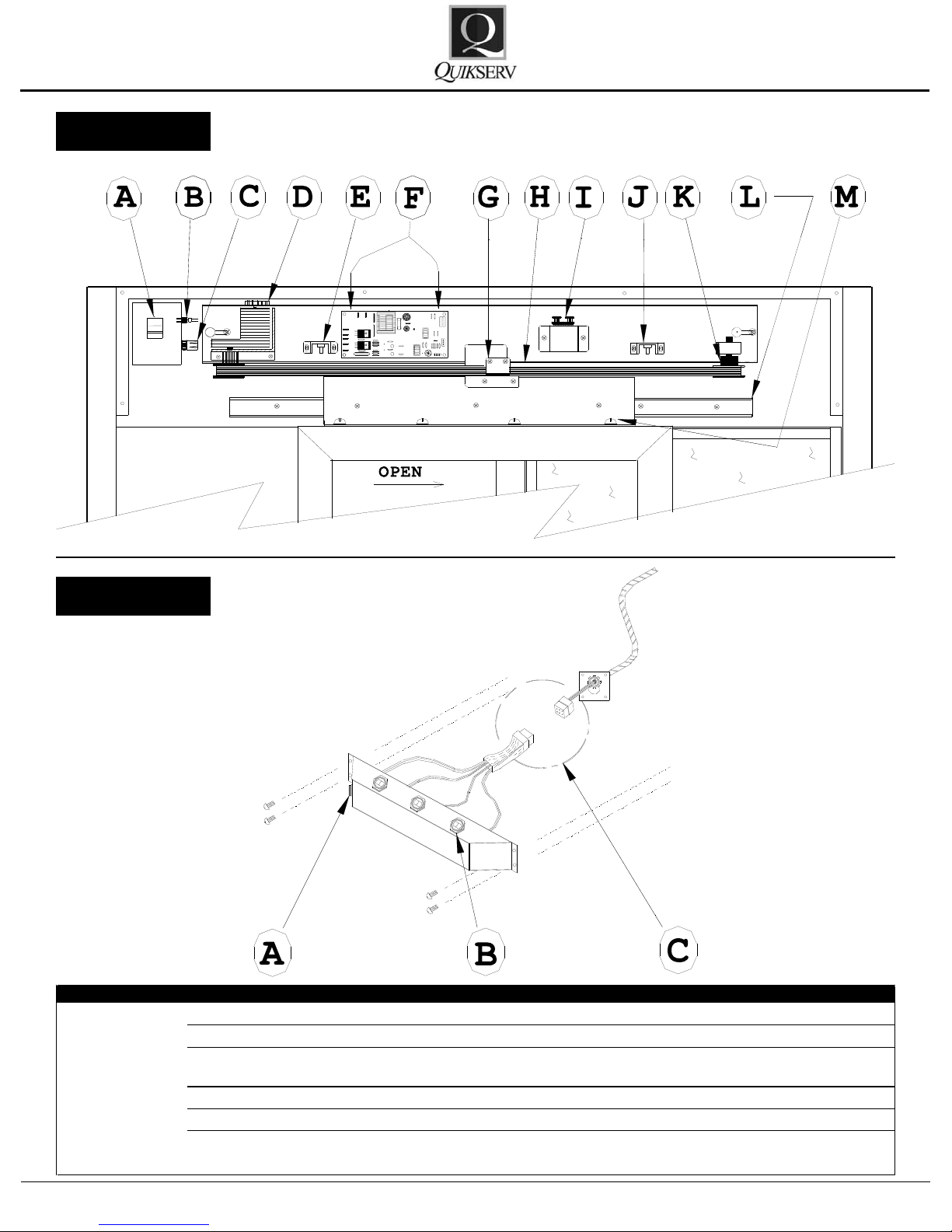
• Turn the Power Switch to the “on” position,
located on the upper left hand corner.
• Proper operation of the “Up-Eye” unit requires
the attendant to be directly in front of and
over all 3 photoelectric sensors while serv-
ing. Proper operation of the “Thru-Beam” unit
requires the attendant to stand between the
Emitter and Receiver eyes.
• <Note> The outside edge of the photo-bar
should be lined up with the outside edge of
the locking jamb.
General Cleaning Guidelines:
• All weather-stripping should be checked and
cleaned weekly.
• All glass, aluminum framing, stainless steel,
and plastic eye covers & lens should be kept
clean at all times. All cleaning uids and ap-
plicators should be non-abrasive.
General Maintenance:
• Slide rail system should be kept clean and re-
oiled with lightweight oil every six (6) months.
• The hook lock and thumb turn should be
cleaned of any grease or grime build up every
six (6) months.
• The eye covers, whether “Up-Eye” or “Thru-
Beam, should be cleaned of any dirt or debris
daily with a non-abrasive cleaner.
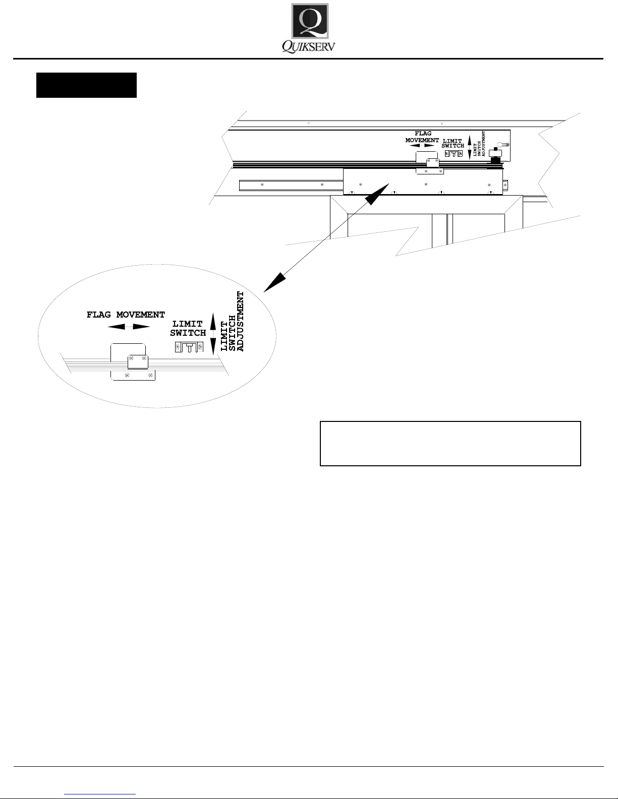
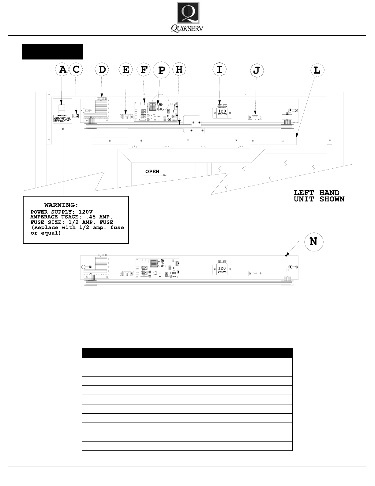
To gain access to the internal compo-
nents for each window, the access panel
must be removed.
Service Manual SST-4035E
2
Quikserv Corp.©quikserv.com • 1-800-388-8307 • Fax (713) 849-5708
Automatic Slider
Operation and Maintenance Procedures
Warning
For your own safety, turn
power switch OFF before
removing the access
panel.

To remove the component rack assembly - see
Figure 2:
1. Unplug power cord from the internal outlet.
2. Remove the lower 5-pin connector.
3. Disconnecttheagbracket(s)fromthedoor
bracket.
4. Loosen the two (2) 7/16” nuts at each end of
the component rack.
5. Remove component rack assembly by sliding
rack to the right and lifting out.
Please refer to the TROUBLE SHOOTING
CHARTS (pg. 5-7) in this manual for additional
information on the window adjustments or ser-
vice procedures.
Contact us at (800) 388-8307 for assistance or
for information on the nearest service center in
your area.
Figure 2
CAUTION: Power Supply = 120 V
Warning: For your own safety, turn power
switch OFF before removing access panel
Service Manual SST-4035E
3
Quikserv Corp.©quikserv.com • 1-800-388-8307 • Fax (713) 849-5708
Component Rack Assembly

The location of the limit switch can be adjusted by
loosening the two (2) screws in the bracket and by
moving the bracket up or down in the adjustment
holes. When set properly the switch should clear
the ag by approximately 1/16”. When the ag
is positioned within the switch, the red LED door
travel light on the PC Board should be OFF.
Note: One of the red LED lights on the PC Board
should only be “ON” when the door or doors are
moving.
Figure 3
Warning: For your own safety, turn power
switch OFF before removing access panel
Service Manual SST-4035E
4
Quikserv Corp.©quikserv.com • 1-800-388-8307 • Fax (713) 849-5708
Limit Switch and Door Flag Adjustment

Trouble Probable Cause Probable Solution
1. Motor shaft pulley or block pulley is loose Tighten pulley or replace (Fig. 4-D (bottom of
motor
)
& K
)
2. Broken drive belt Replace the defective part (Fig. 4-H)
Motor runs, but
the door does
not operate
3.Door bracket disconnected from the drive belt Connect the door bracket to the drive belt (Fig. 4-
G
)
Trouble Probable Cause Probable Solution
1. No power to the unit Check the circuit breaker
2. Power Switch is off or defective Turn on switch or replace (Fig. 4-A)
3. Fuse in switch or PC Board Blown Check and replace (Fig. 4-C or 5-B)
4. Component Rack no plugged in Check and plug in (Fig. 4-B)
5. Open Limit Switch defective or disconnected Replace or reconnect (Fig. 4-E & J)
6. Defective Eye Set Replace defective part (Fig. 9-A) (Pg. 11)
7. Obstruction in the door movement Check locks, slide rail, and remove obstructions
8. Defective motor or capacitor Replace defective part (Fig. 4-D & I)
9. Thermal overload tripped in motor
Caused by obstruction or strain to the motor -
check for obstruction or adjust the limit switch (Fig.
4-E & J
)
10. Defective PC Board Replace (Fig. 4 -F)
Trouble Probable Cause Probable Solution
1. Close limits switch is defective or disconnected Replace or reconnect (Fig. 4-e)
2. Eye assembly is unplugged or disconnected Check connection points and connect (Fig. 6-C)
Remove Obstructions
4. Faulty wire connection Check all connections - repair or replace
5. Defective PC Board Replace (Fig. 4-f)
6. Handicap button pushed in or the switch is defective
Trouble Probable Cause Probable Solution
1. Motor shaft pulley or block pulley is loose Tighten pulley or replace
2. Broken drive belt Replace the defective part
Trouble Probable Cause Probable Solution
1. Thermal overload in the motor has been tripped
Trouble Probable Cause Probable Solution
Clean and oil or tighten (Fig. 4-L)
2. Door bracket loose Tighten screws (Fig. 4-M)
Limit switch or switches may not be set properly
(Fig. 3) & (Fig. 4-E & J) - clear obstructions that
may inhibit the door movement - if power is on;
ensure that the door or doors are unlocked.
Motor will run for
a short period
then sto
p
s:
Doors are
dragging or
bindin
g
1. Slide rail has dirt or debris build-up or the rail is
loose
Motor runs, but
the door does
not operate 3.Door bracket disconnected from the drive belt Connect the door bracket to the drive belt (Fig. 4-
G
)
Window Does
Not Operate
Door or doors
stay in the open
position 3. Photo-eye is obstructed by a person or some
other object
Push switch to the off position or replace (Fig. 6-
A). Not Applicable on serial no.'s above 35,700
Left Hand Unit Shown
Figure 4
Figure 5
Service Manual SST-4035E
5
Quikserv Corp.©quikserv.com • 1-800-388-8307 • Fax (713) 849-5708

Trouble Probable Cause Probable Solution
1. Close limits switch is defective or disconnected Replace or reconnect (Fig. 4-e)
2. Eye assembly is unplugged or disconnected Check connection points and connect (Fig. 6-C)
Remove Obstructions
4. Faulty wire connection Check all connections - repair or replace
5. Defective PC Board Replace (Fig. 4-f)
6. Handicap button pushed in or the switch is defective
Door or doors
stay in the open
position 3. Photo-eye is obstructed by a person or some
other object
Push switch to the off position or replace (Fig. 6-
A). Not Applicable on serial no.'s above 35,700
Left Hand Unit Shown
Figure 4
Figure 6
Service Manual SST-4035E
6
Quikserv Corp.©quikserv.com • 1-800-388-8307 • Fax (713) 849-5708

Trouble Probable Cause Probable Solution
Clean and oil or tighten (Fig. 4-L)
2. Door bracket loose Tighten screws (Fig. 4-M)
Doors are
dragging or
bindin
g
1. Slide rail has dirt or debris build-up or the rail is
loose
Trouble Probable Cause Probable Solution
1. No power to the unit Check the circuit breaker
2. Power Switch is off or defective Turn on switch or replace (Fig. 4-A)
3. Fuse in switch or PC Board Blown Check and replace (Fig. 4-C or 5-B)
4. Component Rack no plugged in Check and plug in (Fig. 4-B)
5. Open Limit Switch defective or disconnected Replace or reconnect (Fig. 4-E & J)
6. Defective Eye Set Replace defective part (Fig. 9-A) (Pg. 11)
7. Obstruction in the door movement Check locks, slide rail, and remove obstructions
8. Defective motor or capacitor Replace defective part (Fig. 4-D & I)
9. Thermal overload tripped in motor
Caused by obstruction or strain to the motor -
check for obstruction or adjust the limit switch (Fig.
4-E & J
)
10. Defective PC Board Replace (Fig. 4 -F)
Trouble Probable Cause Probable Solution
1. Close limits switch is defective or disconnected Replace or reconnect (Fig. 4-e)
2. Eye assembly is unplugged or disconnected Check connection points and connect (Fig. 6-C)
Remove Obstructions
4. Faulty wire connection Check all connections - repair or replace
5. Defective PC Board Replace (Fig. 4-f)
6. Handicap button pushed in or the switch is defective
Trouble Probable Cause Probable Solution
1. Motor shaft pulley or block pulley is loose Tighten pulley or replace
2. Broken drive belt Replace the defective part
Trouble Probable Cause Probable Solution
1. Thermal overload in the motor has been tripped
Trouble Probable Cause Probable Solution
Clean and oil or tighten (Fig. 4-L)
2. Door bracket loose Tighten screws (Fig. 4-M)
Limit switch or switches may not be set properly
(Fig. 3) & (Fig. 4-E & J) - clear obstructions that
may inhibit the door movement - if power is on;
ensure that the door or doors are unlocked.
Motor will run for
a short period
then sto
p
s:
Doors are
dragging or
bindin
g
1. Slide rail has dirt or debris build-up or the rail is
loose
Motor runs, but
the door does
not operate 3.Door bracket disconnected from the drive belt Connect the door bracket to the drive belt (Fig. 4-
G
)
Window Does
Not Operate
Door or doors
stay in the open
position 3. Photo-eye is obstructed by a person or some
other object
Push switch to the off position or replace (Fig. 6-
A). Not Applicable on serial no.'s above 35,700
Left Hand Unit Shown
Figure 4
Figure 3
Service Manual SST-4035E
7
Quikserv Corp.©quikserv.com • 1-800-388-8307 • Fax (713) 849-5708

Figure 7
Service Manual SST-4035E
8
Quikserv Corp.©quikserv.com • 1-800-388-8307 • Fax (713) 849-5708
Electrical Component Layout

Figure 7 A
Service Manual SST-4035E
9
Quikserv Corp.©quikserv.com • 1-800-388-8307 • Fax (713) 849-5708
Electrical Component Layout After Serial No. 38600

Key No. Part No. Description
A 4413 On/Off Switch
C 4425 1/2A 250V in line fuse
D 5615 Drive Motor Assembly
E/J 4451 Limit Switch (2)
F 4460 P.C. Board
H 1052 Drive Belt
I 4401 Capacitor
L 1917 Slide
N 5548 Complete Component Rack
P 4430 500MA 250V P.C. Board Fuse
Figure 8
Service Manual SST-4035E
10
Quikserv Corp.©quikserv.com • 1-800-388-8307 • Fax (713) 849-5708
Replacement Parts for Single Sliding Door

Key No. Part No. Description
A 5602 Thru-Beam Eye Set Assembly
A 5604 Photo-Electric Up-Eye Set
Assembl
y (
Shown Above
)
Key No. Part No. Description
B 4414 Open / Close Switch
C 5323 Protective Plastic Ring
D 4403 Set of Thru-Beam Eyes
D 4404 Set of Up-Eyes
Figure 9
Service Manual SST-4035E
11
Quikserv Corp.©quikserv.com • 1-800-388-8307 • Fax (713) 849-5708
Important
Wire connection must be made as shown.
Failure to make the correct connection
could result in eye set damage or improper
operation.
Warning
For your own safety, turn
power switch OFF before
removing the access
panel.
Eye Set Hookup

1. Quikserv Corp. MUST be notied of a war-
ranty situation before any work is performed.
Otherwise, Quikserv Corp will not be respon-
sible to pay for unauthorized work.
2. Quikserv Corp. requires the following on each
invoice submitted: an itemized account of work
performed detailing hours charged and parts
used, along with a short detailed description
of the problem noted.
3. Quikserv Corp. will authorize a set dollar
amount to be invoiced prior to performing ser-
vices that will be rendered. This amount will
be determined from the initial call to the ser-
vice company as a fair maximum. If additional
amounts are to be invoiced, they must be dis-
cussed with Quikserv Corp. prior to invoicing.
4. A service technician on a warranty service call
needs to call our customer service department
at (800) 388-8307 or (713) 849-5882 before
leaving the job site.
5. A service company representative needs to
call the store where the work is to be per-
formed prior to going to that store. Set up a
date and approximate time of arrival and if it
is foreseen that the agreed upon time cannot
be met, contact the store and make other ar-
rangements.
6. Warranty parts sent to service companies are
parts previously decided on that should cover
the necessary repairs. Additional parts will be
sentuponnoticationtoQuikservCorp.
7. QuikservCorp.needstobenotiedofanyex-
tra parts - either to be sent back or to be kept
by the service technician. Any parts that were
replaced must be returned to Quikserv Corp.
if required verbally or on the service work or-
der copy supplied with the parts sent by Qui-
kserv Corp. If the parts are not returned, the
part cost + mark up will be deducted from the
service invoice.
8. A purchase order number will be given either
verbally or on the service work order from
Quikserv Corp. Please use this on all invoic-
ing.
9. Work required on a window unit not covered
under Quikserv’s warranty must be reported
to Quikserv Corp. before work is begun.
10.Quikserv’s payment terms are net 30. The in-
formation above will help us assure the fast-
est and most efcient service possible. For
further information or if you have any ques-
tions, please do not hesitate to contact us at
(800) 388-8307.
Customer Service Department
Warranty Service Policy
Service Manual SST-4035E
12
Quikserv Corp.©quikserv.com • 1-800-388-8307 • Fax (713) 849-5708
Table of contents
Popular Indoor Furnishing manuals by other brands

Trendteam
Trendteam BLANSHE 2122-308-C9 installation instructions

IKEA
IKEA LACKO 201.518.37 manual

Venjakob
Venjakob 655 Series Assembly instructions

VIPACK
VIPACK AMORI AMBU1314 Assembly instructions

Naterial
Naterial ORIS Alu 3276007267815 Assemby - Use - Maintenance Manual

Habitat
Habitat Lecco 986889 manual

Kitchen Cabinet Kings
Kitchen Cabinet Kings B09 Assembly guide

Homelegance
Homelegance 1555K-1 Service manual

BCP
BCP SKY5429 instruction manual

Strictly Beds & Bunks
Strictly Beds & Bunks ATHENS BED FRAME Assembly instructions

Mocka
Mocka Eliza Buffet Assembly instructions

aspenhome
aspenhome I222-422 Assembly instructions