Page 8
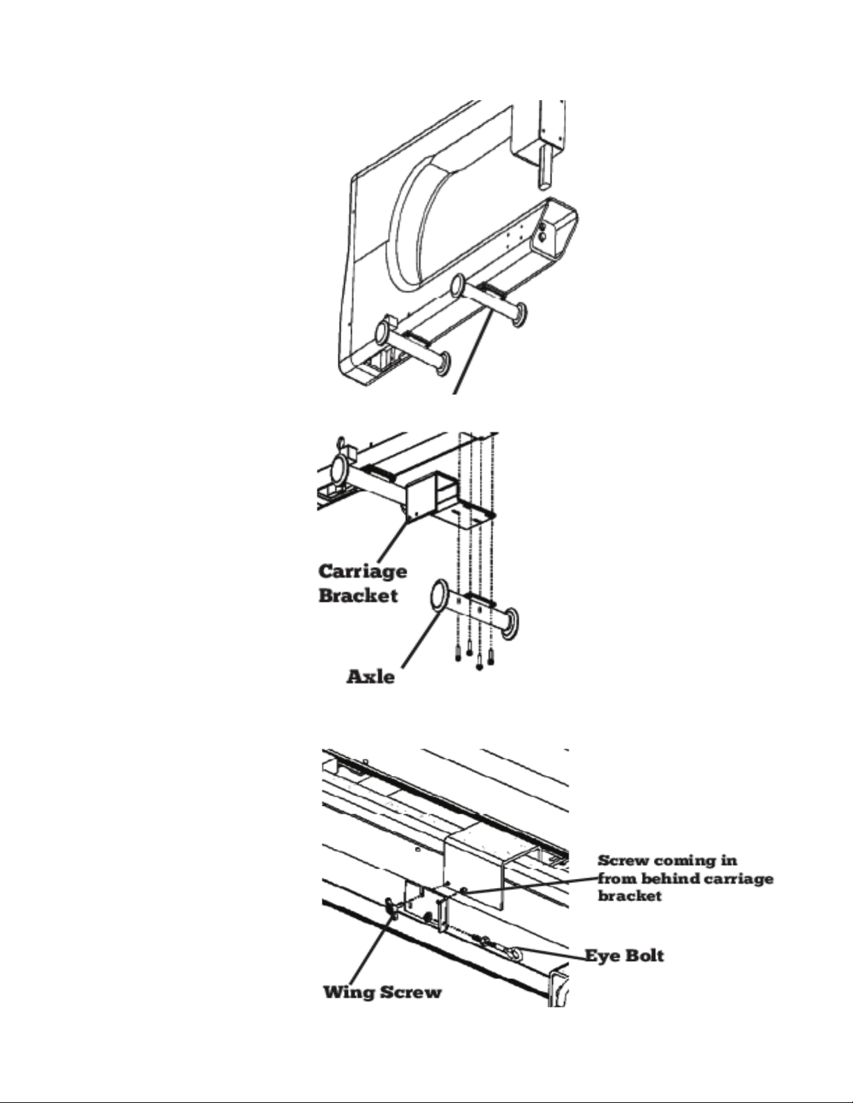
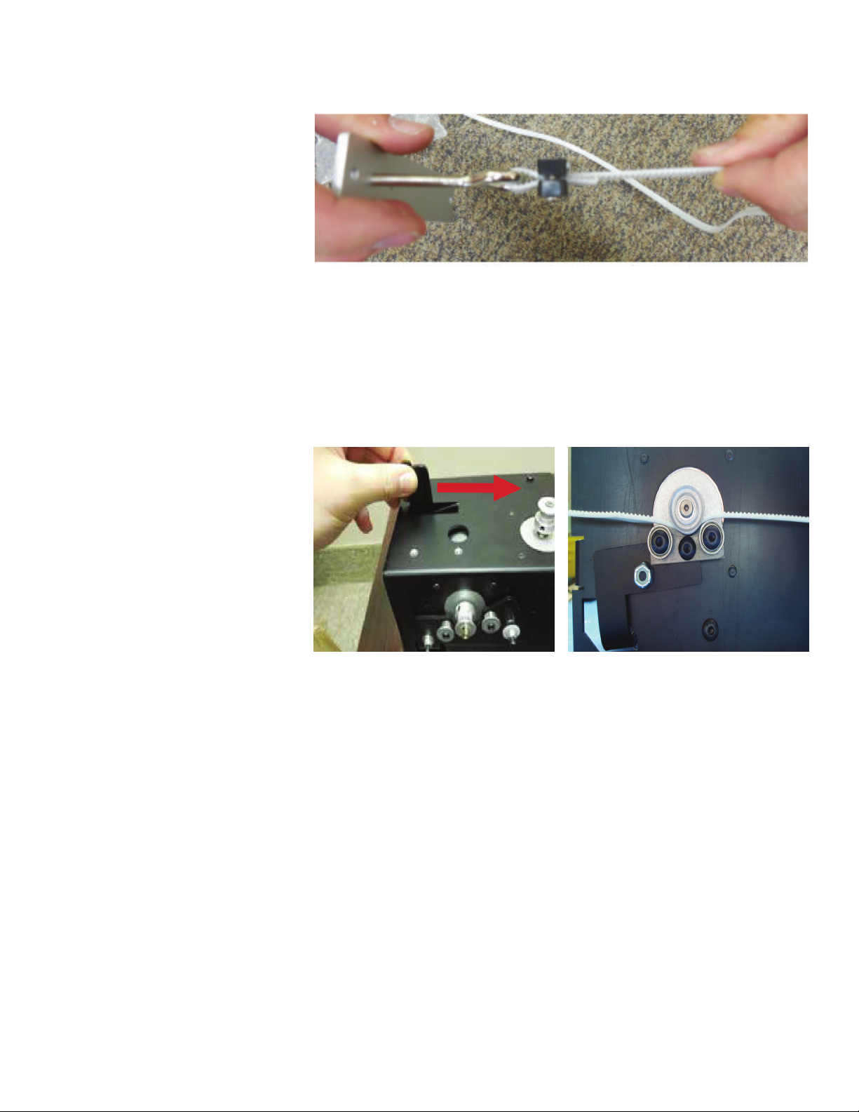
4Attach the remaining end
of the belt to the to the
eye bolt with a belt clamp.
Tighten the eye bolt as
needed to tighten the
belt. It should have some
play, but not a lot.
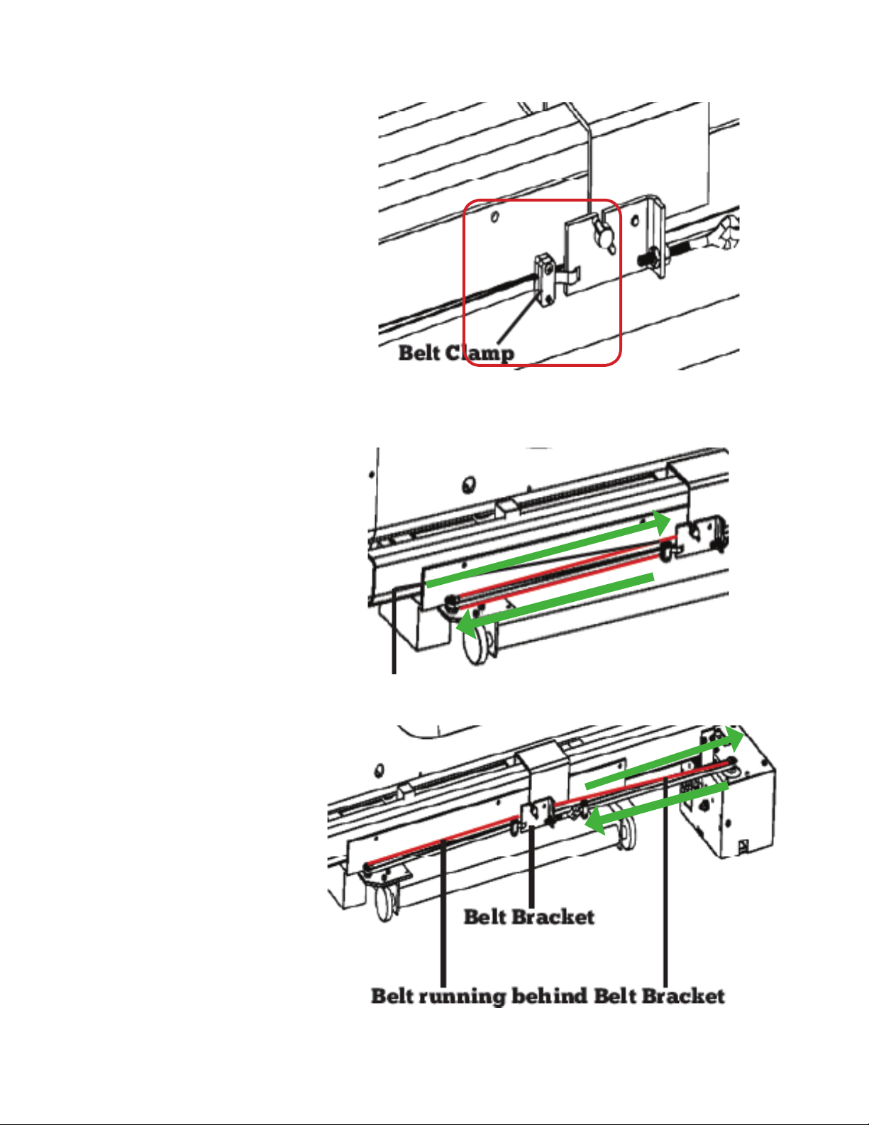
Install the White Belt (Bag X10 and Bag X1)
1ere are many dierent
options to mount the
clamp brackets to the
frame.
e brackets must be
mounted in a way that
the eye bolts are in line
with the x-axis pulley on
the motor.
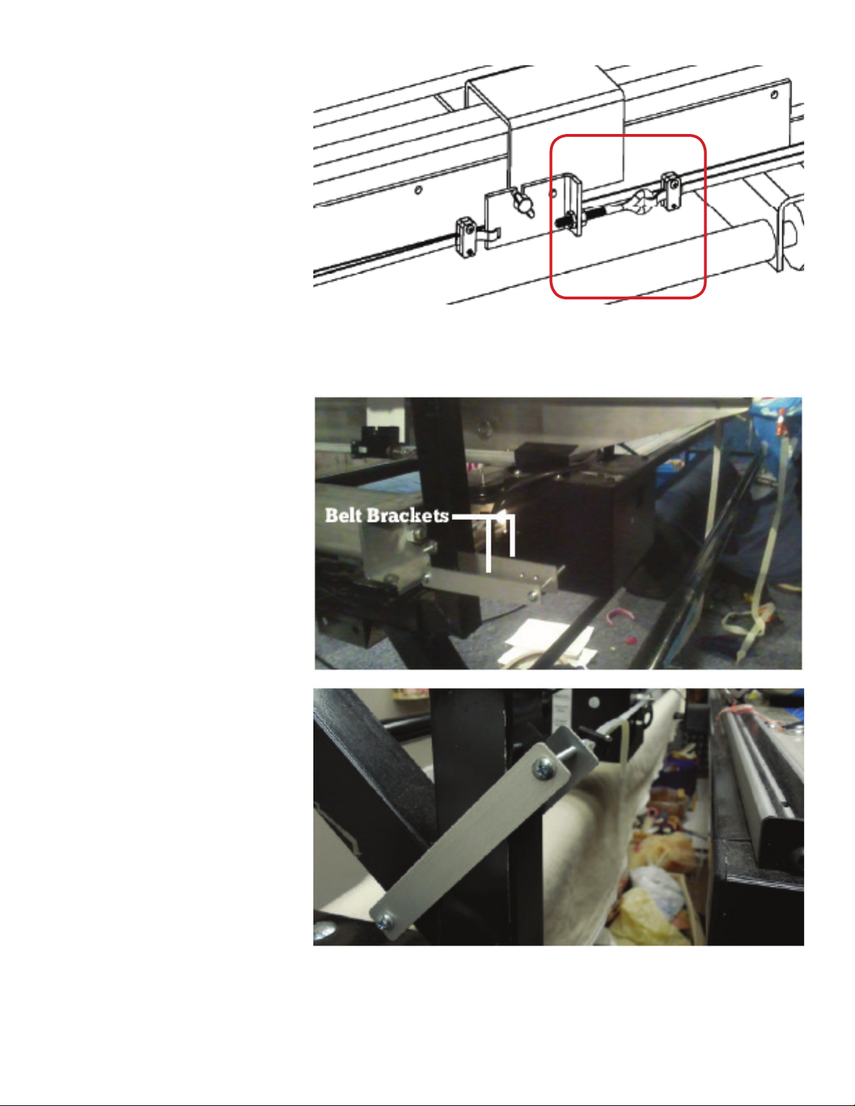
Displayed are two
options for mounting, but
options are not limited to
these two.