QUNDIS RNN5 User manual

Netzwerkknoten RNN5
Network node
cz Návod k obsluze a instalaci
de Bedienungs- und Installationsanleitung
en Operating and Installation Instructions
fr Notice d‘utilisation et d‘installation
it Istruzioni uso/installazione
sl Navodila za upravljanje
tr Kullanım-kurulum talimatı
node 5

de
2 FOM5-00AM-DES-RNN5 V1.0 / 10.03.2015
cs Česky....................................................................................................................................3
de Deutsch ................................................................................................................................8
en English................................................................................................................................13
fr Français..............................................................................................................................18
it Italiano................................................................................................................................23
sl Slovenščina........................................................................................................................28
tr Türkçe.................................................................................................................................33
Dimensions ..............................................................................................................................38
Certificates...............................................................................................................................39

cs - Návod k obsluze a instalaci Qnode5
Návod k obsluze a instalaci Qnode5 - cs
V1.0 / 10.03.2015 FOM5-00AM-DES-RNN5
3
Výměna lithiových baterií:
Baterie smí vyměňovat pouze kvalikovaný personál. Pro zaručení
montáže se správnou polaritou lze připojovací konektor připojit
pouze v jedné poloze. Proto se při zastrčení nesmí vyvíjet žádná
nadměrná síla.
Pozor: Nebezpečí exploze při neodborné výměně bate-
rií. Výměnu proveďte pouze za ten samý nebo výrobcem
doporučený rovnocenný typ.
Likvidace: Lithiové baterie nepatří do domovního odpadu! Použité
baterie odevzdejte v příslušné sběrně nebezpečného odpadu. Při
likvidaci se musí respektovat místní a specické státní předpisy!
Ochrana před bleskem
Pokud je ve větších zařízeních vytvořena celková síť z jednotlivých
sítí pomocí sběrnice M-Bus, musí se, pokud jsou sběrnicová vedení
položena vně budovy, opatřit ochranou před bleskem.
Kvalikovaný personál
Při nekvalikovaných zásazích do přístroje / systému, manipulacích
nebo nerespektování výstražných upozornění v tomto návodu může
dojít k těžkým tělesným zraněním nebo věcným škodám. Zásahy do
přístroje / systému smí proto provádět pouze příslušně kvalikovaný
personál.
Důležité upozornění
Tento výrobek je třeba nainstalovat odborně a podle zadaných
montážních směrnic, a proto ho smí montovat pouze kvalikovaný a
vyškolený odborný personál! Pro instalaci ve stavebních objektech
se zvýšenými požadavky požární ochrany, např. schodiště, únikové
cesty, musí montážní provoz popř. odborný personál dbát na to, aby
byly dodrženy specické požadavky stavebního práva země užití!
Použití v souladu s určením
Bateriemi napájené síťové uzly slouží k ukládání a přenosu dat
spotřeby z příslušných vhodných měřicích přístrojů. Síťové uzly jsou
určeny výhradně na tento účel.
Použití v rozporu s určením
Jiné použití, než je výše popsané, nebo úprava přístroje se považuje
za použití v rozporu s určením, před jejichž realizací je potřebná
písemná žádost a speciální schválení.
Ručení a záruka
Nároky vyplývající z ručení a záruky lze uplatňovat pouze tehdy, po-
kud se díly používaly v souladu s určením a byly dodrženy technické
podmínky a platné technické předpisy.
Bezpečnostní upozornění
Respektujte technické normy pro elektrické připojení a související
platné národní předpisy.
Respektujte technické normy pro elektrické připojení datových
komunikačních modulů a související platné národní předpisy.
Tento návod musí být uschován po celou
dobu životnosti Q node 5
Použité symboly
CE označení
Přístroj odpovídá platným specickým ev-
ropským směrnicím!
Ochranné malé napětí
Přístroj odpovídá třídě ochrany III.
Konstrukční prvky ohrožené elektrostatický-
mi výboji (ESD)
Přístroj obsahuje konstrukční prvky, které mohou být
poškozeny elektrostatickými výboji.
Pozor
Symbol upozorňuje na možná
nebezpečí nebo věcné škody.
Provoz pouze v uzavřených prostorech
Přístroj se smí používat pouze v uzavřených pros-
torech.
Nebezpečné zboží
Bateriemi napájené síťové uzly Q node 5 ob-
sahují lithiové články, pro které platí přepravní
omezení (ADR třída 9).
Bezpečnostní upozornění
pro lithiové baterie
Pokyny pro nouzové situace při nehodách
s lithiovými bateriemi
Všechny síťové uzly typu Q node 5 jsou napájeny jednou lithio-
vou baterií SAFT LSH20 a jsou vybaveny lithiovou záložní baterií
typu SAFT LS 14500 AA. Tyto typy baterií jsou klasikovány jako
nebezpečné zboží.
MUSÍ SE DODRŽOVAT AKTUÁLNĚ PLATNÉ PŘEDPISY PRO
PŘEPRAVU!
Atest pro používané baterie získáte na vyžádání.
Zacházení s lithiovými bateriemi:
• skladujte chráněné před vlhkostí
• neskladujte v dosahu dětí
• nezahřívejte nad teplotu 100 °C nebo nevhazujte do ohně
• nezkratujte
• neotvírejte nebo nepoškozujte
• nenabíjejte
V nouzových situacích se musí respektovat následující pokyny:
Při vytečení:
• pokryjte uhličitanem sodným nebo krystalickou sodou
• plyny, výpary srazte rozprášením vody
• zajistěte dostatečné větrání
• vyhněte se jakémukoliv přímému kontaktu
Při poranění:
• Pokud vnitřní složky suchého článku přijdou do styku s očima,
vypláchněte je okamžitě 15 minut vodou.
• Při kontaktu s pokožkou opláchněte zasažené místo velkým
množstvím vody a znečištěný oděv odložte.
• Po vdechnutí opusťte místo nehody.
• V každém případě musíte vyhledat lékaře!
Při požáru:
• Použijte hasicí přístroj Lith-X nebo třídy D!
• V ŽÁDNÉM PŘÍPADĚ NEHASTE VODOU!
• Nepoužívejte hasicí přístroje s CO2, halogenové hasicí přístroje, ha-
sicí přístroje se suchými substancemi nebo pěnové hasicí přístroje!
• Po vdechnutí opusťte místo nehody a vyvětrejte.
• V každém případě musíte vyhledat lékaře.
Další informace na telefonním čísle +49 (0) 69-509530; ID 11057

cs - Návod k obsluze a instalaci Qnode5
Návod k obsluze a instalaci Qnode5 - cs
4 FOM5-00AM-DES-RNN5 V1.0 / 10.03.2015
Technický popis
Síťové uzly Q node 5 přijímají a zpracovávají data z měřičů spotřeby (maximálně 500) v rámci systému Q AMR. Více síťových uzlů (maximálně
dvanáct) tvoří síť. Pro různé případy použití existují různé typy síťových uzlů. Všechny typy lze vzájemně kombinovat do sítě.
Technické údaje Q node 5
CE shoda a směrnice EMC
Krytí IP 20
Třída ochrany III
Elektromagnetická kompatibilita
Odolnost proti rušení:
Rušivé vyzařování
Bezpečnost zařízení v IT
EN 301 489
EN 300 220-1
EM 60950
Jmenovité napětí DC 3,6 V
Životnost
Hlavní baterie (při výrobním nastavení)
Záložní baterie > 5 let
> 10 let
Okolní podmínky
během transportu v nádobách bez ventilace
v nádobách s ventilací
Relativní vlhkost vzduchu
-25…+70 °C
-25…+40°C
max. 95% na 40°C
během uskladnění
Relativní vlhkost vzduchu
-5…+45 °C
max. 95%
během provozu
Relativní vlhkost vzduchu
…+55 °C
max. 95%
Hmotnost brutto
netto
0,760 kg
0,648 kg
Úrovně zobrazení
-Aktuální
provozní režim (Mode)
A
Střídavě číslo Q node 5 (primární
adresa) a číslo sítě
BPočet Q node 5 v síti
CPočet měřičů spotřeby v síti
DZbývající kapacita Q node 5 v pro-
centech
EPoruchové kódy (tři skupiny)
Konstrukční skupiny Q node 5
Síťový uzel Q node 5 se skládá z následujících konstrukčních sku-
pin:
Napájení proudem:
Baterie
Vysílací / Přijímací zaříze-
ní pro Q AMR síť
Paměť
500 měřicích přístrojů
Sběrnice
M-Bus
(Slave)
IrDA
(optický)
Záložní baterie
Vysílací a přijímací zařízení slouží k záznamu dat měřičů spotřeby
a jejich předání dalším síťovým uzlům ve stejné síti. Datová pa-
měť ukládá naměřené hodnoty měřičů spotřeby Záložní baterií je
chráněná proti dočasnému výpadku napájení proudem, například
při výměně hlavní baterie. Pomocí interface sběrnice M-Bus (zátěž
M-Bus) lze realizovat lokální načtení sítí.
Komponenty a ovládací prvky
(1) Konektorová zásuvka pro
servisní přípojku sběrnice
M-Bus
(2) Konektorová zásuvka pro
rozšiřující modul
(3) Konektorová zásuvka pro
napájení DC 3,6 V
(4) LED pro indikaci síťového
napětí při externím napájení
(svítí pouze při napájení sítě)
(5) Konektorová zásuvka pro
záložní baterii DC 3,6 V
(6) Zástrčkový panel
(7) Tlačítko Reset (zapuštěné)
(8) Displej
(9) Sériové číslo
(10) Tlačítko Provozní
režim
(MODE, červené)
(11) Tlačítko přepnutí displeje
(DISPLAY, modré)
(12) Rozhraní IrDA
(optické)
Tlačítka
Síťový uzel má 3 tlačítka s následujícími funkcemi:
DISPLAY Tlačítko (10) k přepnutí displeje a potvrzení poruch.
MODE Tlačítko (9) k zapnutí a vypnutí instalačního režimu. Je-li aktivní rozšířený režim, přepíná se tímto tlačítkem zpět do standardního
režimu.
RESET Zapuštěné tlačítko (7) k spuštění resetu sítě (přerušení všech spojení mezi síťovými uzly).

cs - Návod k obsluze a instalaci Qnode5
Návod k obsluze a instalaci Qnode5 - cs
V1.0 / 10.03.2015 FOM5-00AM-DES-RNN5
5
Provozní režimy a stavy systému
Existují různé provozní režimy, které se nastavují zčásti stiskem tla-
čítka na síťovém uzlu, zčásti automaticky nebo z připojeného PC
pomocí software pro uvedení do provozu ACT26. K tomu musí být
k dispozici software pro uvedení do provozu ACT26 v aktuální verzi.
Příslušný provozní režim je zobrazen na displeji:
Provozní
režim Displej Poznámka
Idle-mode V tomto režimu je síťový uzel neaktivní.
Dlouhým stisknutím tlačítka MODE (>2
sec.) přechází do instalačního režimu.
Standardní
režim Toto je normální provozní režim sbě-
račů dat: Jsou přijímány a ukládány
telegramy registrovaných měřicích pří-
strojů a dále předávány v síti.
Rozšířený
standardní
režim1)
M
Přijímací zařízení je stále aktivní a
umožňuje tak rychlou komunikaci. Ten-
to režim se spouští manuálně servis-
ním nástrojem ACT26.
Instalační
režim2)
V instalačním režimu je automaticky
vybudována rádiová síť. Měřicí přístro-
je, vysílající během tohoto provozního
režimu instalační telegramy, jsou v síti
zaregistrovány. Tento režim se spouští
dlouhým stisknutím (>2 sec.) tlačítka
MODE.
Rozšířený
instalační
režim2)
M
Rozšířený instalační režim registruje
všechny měřicí přístroje, vysílající in-
stalační nebo datové telegramy. Tento
režim pomáhá, pokud byla síť vytvoře-
na dodatečně. Nedochází k vytvoření
sítě!
Chráněný
instalační
režim2)
Jako instalační režim, ale je vytvořeno
pouze propojení k přístrojům, používa-
jícím stejné síťové označení.
Vyhledáva-
cí režim Měřicí přístroje, které byly zaneseny
manuálně nebo ztratily rádiové spoje-
ní, jsou opět synchronizovány. Tento
režim je aktivován automaticky.
Rozšířený
vyhledáva-
cí režim2)
M
Toto vyhledávání se používá k obnově
ztraceného rádiového spojení nebo
manuálně zanesených měřicích pří-
strojů. Tento režim lze spustit i manu-
álně při nastaveném jumperu 1 (v zá-
strčkovém panelu) a dlouhém stisknutí
tlačítka MODE!
Režim
vymazání2)
Jako instalační režim, ale všechny re-
gistrované přístroje, vysílající instalační
telegramy, nejsou registrovány ale vy-
mazány (výměna počítadla)!
Stav
systému Displej Poznámka
Dálkový
přístup
C
Je-li ze zařízení Master realizován
přístup k síťovým uzlům, zobrazí se
symbol „ɔ“.
Režim
Highspeed
například
M
Pokud mají všechny síťové uzly svá
přijímací zařízení stále zapnutá, takže
dochází v rámci sítě k okamžité výmě-
ně všech dat, je to zobrazeno dvěma
body v horní části LCD displeje.
Sběrnicové
spojení
například Je-li vytvořeno spojení se sběrnicí, je
na této sběrnici provedeno krátkodobě
zobrazení čísla sběrnice (0=sběrnice
M-Bus) a nastavené primární adresy.
V příkladu byl síťový uzel s primární
adresou 03 spojen s M-sběrnicí!
Režim Ir-
DA-Master
Tento režim se spouští krátkým stisk-
nutím (<0,5 sec.) tlačítka MODE. Sig-
nalizuje, že mohou být nyní spojeny
další IrDA přístroje (v režimu IrDA-Sla-
ve). Tento režim je po 10 sec nečinnosti
automaticky ukončen.
Vložit například Je-li v režimu IrDA-Master propojen
neregistrovaný IrDA vhodný měřicí
přístroj např. WHE467, lze jej do sí-
ťového uzlu vložit. Indikace odpovídá
posledním 4 místům měřicího přístroje
(příklad: 20000123). Pro potvrzení se
musí během této indikace stisknout tla-
čítko DISPLAY. Potom je přístroj zare-
gistrován a spuštěn vyhledávací režim.
Vymazat například Je-li v režimu IrDA-Master propojen již
registrovaný IrDA vhodný měřicí pří-
stroj, lze jej ze síťového uzlu odstranit
Indikace odpovídá posledním 4 místům
měřicího přístroje (příklad: 20000123).
Pro potvrzení se musí během této in-
dikace stisknout tlačítko DISPLAY. Po-
tom je přístroj vymazán a vyhledávací
režim eventuálně ukončen.
Kopírovat například Je-li v režimu IrDA-Master připojen
nový síťový uzel (v režimu IdLe!), lze
do nového uzlu nakopírovat všechna
síťová data. Pro potvrzení se musí
během této indikace stisknout tlačítko
DISPLAY. V síti se automaticky spustí
chráněný instalační režim.
Kopírování trvá v závislosti na obsahu
dat až 20 min. Na závěr je na displeji
nového uzlu po dobu 1 hod. zobrazeno
„StArt Prot“. Po montáži se tlačítkem
DISPLAY spustí chráněný instalační
režim i na novém síťovém uzlu. Uzel je
integrován v síti a spustí se automatic-
ky vyhledávací režim
1) je u bateriemi napájených síťových uzlů automaticky ukončen po cca. 8 hod.
2) je automaticky ukončen po cca. 8 hod.

cs - Návod k obsluze a instalaci Qnode5
Návod k obsluze a instalaci Qnode5 - cs
6 FOM5-00AM-DES-RNN5 V1.0 / 10.03.2015
Poruchové kódy
Značka ‚x’ v ‚b‘ a ‚C‘ popisuje, jak často se porucha vyskytla. Pokus
se porucha jedné skupiny vyskytne častěji než 9 mal, je zde zobra-
zena čárka ‚-‘.
Přístroj samotný
EA10 Všeobecná porucha přístroje
EA11 Porucha hardware
EA12 Porucha paměti / Ztráta dat
EA20 Parametr mimo mez tolerance
EA21 Hlavní baterie slabá
EA22 Záložní baterie slabá
EA30 Porucha tolerance jiného systémového přístroje
EA31 Primární konikt adres (adresa zadána dvakrát)
EA38 Porucha hodin
Jiné síťové uzly
Eb1x Porucha přístroje (hardware nebo paměť)
Eb2x Baterie příliš slabá nebo přístroj mimo toleranci
Eb3x Vyskytla se porucha 1 a 2
Eb4x Komunikace se síťovými uzly přerušena
Eb5x Vyskytla se porucha 1 a 4
Eb6x Vyskytla se porucha 2 a 4
Eb7x Vyskytla se porucha 1, 2 a 4
Měřicí přístroje
EC1x Porucha přístroje (hardware nebo paměť)
EC2x Baterie příliš slabá nebo přístroj mimo toleranci
EC3x Vyskytla se porucha 1 a 2
EC4x Komunikace s měřicími přístroji přerušena
EC5x Vyskytla se porucha 1 a 4
EC6x Vyskytla se porucha 2 a 4
EC7x Vyskytla se porucha 1, 2 a 4
Režim IrDA Master
Err1 Přístroj nepodporován!
Err2 Přístroj neakceptován,
- seznamy jsou plné např. více než 500 měřicích
přístrojů
- cizí přístroj poskytuje chybná data nebo porucha
Err3 Autorizace se nezdařila!
- cizí přístroj očekává správný Login a heslo!
Err4 Přerušení komunikace!
- Přerušení spojení před koncem komunikace
Err5 Chybná kongurace!
- Uzel ještě v Idle režimu
- Adaptér pulzů není parametrizován
- cizí síťové uzly nejsou v Idle režimu
Potvrzení poruch
Poté co je porucha vzata na vědomí, lze hlášení poruchy potvrzením
vymazat. K tomu se opakovaným stisknutím modrého tlačítka DIS-
PLAY přejde do úrovně zobrazení „E“. Pokud se potom tlačítko DIS-
PLAY stiskne na dalších více než dvě vteřiny, vymažou se všechny
poruchy úrovně „EA“. Dojde-li opět k poruchovému stavu objeví se
na displeji opět poruchový kód.
Montážní pokyny
Místo montáže
Síťové uzly Q node 5 jsou určeny pouze pro použití uvnitř budov. Ty-
pový štítek je umístěn na vnitřní straně víka tělesa.
Opatření k vyloučení poruch
Síťové uzly instalujte v prostředí chráněném před vlivem mrazu v
bezpečné vzdálenosti od silnoproudých vedení nebo elektrických
zařízení a na nekovovém a nevodivém podkladu (před uvedením
do provozu si přečtěte část 6.4 Stručný popis instalace nv instalační
příručce Q AMR)
Jako lepidlo k přilepení Q node 5 se nesmí použít silikon! Pokud je u
obkládaček apod. použit jako lepidlo silikon, musí se po jeho použití
minimálně 24 hod. vyčkat, než lze Q node 5 namontovat.
Mechanické připevnění Q node 5
Uzel Q node 5 se připevní ke zdi pomocí dvou šroubů. Proto se musí
ve vzdálenosti 184 mm vyvrtat dva otvory o průměru 6 mm. Šrouby
a hmoždinky jsou obsaženy v rozsahu dodávky.
Uvedení do provozu Q node 5
Uzel Q node 5 se z bezpečnost-
ních důvodů dodává s nepřipoje-
nou hlavní baterií.
(1) Konektorová zásuvka pro
napájení DC 3,6 V
(2) Konektorová zásuvka pro
záložní baterii
(3) Hlavní baterie
(4) Záložní baterie
Start výpočtu životnosti při nové baterii:
Po připevnění síťového uzlu se zástrčka baterie zastrčí do příslušné
připojovací zdířky (1). Displej síťového uzlu udává . Obsluha
musí potom pro spuštění výpočtu životnosti pro novou hlavní baterii
jednou stisknout modré tlačítko DISPLAY.
Pozor: V běžném provozu síťového uzlu je možno hlavní baterii
odpojit a potom zástrčku znovu zastrčit. V tomto případě se nesmí
stisknout tlačítko DISPLAY – výsledkem by byl chybný údaj zbýva-
jící kapacity!
Výměna baterie: Pro výměnu vybité hlavní baterie se musí nejprve
stará baterie vyjmout a potom vložit nová baterie. Obsluha musí po-
tom pro spuštění výpočtu životnosti pro novou hlavní baterii jednou
stisknout modré tlačítko DISPLAY.
Záložní baterie se k tomuto okamžiku nesmí odebrat. Mělo by
to za následek ztrátu dat!
Depasivace: Při dlouhém skladování hlavní baterie, zejména při
teplotách skladování více než 30 °C, může dojít k pasivaci bate-
rie. Ta pak není schopná, zásobit síťový uzel okamžitě dostatečnou
energií. Pokud síťový uzel identikuje pasivovanou baterii, spouští
automaticky cyklus depasivace. To je indikované blikající diodou na
přední straně. Tento proces může trvat několik minut. Potom síťový
uzel startuje do režimu IdLE. Při silném podchlazení baterie může
k tomuto chování dojít i později při jiných režimech (např. v insta-
lačním režimu)!

cs - Návod k obsluze a instalaci Qnode5
Návod k obsluze a instalaci Qnode5 - cs
V1.0 / 10.03.2015 FOM5-00AM-DES-RNN5
7
Správná likvidace tohoto výrobku
V Německu a pro výrobky dodávané přímo z Německa
Všechny přístroje se musejí odevzdat k regulované recyk-
laci. Vzhledem k aplikovaným předpisům
se elektrické a elektronické přístroje QUNDIS nesmějí likvidovat
prostřednictvím veřejných sběrných míst pro elektrické přístroje.
Kompletní staré elektronické přístroje QUNDIS je třeba zaslat k lik-
vidaci nám.
Ofrankovaná zásilka se pošle na následující adresu:
QUNDIS GmbH
Sonnentor 2 Tel: +49 (0) 361 26 280-0
99098 Erfurt Fax: +49 (0) 361 26 280-175
Deutschland Mail: [email protected]
QUNDIS zajišťuje řádné rozebrání a recyklaci přístrojů. Náklady za likvidaci jsou QUNDIS.
Alternativně muže být likvidace provedena zákazníkem na základě stanoveného číselníku odpadů, prostřednictvím soukromé rmy
provádějící likvidaci odpadů.
V zemích Evropské unie mimo Německa
Informace pro náležitou likvidaci získáte od vašeho prodejce nebo příslušného odbytu.
Přípojení M-Bus
U každého síťového uzlu lze přechodně nebo trvale (pevná insta-
lace) pomocí konektoru u jedné ze dvou konektorových zásuvek
pro servisní přípojení M-Bus (1) připojit sběrnici M-Bus. Konektor je
součástí rozsahu dodávky.
Zaplombování
Po ukončení uvedení do provozu se musí síťový uzel zajistit doda-
nou plombou. Plomba se vsazuje do plombovacího otvoru na pravé
straně síťového uzlu.
Síťová instalace
U síťového uzlu Q node 5 se stiskne tlačítko MODE. Tlačítko se musí být stisknuté déle než 2 sec. Tímto stisknutím tlačítka přejde síťový uzel
do instalačního režimu (identikovatelné dle indikace na LCD a dle blikající LED diody na přední straně). Tento síťový uzel konguruje
pak automaticky do rádiové sítě všechny později přiřazené síťové uzly, které jsou v instalačním režimu.
Tři síťové uzly před síťovou in-
stalací:
Úroveň zobrazení A udává stří-
davě různé rádiové primární
adresy a čísla sítě (v souladu s
expedičním stavem Q node 5).
Tři síťové uzly po síťové instalací
a během ní:
Úroveň zobrazení A udává běž-
né rádiové primární adresy a
identické číslo sítě.
Před síťovou instalací:
Úroveň zobrazení B udává vždy
jeden síťový uzel
Po síťové instalací a během ní:
Úroveň zobrazení B udává počet
síťových uzlů v síti..
Instalace měřicích přístrojů:
Měřicí přístroje se nastaví do instalačního
režimu:
Stiskněte tlačítko dlouho až do dosažení
úrovně Info, potom je krátce stiskněte až
po zobrazení adresy sběrnice ,
potom je stiskněte dlouze znovu až po zob-
razení
Měřiče nákladů na topení, např. Q caloric 5, se při montáži nastaví
automaticky do instalačního režimu.
Před síťovou instalací:
Úroveň zobrazení C neudává
nyní v síti žádné měřicí přístroje
Po síťové instalací a během ní:
Úroveň zobrazení B udává počet
síťových uzlů v síti..
Ukončení síťové instalace
Na závěr se musí zajistit, aby všechny síťové uzly uložily správný
počet měřicích přístrojů a a síťových uzlů (zkontrolujte úroveň ‚b’ a
‚C’ u posledních síťových uzlů). Pro ukončení instalačního režimu,
se musí u jednoho síťového uzlu stisknout na dvě vteřiny tlačítko
MODE. Na displeji se objeví údaj pro standardní režim . LED
dioda na přední straně může ještě až 30 sec. blikat. V návaznosti
na to jsou všechny uzly v síti nastaveny do standardního režimu.
Sběrnice M-Bus
pevná přípojka
M-Bus přípojka
Gateway a servis

8 FOM5-00AM-DES-RNN5 V1.0 / 10.03.2015
de - Bedienungs- und Installationsanleitung Q node 5
Bedienungs- und Installationsanleitung Q node 5 - de
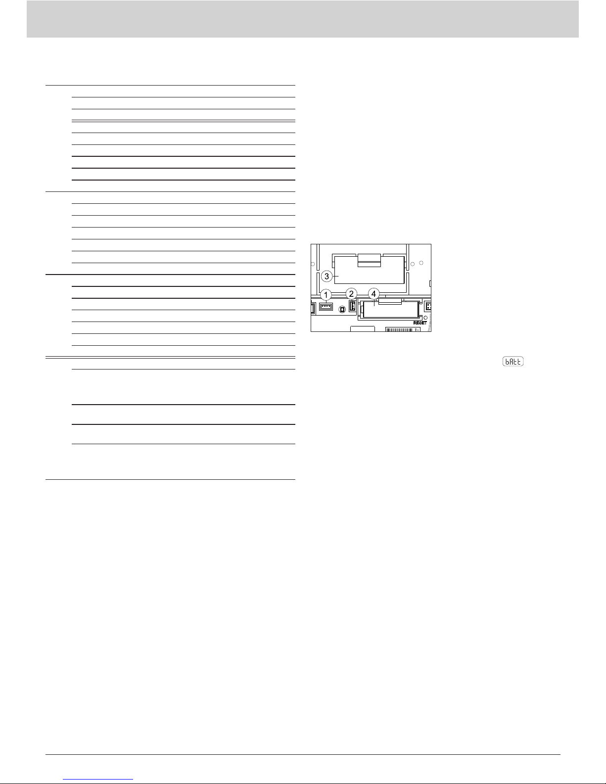
Austausch von Lithiumbatterien:
Batterien dürfen nur von qualiziertem Personal getauscht werden.
Der Anschlussstecker passt nur in einer Stellung, um den polaritäts-
richtigen Einbau zu gewährleisten. Deshalb darf beim Stecken keine
übermäßige Kraft angewendet werden.
Vorsicht: Explosionsgefahr bei unsachgemäßem Aus-
tausch der Batterien. Ersatz nur durch denselben oder
einen vom Hersteller empfohlenen gleichwertigen Typ.
Entsorgung: Lithiumbatterien gehören nicht in den Hausmüll! Füh-
ren Sie gebrauchte Batterien Ihren örtlichen Entsorgungsstellen zu.
Die lokalen und landesspezischen Vorschriften für die Entsorgung
sind zu beachten!
Blitzschutz
Soll in größeren Anlagen aus Einzelnetzwerken über M-Bus ein Ge-
samtnetzwerk gebildet werden, so ist, wenn die Busleitungen außer-
halb des Gebäudes verlegt werden, ein Blitzschutz vorzusehen.
Qualiziertes Personal
Bei unqualizierten Eingriffen in das Gerät / System, Manipulatio-
nen oder Nichtbeachtung der in dieser Anleitung gegebenen Warn-
hinweise können schwere Körperverletzungen oder Sachschäden
eintreten. Nur entsprechend qualiziertes Personal darf deshalb
Eingriffe an diesem Gerät / System vornehmen.
Wichtiger Hinweis
Dieses Produkt ist fachgerecht und nach den vorgegebenen Monta-
gerichtlinien zu installieren und darf daher nur durch ausgebildetes
und geschultes Fachpersonal montiert werden. Für die Installation
in Baukörpern mit erhöhten Brandschutzanforderungen, z.B. Trep-
penhäusern, Fluchtwegen, hat der Einbaubetrieb bzw. das Fachper-
sonal darauf zu achten, dass die nach Landesbaurecht spezischen
Anforderungen eingehalten werden!
Bestimmungsgemäße Verwendung
Die batteriebetriebenen Netzwerkknoten dienen zur Speicherung
und Weiterleitung von Verbrauchsdaten von hierfür geeigneten
Messgeräten. Die Netzwerkknoten sind ausschließlich zu diesem
Zweck bestimmt.
Nicht bestimmungsgemäße Verwendung
Eine andere Anwendung als zuvor beschrieben oder eine Ände-
rung des Gerätes gelten als nicht bestimmungsgemäße Verwen-
dung und sind vorher schriftlich anzufragen und müssen speziell
genehmigt werden.
Gewährleistung und Garantie
Gewährleistungs- und Garantieansprüche können nur geltend ge-
macht werden, wenn die Teile bestimmungsgemäß verwendet wur-
den sowie die technischen Vorgaben und geltenden technischen
Regeln eingehalten wurden.
Sicherheitshinweise
Beachten Sie die technischen Vorgaben für den elektrischen An-
schluss und die geltenden nationalen Vorschriften hierzu.
Beachten Sie die technischen Vorgaben für den Anschluss der
Datenkommunikations-Module und die geltenden nationalen Vor-
schriften hierzu.
Diese Anleitung ist während der gesamten
Lebensdauer des Qnode5 aufzubewahren
Verwendete Symbole
CE-Kennzeichnung
Das Gerät entspricht den gerätespezisch
geltenden europäischen Richtlinien!
Schutzkleinspannung
Das Gerät entspricht der Schutzklasse III.
ESD-gefährdete Bauelemente
Das Gerät enthält Bauelemente, die durch elektro-
statische Entladungen beschädigt werden können.
Achtung
Das Symbol weist auf mögliche
Gefahren oder Sachschäden hin.
Betrieb nur in geschlossenen Räumen
Das Gerät darf nur in geschlossenen Räumen
betrieben werden.
Gefahrgut
Netzwerkknoten mit Batterieversorgung
Q node 5 enthalten Lithiumzellen, für die es
Transportbeschränkungen (ADR-Klasse 9) gibt.
Sicherheitshinweise
für Lithium-Batterien
Notfallhinweise für Unfälle
mit Lithium-Batterien
Alle Netzwerkknoten der Typen Q node 5 werden durch eine Lithi-
umbatterie SAFT LSH20 mit Spannung versorgt und sind mit einer
Backup-Batterie vom Typ SAFT LS 14500 AA Lithium ausgerüstet.
Diese Batterietypen sind als Gefahrgut eingestuft.
ES SIND DIE JEWEILS GÜLTIGEN TRANSPORTVORSCHRIF-
TEN EINZUHALTEN!
Die Prüfbescheinigungen für die verwendeten Batterien sind auf
Anfrage erhältlich.
Handhabung von Lithiumbatterien:
• vor Feuchtigkeit geschützt lagern
• nicht in Reichweite von Kindern aufbewahren
• nicht über 100 °C erhitzen oder ins Feuer werfen
• nicht kurzschließen
• nicht öffnen oder beschädigen
• nicht auaden
In Notfällen sind die folgenden Hinweise zu beachten:
Bei Auslaufen:
• mit Natriumkarbonat oder einem gleichen Kristallsoda bedecken
• Gase, Dämpfe durch Zerstäuben von Wasser niederschlagen
• für ausreichende Belüftung sorgen
• jeglichen direkten Kontakt meiden
Bei Verletzung:
• Sollten lnnenbestandteile des Trockenelements mit den Augen
in Kontakt kommen, sofort mit Wasser 15 Minuten lang spülen.
• Bei Kontakt mit der Haut diese mit viel Wasser waschen und die
verschmutzte Kleidung ablegen.
• Nach Einatmen vom Schadensort entfernen.
• In jedem Fall sollten Sie einen Arzt aufsuchen!
Bei Feuer:
• Einen Lith-X oder Klasse D-Feuerlöscher verwenden!
• KEINESFALLS MIT WASSER LÖSCHEN!
• Keine CO2-, Halogen-, Feuerlöscher mit Trockensubstanzen
oder Schaumfeuerlöscher verwenden!
• Nach Einatmen vom Unfallort entfernen und lüften.
• In jedem Fall sollten Sie einen Arzt aufsuchen
Weitere Informationen unter +49 (0) 69-509530; ID 11057

V1.0 / 10.03.2015 FOM5-00AM-DES-RNN5 9
de - Bedienungs- und Installationsanleitung Q node 5
Bedienungs- und Installationsanleitung Q node 5 - de
Technische Beschreibung
Netzwerkknoten Q node 5 empfangen und verarbeiten die Daten von Verbrauchsmessgeräten (maximal 500) innerhalb des Q AMR-Systems.
Mehrere Netzwerkknoten (maximal zwölf) bilden ein Netzwerk. Für die verschiedenen Anwendungsfälle existieren verschiedene Typen Netz-
werkknoten. Alle Typen können miteinander in einem Netzwerk kombiniert werden.
Technische Daten Qnode 5
CE-Konformität
Schutzart IP 20
Schutzklasse II
Elektromagnetische Verträglichkeit
Störfestigkeit:
Störaussendung:
Sicherheit von Einrichtungen in der IT
EN 301 489
EN 300 220-1
EN 60950
Bemessungsspannung DC 3,6 V
Lebensdauer
Hauptbatterie (bei Werkseinstellungen)
Backupbatterie > 5 Jahre
> 10 Jahre
Umgebungsbedingungen
während Transport in unbelüfteten Behältern
in belüfteten Behältern
Relative Luftfeuchte
-25…+70 °C
-25…+40°C
max. 95% bei 40°C
während Lagerung
Relative Luftfeuchte -5…+45 °C
max. 95%
im Betrieb
Relative Luftfeuchte …+55 °C
max. 95%
Gewicht brutto
netto
0,760 kg
0,648 kg
Anzeigeebenen
-Aktuelle
Betriebsart (Mode)
A
Abwechselnd Q node 5-Nummer (Pri-
märadresse) und Netzwerknummer
BAnzahl der Q node 5 im Netzwerk
CAnzahl der Verbrauchsmessgeräte im
Netzwerk
DVerbleibende Kapazität der Hauptbat-
terie des Q node 5 in Prozent
EFehlercodes (drei Gruppen)
Baugruppen Qnode5
Der Netzwerkknoten Q node 5 besteht aus folgenden Baugruppen:
Spannungsversorgung:
Batterie
Sender / Empfänger für
Q AMR Netzwerk
Speicher
500 Messgeräte
M-Bus
(Slave)
IrDA
(optisch)
Backup-Batterie
Sender und Empfänger dienen der Datenerfassung von Verbrauchs-
messgeräten und der Weiterleitung zu anderen Netzwerkknoten im
gleichen Netzwerk. Der Datenspeicher hält die Messwerte der Ver-
brauchsgeräte. Er ist gegen einen zeitweiligen Ausfall der Versor-
gungsspannung, etwa bei einem Wechsel der Hauptbatterie, durch
die Backup-Batterie geschützt. Über das M-Bus lnterface (eine
M-Bus Last) kann eine lokale Auslesung des Netzwerkes erfolgen.
Bestandteile und Bedienungselemente
(1) Steckverbinder für M-Bus-
Serviceanschluss
(2) Steckverbinder für Erweite-
rungsmodul
(3) Steckverbinder für Span-
nungsversorgung DC 3,6 V
(4) LED für Netzspannungsan-
zeige bei Fremdversorgung
(leuchtet nur bei Netzversor-
gung)
(5) Steckverbinder für Backup-
Batterie DC 3,6 V
(6) Steckerfeld
(7) Reset-Taste (versenkt)
(8) Anzeige
(9) Seriennummer
(10) Taste Betriebsart
(MODE, rot)
(11) Taste Anzeigeumschaltung
(DISPLAY, blau)
(12) IrDA-Schnittstelle (optisch)
Tasten
Der Netzwerkknoten hat 3 Tasten mit folgenden Funktionen:
DISPLAY Taste (10) zur Umschaltung des Displays und zur Quittierung von Fehlern.
MODE Taste (9) zum Ein- oder Ausschalten des Installationsmodus. Ist ein erweiterter Mode aktiv, wird mit dieser Taste zum Standard-
Mode zurück gewechselt.
RESET Versenkte Taste (7) zum Auslösen eines Netzwerkresets (Unterbrechung aller Verbindungen zwischen den Netzwerkknoten).

10 FOM5-00AM-DES-RNN5 V1.0 / 10.03.2015
de - Bedienungs- und Installationsanleitung Q node 5
Bedienungs- und Installationsanleitung Q node 5 - de
Betriebsarten und Systemzustände
Es existieren verschiedene Betriebsarten, die teilweise mittels Tastendruck am Netzwerkknoten, teilweise automatisch oder von einem ange-
schlossenen PC mit Hilfe der Inbetriebnahmesoftware ACT26 eingestellt werden. Dazu muss die Inbetriebnahmesoftware ACT26 in aktueller
Version vorhanden sein. Die jeweilige Betriebsart wird in der Anzeige dargestellt:
Betriebsart Anzeige Bemerkung
Idle-mode In diesem Mode wird der Netzwerk-
knoten ausgeliefert. Er wechselt durch
langes Drücken der Taste MODE (>2
Sek.) in den Installationsmode.
Standard-
mode Dies ist die normale Betriebsart der
Datensammler: Telegramme der re-
gistrierten Messgeräte werden emp-
fangen, gespeichert und im Netzwerk
weiterverbreitet.
Erweiterter
Standard-
mode1)
M
Der Empfänger ist ständig aktiv und
ermöglicht so eine schnelle Kommu-
nikation. Dieser Mode wird mit dem
Servicetool ACT26 manuell gestartet.
Installati-
ons mode2)
Im Installationsmode wird automatisch
das Funknetzwerk aufgebaut. Mess-
geräte, die während dieser Betriebsart
Installationstelegramme aussenden,
werden im Netzwerk registriert. Dieser
Mode wird durch langes Drücken (>2
Sek.) der Taste MODE gestartet.
Erweiterter
Installations
mode2)
M
Der erweiterte Installationsmode re-
gistriert alle Messgeräte, die entweder
Installations- oder Datentelegramme
aussenden. Dieser Mode hilft, wenn
das Netzwerk nachträglich eingebaut
wurde. Es ndet kein Netzaufbau statt!
Geschützter
Installations
mode2)
Wie Installationsmode, aber es wird
nur eine Verbindung zu Geräten auf-
gebaut, die die gleiche Netzwerkkenn-
zeichnung verwenden.
Suchmode Messgeräte, die manuell eingetragen
wurden oder die Funkverbindung verlo-
ren haben, werden wieder synchronisiert.
Dieser Mode wird automatisch aktiviert.
Erweiterter
Suchmode2)
M
Dieser Suchlauf wird verwendet um die
Funkverbindung zu verlorenen oder
manuell eingetragenen Messgeräten
wieder herzustellen. Dieser Mode
lässt sich bei gesetzten Jumper 1 (im
Steckerfeld) und durch langes Drücken
der Taste MODE auch manuell starten!
Lösch-
mode2)
Wie Installationsmode, aber alle re-
gistrierten Geräte, die Installationste-
legramme aussenden, werden nicht
registriert sondern gelöscht (Zähler-
wechsel)!
System-
zustand Anzeige Bemerkung
Fernzugriff
C
Erfolgt von einem Master aus ein Zu-
griff auf Netzwerkknoten, wird das
Symbol „ɔ“ angezeigt.
Highspeed-
mode
beispielsweise
M
Wenn alle Netzwerkknoten ihre Emp-
fänger ständig eingeschaltet haben, so
dass alle neuen Daten sofort innerhalb
des Netzwerks ausgetauscht werden
können, wird dies durch zwei Punkte
im oberen Bereich des LCD angezeigt.
Bus-
Verbindung
beispielsweise Wird eine Verbindung zum Bus herge-
stellt, erfolgt kurzeitig die Anzeige der
Busnummer (0=M-Bus) und der einge-
stellten Primäradresse auf diesem Bus.
Im Beispiel wurde der Netzwerkknoten
mit Primäradresse 03 mit dem M-Bus
verbunden!
IrDA-Master
mode Dieser Mode wird durch kurzes Drü-
cken (<0,5 Sekunden) der Taste
MODE gestartet. Er signalisiert, dass
andere IrDA-Geräte (im IrDA-Slave
mode) jetzt verbunden werden können.
Dieser Mode wird nach 10 Sekunden
Inaktivität automatisch beendet.
Einfügen beispielsweise Wird im IrDA-Master-Mode ein nicht
registriertes IrDA-fähiges Messgerät
z.B. WHE467 verbunden, kann dieses
im Netzwerkknoten eingefügt werden.
Die Anzeige entspricht den letzten 4
Stellen des Messgerätes (Beispiel:
20000123). Zur Bestätigung muss,
während diese Anzeige erscheint, die
DISPLAY-Taste gedrückt werden. Da-
raufhin wird das Gerät registriert und
der Such-Mode gestartet.
Löschen beispielsweise Wird im IrDA-Master-Mode ein bereits
registriertes IrDA-fähiges Messgerät
verbunden, kann dieses aus dem Netz-
werkknoten ausgetragen werden. Die
Anzeige entspricht den letzten 4 Stellen
des Messgerätes (Beispiel. 20000123).
Zur Bestätigung muss, während diese
Anzeige erscheint, die DISPLAY-Taste,
gedrückt werden. Daraufhin wird das
Gerät gelöscht und ggf. der Suchmode
beendet.
Kopieren beispielsweise Wird im IrDA-Master-Mode ein neuer
Netzwerkknoten (im IdLe-Mode!) ver-
bunden, lassen sich alle Netzwerk-
daten in den neuen Knoten kopieren.
Zur Bestätigung ist, während diese
Anzeige erscheint, die DISPLAY-Taste
zu drücken. Im Netzwerk wird automa-
tisch der geschützte Installationsmode
gestartet.
Das Kopieren dauert abhängig vom
Dateninhalt bis zu 20 Minuten. Zum
Abschluss wird „StArt Prot“ auf dem
Display des neuen Knoten für 1 Stun-
de angezeigt. Nach der Montage wird
mit der Taste DISPLAY der geschütz-
te Installationsmode auch am neuen
Netzwerkknoten gestartet. Er wird im
Netzwerk integriert und der Suchlauf
automatisch gestartet
1) wird bei batterieversorgten Netzwerkknoten nach ca. 8 Stunden automatisch beendet.
2) wird nach ca.8 Stunden automatisch beendet.

V1.0 / 10.03.2015 FOM5-00AM-DES-RNN5
11
de - Bedienungs- und Installationsanleitung Q node 5
Bedienungs- und Installationsanleitung Q node 5 - de
Fehlercodes
Ein ‚x’ in der Fehlerebene ‚b‘ und ‚C‘ beschreibt, wie oft dieser Fehler
aufgetreten ist. Wenn der Fehler einer Gruppe häuger als 9 mal
auftritt, wird dort ein Strich ‚-‘ dargestellt.
Gerät selbst
EA10 Allgemeiner Gerätefehler
EA11 Hardwarefehler
EA12 Speicherfehler/Datenverlust
EA20 Parameter außerhalb der Toleranzgrenze
EA21 Hauptbatterie schwach
EA22 Backup-Batterie schwach
EA30 Toleranzfehler eines anderen Systemgeräts
EA31 Primärer Adresskonikt (Adresse doppelt vergeben)
EA38 Uhrenfehler
Andere Netzwerk-
knoten
Eb1x Gerätefehler (Hardware oder Speicher)
Eb2x Batterie zu schwach oder Gerät außer Toleranz
Eb3x Fehler 1 und 2 aufgetreten
Eb4x Kommunikation zu Netzwerkknoten unterbrochen
Eb5x Fehler 1 und 4 aufgetreten
Eb6x Fehler 2 und 4 aufgetreten
Eb7x Fehler 1, 2 und 4 aufgetreten
Messgeräte
EC1x Gerätefehler (Hardware oder Speicher)
EC2x Batterie zu schwach oder Gerät außer Toleranz
EC3x Fehler 1 und 2 aufgetreten
EC4x Kommunikation zu Messgeräten unterbrochen
EC5x Fehler 1 und 4 aufgetreten
EC6x Fehler 2 und 4 aufgetreten
EC7x Fehler 1,2 und 4 aufgetreten
IrDA- Mastermode
Err1 Gerät wird nicht unterstützt!
Err2 Gerät wird nicht akzeptiert,
- Listen sind voll z.B. mehr als 500 Messgeräte
- fremdes Geräte liefert falsche Daten oder Fehler
Err3 Autorisierung ist fehlgeschlagen!
- fremdes Gerät erwartet korrektes Login und Passwort!
Err4 Kommunikationsunterbruch!
- Verbindungsabbruch vor Ende der Kommunikation
Err5 Falsche Konguration!
- Knoten noch im Idle-Mode
- Pulseadapter nicht parametriert
- fremde Netzwerkknoten nicht im Idle-Mode
Quittieren von Fehlern
Nachdem Fehler zur Kenntnis genommen wurden, lassen sie sich
durch Quittieren der Fehlermeldungen löschen. Dazu wechselt man
durch wiederholtes Drücken der blauen Taste DISPLAY in die Anzei-
geebene „E“. Wenn dann die DISPLAY-Taste für mehr als zwei Se-
kunden gedrückt wird, werden alle Fehler der Ebene „EA“ gelöscht.
Wenn der Fehlerzustand erneut eintritt erscheint der Fehlercode
wieder auf dem Display.
Montagehinweise
Montageort
Die Netzwerkknoten Q node 5 sind nur für Anwendungen innerhalb
von Gebäuden vorgesehen. Das Typenschild bendet sich auf der
Innenseite des Gehäusedeckels.
Maßnahmen zur Vermeidung von Störungen
Installieren Sie den Netzwerkknoten in einer frostfreien Umgebung
und nicht in der unmittelbaren Nähe von Starkstromleitungen oder
elektrischen Anlagen oder auf metallischen oder leitfähigen Unter-
gründen (lesen Sie vor der Inbetriebnahme den Abschnitt 6.4 Kurze
Installationsbeschreibung im Systemhandbuch Q AMR)
Silikon darf nicht als Klebstoff zum Ankleben des Q node 5 verwen-
det werden! Wird Silikon als Klebstoff für Fliesen usw. eingesetzt, sind
nach Einsatz des Silikons mindestens 24 Stunden abzuwarten, bevor
der Q node 5 montiert werden darf.
Mechanische Befestigung Qnode5
Der Q node 5 ist mittels zweier Schrauben an der Wand zu befesti-
gen. Dafür sind zwei Löcher mit 6 mm Durchmesser im Abstand von
184 mm zu bohren. Schrauben und Dübel benden sich im Liefer-
umfang.
Inbetriebnahme Qnode5 Der Q node 5 wird aus Sicherheits-
gründen mit nicht angeschlosse-
ner Hauptbatterie geliefert.
(1) Steckverbinder für Span-
nungsversorgung DC 3,6 V
(2) Steckverbinder für Backup-
Batterie
(3) Hauptbatterie
(4) Backup-Batterie
Start der Lebensdauerberechnung bei neuer Batterie:
Nach der Befestigung des Netzwerkknotens wird der Batteriesteck-
verbinder in den dafür vorgesehenen Steckverbinder (1) gesteckt.
Die Anzeige des Netzwerkknotens zeigt . Der Bediener muss
dann einmal den blauen Knopf DISPLAY drücken, um die Lebens-
dauerberechnung für die neue Hauptbatterie zu starten.
Achtung: Es ist möglich, im laufenden Betrieb die Hauptbatterie
vom Netzwerkknoten zu trennen und danach den Stecker wieder zu
stecken. In diesem Fall darf nicht mit der Taste DISPLAY bestätigt
werden – eine falsche Anzeige der Restkapazität wäre die Folge!
Batteriewechsel: Zum Austausch einer entladenen Haupt-
batterie wird zuerst die alte Batterie entnommen und danach
die neue Batterie eingesetzt. Der Bediener muss dann ein-
mal den blauen Knopf DISPLAY drücken, um die Lebens-
dauerberechnung für die neue Hauptbatterie zu starten.
Die Backup-Batterie darf zu diesem Zeitpunkt nicht abgezogen
werden. Ein Datenverlust wäre die Folge!
Depassivierung: Bei langer Lagerung der Hauptbatterie, beson-
ders bei Lagertemperaturen von mehr als 30 °C, kann es zu einer
Passivierung der Batterie kommen. Sie ist dann nicht in der Lage,
den Netzwerkknoten sofort mit ausreichender Energie zu versorgen.
Erkennt der Netzwerkknoten eine passivierte Batterie, so startet er
automatisch eine Depassivierungszyklus. Das wird durch eine blin-
kende Frontleuchtdiode sichtbar gemacht. Dieser Vorgang kann
einige Minuten dauern. Danach startet der Netzwerkknoten in den
IdLE-Modus. Bei starker Unterkühlung der Batterie kann dieses Ver-
halten auch später bei anderen Modi (z.B. im Installationsmodus)
vorkommen!

12 FOM5-00AM-DES-RNN5 V1.0 / 10.03.2015
de - Bedienungs- und Installationsanleitung Q node 5
Bedienungs- und Installationsanleitung Q node 5 - de
Korrekte Entsorgung dieses Produkts
In Deutschland und für direkt aus Deutschland gelieferte Produkte
Alle Geräte müssen einer geordneten Verwertung zuge-
führt werden. Aufgrund der anzuwendenden Vorschriften
dürfen die elektrischen und elektronischen Geräte von QUNDIS
nicht über die öffentlichen Sammelstellen für Elektrogeräte entsorgt
werden. Die kompletten elektronischen Altgeräte von QUNDIS sind
zur Entsorgung an uns zurückzusenden.
Die freigemachte Lieferung ist an folgende Adresse zu senden:
QUNDIS GmbH
Sonnentor 2 Tel: +49 (0) 361 26 280-0
99098 Erfurt Fax: +49 (0) 361 26 280-175
Deutschland Mail: [email protected]
QUNDIS sorgt für eine ordnungsgemäße Zerlegung und Verwertung der Geräte. Die Kosten für die Entsorgung trägt QUNDIS.
Alternativ kann die Entsorgung vom Kunden aufgrund der festgelegten Abfallschlüsselnummer, über private Entsorger auf eigene Rechnung
vorgenommen werden.
In Ländern der europäischen Union außerhalb Deutschlands
Informationen zur korrekten Entsorgung erhalten Sie durch Ihren Händler oder dem zuständigen Vertrieb.
M-Bus Anschluss
An jedem Netzwerkknoten kann der M-Bus vorübergehend oder
dauerhaft (fest installiert) mit Hilfe eines Steckers an einem der zwei
Steckverbinder für den M-Bus-Serviceanschluss (1) angeschlossen
werden. Der Stecker ist Bestandteil des Lieferumfangs.
Verplombung
Nach Abschluss der Inbetriebnahme ist der Netzwerkknoten mit der
mitgelieferten Plombe zu sichern. Die Plombe wird in die Plombier-
öffnung an der rechten Seite des Netzwerkknotens eingesetzt.
Netzwerkinstallation
An einem Netzwerkknoten Q node 5 wird die rote MODE Taste gedrückt. Die Taste muss länger als 2 Sekunden gedrückt werden. Durch
diesen Tastendruck geht der Netzwerkknoten in den Installationsmodus (erkennbar an der Anzeige auf dem LCD und der blinkenden
Leuchtdiode an der Frontseite). Dieser Netzwerkknoten konguriert dann automatisch alle später hinzukommenden Netzwerkknoten, die im
Installationsmodus sind, zu einem Funknetzwerk.
Drei Netzwerkknoten vor der
Netzwerkinstallation:
Die Anzeigeebene A zeigt abwech-
selnd unterschiedliche Funkprimär-
adressen und Netzwerknummern
(entsprechend dem Auslieferungs-
zustand der Q node 5).
Drei Netzwerkknoten nach / wäh-
rend der Netzwerkinstallation:
Die Anzeigeebene A zeigt fortlau-
fende Funkprimäradressen und
eine identische Netzwerknummer.
Vor der Netzwerkinstallation:
Anzeigeebene B zeigt jeweils ei-
nen Netzwerkknoten
Nach / während der Netzwerkin-
stallation:
Anzeigeebene B zeigt die Anzahl
der Netzwerkknoten im Netzwerk.
Installation der Messgeräte:
Die Messgeräte werden in den Installati-
onsmodus gesetzt:
Taste lang drücken bis zur Ebene Info,
dann kurz drücken bis zur Anzeige der
Busadresse , dann erneut lang
drücken bis zur Anzeige
Heizkostenverteiler, z.B. Q caloric 5, werden beim Montieren auto-
matisch in den Installationsmodus gesetzt.
Vor der Netzwerkinstallation:
Anzeigeebene C zeigt jeweils
keine Messgeräte im Netzwerk
Nach / während der Netzwerkin-
stallation:
Anzeigeebene C zeigt die Anzahl
der Messgeräte im Netzwerk.
Abschluss der Installation des Netzwerks
Zum Abschluss muss sichergestellt werden, dass alle Netzwerk-
knoten die richtige Anzahl von Messgeräten und Netzwerkknoten
gespeichert haben (Prüfen der Ebene ‚b’ und ‚C’ am letzten Netz-
werkknoten). Um den Installationsmodus zu beenden, wird an ei-
nem Netzwerkknoten die rote Taste MODE zwei Sekunden lang
gedrückt. In der Anzeige erscheint die Anzeige für den Standard-
modus . Die Frontleuchtdiode kann noch bis zu 30 Sekunden
blinken. Automatisch werden daraufhin alle Knoten im Netzwerk in
den Standardmodus gesetzt.
M-Bus
Festanschluss
M-Bus Anschluss für
Gateway und Service

en - Operating and Installation Instructions Qnode5
Operating and Installation Instructions Qnode5 - en
V1.0 / 10.03.2015 FOM5-00AM-DES-RNN5
13
Replacing lithium batteries:
Batteries may only be replaced by qualied staff. The connector only
ts in one position, in order to guarantee installation with correct
polarity. For this reason, no excessive force may be used when in-
serting the connector.
Caution: Risk of explosion if the batteries are not replaced
properly. Replacement only by the same type or a similar
type recommended by the manufacturer.
Disposal: Lithium batteries must not be disposed of with household
waste. Dispose of your used batteries at your local disposal facilities.
Local and national regulations concerning disposal must be heeded.
Lighting protection
If an overall network is to be formed via M-Bus from individual net-
works in larger systems, lightning protection must be included in the
planning of bus cables are to be routed outside the building.
Qualied staff
Serious physical injuries or property damage can occur if there is
any unqualied operation of the device / system, manipulation or
non-observance of the warnings given in these instructions. For this
reason, only appropriately qualied personnel may operate this de-
vice / system in any way.
Important information
This product must be installed professionally and in accordance with
the prescribed assembly guidelines and may therefore only be ins-
talled by qualied and trained experts. For installation in structures
with increased re protection requirements e.g. staircases, escape
routes, the installation company or expert staff must ensure that the
regional building law specications are met.
Intended use
The battery-operated network nodes are for storing and transmitting
the consumption data of compatible measuring devices. The net-
work nodes have been designed exclusively for this purpose.
Improper use
Any use other than the use described previously and any changes
made to the device constitute improper use. Uses and changes
must be queried in writing beforehand and are subject to special
approval.
Warranty and guarantee
Warranty and guarantee claims are only valid if the parts in ques-
tion have been used in accordance with their intended use and if
the technical requirements and any applicable technical regulations
have been observed.
Safety notes
Observe the technical requirements for the electrical connection and
applicable national regulations.
Observe the technical requirements for the connection of the data
communication modules and applicable national regulations.
These instructions must be stored for the
entire service life of the Q node 5
Symbols used
CE marking
The device corresponds to the applicable
device-specic European guidelines.
Safety extra-low voltage
The device corresponds to Protection Class III.
Components at risk through ESD
The device contains components which can be da-
maged by electrostatic discharge.
Caution
The symbol draws attention to possible hazards or
property damage.
Only operate in closed rooms
The device may only be operated in closed rooms.
Hazardous goods
Battery-operated network nodes Q node 5 con-
tain lithium cells for which transportation restric-
tions (ADR Class 9) apply.
Safety notes
for lithium batteries
Emergency instructions for accidents
involving lithium batteries
All network nodes of the types Q node 5 are supplied with voltage by
a lithium battery of the type SAFT LSH20 and are equipped with a
backup battery of the type SAFT LS 14500 AA lithium. These types
of battery are classied as hazardous.
THE RESPECTIVELY VALID TRANSPORT REGULATIONS
MUST ALWAYS BE OBSERVED!
Inspection documents for the batteries used are available on re-
quest.
Handling of lithium batteries:
• Store protected from dampness and moisture
• Do not store within the reach of children
• Do not heat to above 100 °C or throw into re
• Do not short-circuit
• Do not open or damage
• Do not charge
In the event of an accident, the following points must be heeded:
In the case of a leak:
• Cover with sodium carbonate or an equivalent crystal soda
• Make gases and vapours precipitate by spraying with water
• Make sure of sufcient ventilation
• Avoid any direct contact
In the event of injuries:
• If interior components of the dry element should come into con-
tact with the eyes, rinse thoroughly with water for 15 minutes.
• In the event of contact with the skin, wash with plenty of water
and take off soiled clothing.
• Move away from the accident spot following inhalation.
• Always consult a doctor.
In the event of a re:
• Use a Lith-X or Class-D re extinguisher.
• NEVER USE WATER FOR EXTINGUISHING PURPOSES
• Do not use CO2, halogen re extinguishers with dry substances
or foam extinguishers.
• Move away from the accident spot following inhalation and
ventilate the area.
• Always consult a doctor.
For further information call +49 (0) 69-509530; ID 11057

en - Operating and Installation Instructions Qnode5
Operating and Installation Instructions Qnode5 - en
14 FOM5-00AM-DES-RNN5 V1.0 / 10.03.2015
Technical description
Network nodes Q node 5 receive and process data from consumption metering devices (maximum 500) within the Q AMR system. Several
network nodes (maximum twelve) form a network. There are different types of network node for the different application cases. All types can
be combined with one another in a network.
Technical data Q node 5
CE conformity
Protection rating IP 20
Protection class II
Electromagnetic compatibility
Interference resistance:
Emitted interference:
Security of IT equipment
EN 301 489
EN 300 220-1
EN 60950
Rated voltage DC 3.6 V
Service life
Main battery (with factory settings)
Backup battery
> 5 years
> 10 years
Ambient conditions
during transport in non-ventilated containers
in ventilated containers
Relative air humidity
-25…+70 °C
-25…+40°C
max. 95% at 40°C
during storage
Relative air humidity -5…+45 °C
max. 95%
during operation
Relative air humidity …+55 °C
max. 95%
Weight gross
net
0,760 kg
0,648 kg
Display levels
-Current
operating mode (Mode)
A
Alternating Qnode 5 number (primary
address) and network number
BNumber of Q node 5 in the network
CNumber of consumption metering
devices in the network
DRemaining capacity of the main bat-
tery of the Q node 5 in percent
EFault codes (three groups)
Components Q node 5
The network node Q node 5 is made up of the following components:
Power supply:
Battery
Transmitter / receiver for
Network
Memory
500 measuring devices
M-Bus
(Slave)
IrDA
(optical)
Backup battery
Transmitter and receiver are used for recording the data from con-
sumption metering devices and forwarding these to other network
nodes in the same network. The data memory contains the meas-
uring data from the consumption metering devices. It is protected
against temporary power failure, for instance during replacement of
the main battery, by the backup battery. Local network readout can
take place via the M-Bus interface (an M-Bus load).
Parts and operating elements
(1) Plug connector for M-Bus
service connection
(2) Plug connector for extension
module
(3) Plug connector for voltage
supply DC 3.6 V
(4) LED for network voltage
display with external supply
(only lit during mains supply)
(5) Plug connector for backup
battery DC 3.6 V
(6) Connector outlet
(7) Reset key (recessed)
(8) Display
(9) Serial number
(10) Operating mode key
(MODE, red)
(11) Display switchover key
(DISPLAY, blue)
(12) IrDA interface (opti-
cal)
Keys
The network node has 3 keys with the following functions:
DISPLAY Key (10) for switching over the display and acknowledging faults.
MODE Key (9) for switching installation mode on or off. If an extended mode is active, this key is pressed to return to the standard mode.
RESET Recessed key (7) for triggering a network reset (interruption of all connections between the network nodes).

en - Operating and Installation Instructions Qnode5
Operating and Installation Instructions Qnode5 - en
V1.0 / 10.03.2015 FOM5-00AM-DES-RNN5
15
Operating modes and system states
There are various different operating modes, some of which are set
by pressing a key on the network node, some of which are automatic
or are set by means of a connected PC and the commissioning soft-
ware ACT26. The current version of the commissioning software
ACT26 must be available for this. The respective operating mode
is shown on the display:
Operating
mode Display Note
Idle mode This is the mode of the network node
on delivery. It changes to installation
mode after the MODE key has been
pressed somewhat longer (> 2 sec.).
Standard
mode
This is the normal operating mode of
the data collector: Telegrams from
the registered metering devices are
received, saved and repeated in the
network.
Extended
standard
mode1)
M
The receiver is continually active and
thus makes fast communication pos-
sible. This mode is started manually
using the ACT26 service tool.
Installation
mode2)
The wireless network is built up auto-
matically in installation mode. Metering
devices which transmit installation tel-
egrams during this operating mode are
registered in the network. This mode
is started by pressing the MODE key
somewhat longer (> 2 sec.).
Extended
installation
mode2)
M
The extended installation mode regis-
ters all metering devices which trans-
mit either installation or data telegrams.
This mode helps if the network has
been retrotted. A network is not built
up.
Protected
installation
mode2)
Like installation mode, but a connec-
tion is only built up to devices which are
using the same network coding.
Search
mode
Metering devices which have been
entered manually or lost their wireless
connection are synchronised again.
This mode is activated automatically.
Extended
search
mode2)
M
This search run is used to re-establish
wireless connection to lost or manually
entered metering devices. This mode
can also be started manually with
jumper 1 set (in the connector outlet)
and by pressing the MODE key some-
what longer.
Delete
mode2)
Like installation mode, but all regis-
tered devices which transmit instal-
lation telegrams are not deleted, not
registered (meter replacement).
System
state Display Note
Remote
access
C
If a network node is accessed by a
master, the symbol “ɔ” is displayed.
High-speed
mode
example
M
If all network nodes have their receives
switched on constantly, so that all new
data can be exchanged immediately
within the network, this is indicated
by two dots in the upper section of the
LCD.
Bus
connection
example If a connection to the bus is set up, the
bus number is displayed briey (0=M-
Bus) as well as the primary address set
for this bus.
In the example the network node with
primary address 03 was connected to
the M-Bus.
IrDA-Mas-
ter mode
This mode is started by pressing the
MODE key briey (< 0.5 sec.). It signal-
ises that other IrDA devices can now be
connected (in IrDA-Slave mode). This
mode is automatically ended after 10
seconds of inactivity.
Add example If a non-registered IrDA-capable meter-
ing device e.g. WHE467 is connected
in IrDA-Master mode, this can be
added in the network node. The display
corresponds to the last 4 digits of the
metering device (example: 20000123).
The DISPLAY key must be pressed for
conrmation when this appears on the
display. The device is then registered
and search mode is started.
Delete example If a IrDA-capable metering device that
has already been registered is con-
nected in IrDA-Master mode, this can
be removed from the network node.
The display corresponds to the last 4
digits of the metering device (example:
20000123). The DISPLAY key must be
pressed for conrmation when this ap-
pears on the display. The device is then
deleted and the search mode ended if
appropriate.
Copy example If a new network node is connected in
IrDA-Master mode (in idle mode!) all
network data can be copied into the
new node. The DISPLAY key must be
pressed for conrmation when this ap-
pears on the display. The protected in-
stallation mode is automatically started
in the network.
Depending on the data contents, copy-
ing takes up to 20 minutes. Finally,
“StArt Prot” is shown on the display of
the new node for 1 hour. After instal-
lation, the protected installation mode
is started on the new network node
as well by pressing the DISPLAY key.
It is integrated in the network and the
search run started automatically.
1) is ended automatically after approx. 8 hours in the case of battery-operated network nodes.
2) is ended automatically after approx. 8 hours.

en - Operating and Installation Instructions Qnode5
Operating and Installation Instructions Qnode5 - en
16 FOM5-00AM-DES-RNN5 V1.0 / 10.03.2015
Error codes
An 'x' on error level 'b' and 'C' describes how often this error has
occurred. If a group error occurs more often than 9 times, a line '-'
is shown here.
Device itself
EA10 General device error
EA11 Hardware error
EA12 Memory error/loss of data
EA20 Parameters outside the tolerance limit
EA21 Main battery low
EA22 Backup battery low
EA30 Tolerance error of another system device
EA31 Primary address conict (address assigned twice)
EA38 Clock error
Other network
nodes
Eb1x Device error (hardware or memory)
Eb2x Battery too low or device outside tolerance
Eb3x Errors 1 and 2 occurred
Eb4x Communication to network interrupted
Eb5x Errors 1 and 4 occurred
Eb6x Errors 2 and 4 occurred
Eb7x Errors 1, 2 and 4 occurred
Metering devices
EC1x Device error (hardware or memory)
EC2x Battery too low or device outside tolerance
EC3x Errors 1 and 2 occurred
EC4x Communication to metering devices interrupted
EC5x Errors 1 and 4 occurred
EC6x Errors 2 and 4 occurred
EC7x Errors 1.2 and 4 occurred
IrDA-Master mode
Err1 Device is not supported
Err2 Device is not accepted
- Lists are full e.g. more than 500 metering devices
- External device supplying false data or error
Err3 Authorisation has failed.
- External device waiting for correct login and password.
Err4 Break in communication
- Connection interrupted before end of communication
Err5 Wrong conguration.
- Node still in idle mode
- Pulse adapter not parameterised
- External network nodes not in idle mode
Acknowledging errors
After errors have been noted, they can be deleted by acknowledging
the error messages. To do this, change to the display level “E” by
pressing the blue DISPLAY key repeatedly. When the DISPLAY key
is kept pressed for more than two seconds, all the errors on the “EA”
level are deleted. If the error state occurs again, the error code will
reappear on the display.
Installation instructions
Installation location
The network nodes Q node 5 have only been designed for applica-
tions inside buildings. The type plate is on the inside of the device
cover.
Measures to avoid problems
Install the network node in a frost-free environment and not close to
high-voltage cables or electrical systems or on metallic or conduc-
tive surfaces (read section 6.4 Brief installation instructions in the
system manual Q AMR before commissioning).
Silicone must not be used as an adhesive for gluing the Q node 5 in
place. If silicone is used as an adhesive for tiles etc., you must wait
for at least 24 hours after the use of the silicone before the Q node 5
may be installed.
Mechanical attachment Q node 5
The Q node 5 must be xed to the wall using two screws. For this
purpose, two holes with a diameter of 6 mm must be drilled 184 mm
apart. Screws and dowels are included in the scope of supply.
Commissioning Q node 5 For safety reasons, the Q node 5
is not delivered with the main bat-
tery connected.
(1) Plug connector for voltage
supply DC 3.6 V
(2) Plug connector for backup
battery
(3) Main battery
(4) Backup battery
Start of service life calculation with a new battery:
After the network node has been xed in place, the battery plug con-
nector is inserted into the plug connector provided (1). The network
node display reads . The operator then has to press the blue
DISPLAY button once in order to start the service life calculation for
the new main battery.
Caution: It is possible to disconnect the main battery from the net-
work node during operation and then to insert the connector again.
In this case, do not conrm by pressing the DISPLAY key – this
would result in the wrong remaining capacity display.
Changing the battery: When a at main battery is replaced,
the old battery is removed rst and then the new one is inserted.
The operator then has to press the blue DISPLAY button once in
order to start the service life calculation for the new main battery.
The backup battery must not be disconnected at this point
since this would result in a loss of data.
Depassivation: When the main battery is stored for longer periods,
particularly at storage temperatures higher than 30 °C, passiva-
tion of the battery can occur. It is then no longer able to supply the
network node with sufcient energy. If the network node detects a
passivated battery, it automatically starts a depassivation cycle. This
is visualised by a ashing LED on the front. This process can take
several minutes. The network node then starts up in idle mode. If
the battery is cooled very heavily, this behaviour can also occur later
with other modes (e.g. installation mode).

en - Operating and Installation Instructions Qnode5
Operating and Installation Instructions Qnode5 - en
V1.0 / 10.03.2015 FOM5-00AM-DES-RNN5
17
Correct disposal of this product
Products delivered in Germany and directly from Germany
All appliances must be brought to a controlled recycling
plant. Due to governing regulations,
electrical and electronic devices from QUNDIS must not be dispo-
sed of via public collection points for electrical devices. All old elect-
ronic devices from QUNDIS must be sent to us for disposal.
The stamped delivery is to be sent to the following address:
QUNDIS GmbH
Sonnentor 2 Tel.: +49 (0) 361 26 280-0
99098 Erfurt Fax: +49 (0) 361 26 280-175
Germany Mail: [email protected]
QUNDIS ensures correct disassembly and recycling of the devices. Costs for disposal are borne by QUNDIS.
Alternatively, disposal by customers is possible with regard to the specied waste code number via private waste disposal contractors at
their own expense.
In countries of the European Community excepting Germany
Information concerning correct waste disposal is available from your dealer or from the responsible sales and distribution channels.
M-Bus connection
The M-Bus can be connected temporarily or permanently (installed
permanently) by means of a connector in one of the two plug con-
nectors for the M-Bus service connector (1). The connector is in-
cluded in the scope of supply.
Sealing
Once commissioning has been completed, the network node must
be secured using the seal provided. The seal is inserted into the seal
opening on the right-hand side of the network node.
Network installation
The red MODE key is pressed on a network node Q node 5. The key must be kept pressed for longer than 2 seconds. Pressing this key
changes the network node to installation mode (can be recognised by on the display and the ashing LED on the front). This network
node then automatically congures all the network nodes in installation mode added later into one wireless network.
Three network nodes before in-
stallation:
Display level A alternates be-
tween different wireless primary
addresses and network numbers
(according to the state on deliv-
ery of the Q node 5).
Three network nodes after / dur-
ing network installation:
Display level A permanently
shows wireless primary ad-
dresses and an identical network
number.
Before network installation:
Display level B shows one net-
work node each
After / during network installa-
tion:
Display level B shows the num-
ber of network nodes in the net-
work.
Installation of the metering devices:
The metering devices are set to installation
mode:
Keep the key pressed for a long time until
the Info level appears, then press briey
until the bus address is shown ,
then press for longer again until the display
reads .
Heat cost distributors, e.g. Q caloric 5, are automatically set to in-
stallation mode during installation.
Before network installation:
Display level C shows no meter-
ing devices in the network.
After / during network instal-
lation:
Display level C shows the num-
ber of metering devices in the
network.
Completing installation of the network
Finally, it must be ensured that all network nodes have saved the
correct number of metering devices and network nodes (level 'b' and
'C' must be checked on the last network node). To quit installation
mode, the red MODE key on one of the network nodes must be kept
pressed for two seconds. The display for standard mode will
appear. The front LED can ash for up to another 30 seconds. Then
all the nodes in the network are set to standard mode.
M-Bus
Fixed con-
nection
M-Bus connection
for gateway and
service

fr - Notice d‘utilisation et d‘installation Qnode5
Notice d‘utilisation et d‘installation Qnode5 - fr
18 FOM5-00AM-DES-RNN5 V1.0 / 10.03.2015
Remplacement des batteries au lithium :
Seul personnel qualié est autorisé à remplacer les batteries. La
che peut être raccordée dans une seule position an de garantir
une mise en place qui respecte la polarité. C’est pourquoi vous ne
devez avoir recours à aucune force exagérée lors du branchement.
Attention : danger d’explosion en cas de remplacement inap-
proprié des batteries. Remplacement uniquement par le même
type ou par un type similaire recommandé par le fabricant.
Élimination des déchets : les batteries au lithium ne font pas partie
des ordures ménagères ! Apportez les batteries usagées dans votre
centre d’élimination local des déchets. Les directives locales et natio-
nales en matière d’élimination des déchets doivent être respectées !
Protection contre la foudre
Si un réseau global doit être créé dans de grandes installations à
partir de réseaux individuels via un M-Bus et si les lignes de bus sont
situées à l’extérieur du bâtiment, il convient de prévoir une protection
contre la foudre.
Personnel qualié
En cas d’interventions non qualiées sur le terminal / le système, de
manipulations ou de non-observation des avertissements de sécu-
rité indiqués dans la présente notice, des blessures corporelles ou
des dommages matériels peuvent se produire. C’est la raison pour
laquelle seul du personnel qualié peut effectuer des interventions
sur ce terminal / système.
Remarque importante
Ce produit doit être installé correctement et selon les directives de
montage indiquées. Par conséquent, seul un personnel spécialisé,
formé et expérimenté est autorisé à effectuer le montage. Pour tout
montage dans des corps de bâtiments présentant une réglementa-
tion incendie stricte, par ex. les cages d'escaliers, les sorties de se-
cours, la société chargée du montage ou le personnel spécialisé sont
tenus de veiller au respect des normes spéciques de la législation
locale relative à la construction.
Utilisation conforme à l'usage prévu
Les nœuds de réseau fonctionnant avec des batteries servent à
enregistrer et à transmettre les données de consommation des ter-
minaux de mesure adaptés à cet effet. Les nœuds de réseau sont
destinés exclusivement à cet usage.
Utilisation non conforme à l'usage prévu
Toute autre application que celle décrite précédemment ou toute mo-
dication du terminal sont considérées comme une utilisation non
conforme à l'usage prévu et doivent faire l’objet d’une demande écri-
te préalable et d'un agrément spécial.
Garantie légale et garantie commerciale
Vous pouvez uniquement faire valoir les droits à la garantie légale
et la garantie commerciale si les pièces ont été utilisées de manière
conforme aux prescriptions et si les indications techniques et les règ-
les techniques en vigueur ont été respectées.
Consignes de sécurité
Veuillez observer les indications techniques relatives au courant
électrique et les directives nationales en vigueur à ce sujet.
Veuillez observer les indications techniques relatives au branche-
ment des modules de communication de données et les directives
nationales en vigueur à ce sujet.
La présente notice doit être conservée
pendant toute la durée de vie du Qnode5
Symboles utilisés
Marquage CE
Le terminal répond aux directives européennes appli-
cables aux terminaux.
Tension de sécurité
Le terminal correspond à la classe de protection III.
Pièces sensibles à la décharge électrostatique
Le terminal contient des pièces qui peuvent être en-
dommagées par des décharges électrostatiques.
Attention
Le symbole indique la possibilité de risques ou de dé-
gâts matériels.
Fonctionnement uniquement dans des
locaux fermés
L'utilisation du terminal est autorisée uniquement dans
des locaux fermés.
Marchandise dangereuse
Les nœuds de réseau Q node 5 avec alimentation par
batterie contiennent des cellules au lithium pour les-
quelles il existe des restrictions en matière de transport
(classe ADR 9).
Consignes de sécurité spéciques
aux batteries au lithium
Consignes d’urgence en cas d’accidents
avec des batteries au lithium
Tous les nœuds de réseau des types Q node 5 sont alimentés par
une batterie au lithium SAFT LSH20 et sont équipés d'une batterie
de sauvegarde du type SAFT LS 14500 AA au lithium. Ces types
de batterie sont classés dans la catégorie des marchandises dan-
gereuses.
LES DIRECTIVES DE TRANSPORT EN VIGUEUR DOIVENT
ÊTRE OBSERVÉES !
Les attestations d’examen relatives aux batteries utilisées sont dis-
ponibles sur demande !
Manipulation des batteries au lithium :
• stocker à l’abri de l’humidité
• ne pas conserver à portée des enfants
• ne pas chauffer à plus de 100 °C et ne pas jeter dans le feu
• ne pas court-circuiter
• ne pas ouvrir ni endommager
• ne pas recharger
En cas d’urgence, les conseils suivants doivent être suivis :
En cas d’écoulement :
• couvrir avec du carbonate de sodium ou des cristaux de soude similaires
• vaporiser avec de l'eau les gaz et la vapeur
• prévoir une aération sufsante
• éviter tout contact direct
En cas de blessure :
• Si des parties internes de la pile sèche entrent en contact avec
les yeux, rincer avec de l’eau pendant 15 minutes.
• En cas de contact avec la peau, la laver à grande eau et retirer
le vêtement sali.
• Après inhalation, s’éloigner du lieu du dommage.
• Dans chaque cas, il est recommandé de consulter un médecin !
En cas d’incendie :
• Utiliser un extincteur Lith-X ou de classe D !
• NE JAMAIS ÉTEINDRE AVEC DE L’EAU !
• Ne pas utiliser un extincteur à CO2, un extincteur halogène avec
des matières sèches ou un extincteur à mousse !
• Après inhalation, s’éloigner du lieu de l’accident et aérer.
• Il est toujours recommandé de consulter un médecin.
Autres informations au +49 (0) 69-509530 ; ID 11057

fr - Notice d‘utilisation et d‘installation Qnode5
Notice d‘utilisation et d‘installation Qnode5 - fr
V1.0 / 10.03.2015 FOM5-00AM-DES-RNN5
19
Description technique
Les nœuds de réseau Q node 5 réceptionnent et traitent les données des terminaux de mesure de consommation (500 max.) dans le système
Q AMR. Plusieurs nœuds de réseau (douze au maximum) constituent un réseau. Il existe différents types de nœuds de réseau correspondant
aux différents cas d’utilisation. Tous les types peuvent être combinés les uns avec les autres dans un réseau.
Caractéristiques techniques Qnode5
Conformité CE
Catégorie de protection IP 20
Classe de protection II
Compatibilité électromagnétique
Résistance au parasitage :
Émission :
Sécurité des équipements de télématique
EN 301 489
EN 300 220-1
EM 60950
Tension nominale DC 3,6 V
Durée de vie
Batterie principale (avec utilisation des réglages d’usine)
Batterie de sauvegarde > 5 années
> 10 ans
Conditions environnementales
Pendant le transport
dans des emballages non aérés
dans des emballages aérés
Humidité relative
-25…+70 °C
-25…+40°C
max. 95% à 40°C
Pendant l‘entreposage
Humidité relative -5…+45 °C
max. 95%
En exploitation
Humidité relative …+55 °C
max. 95%
Poids brut
net
0,760 kg
0,648 kg
Niveaux d’afchage
-Mode d'exploitation
actuel (mode)
A
Numéro du Q node 5 (adresse pri-
maire) et numéro du réseau afchés
en alternance
BNombre de Q node 5 dans le réseau
CNombre de terminaux de mesure de
consommation dans le réseau
DCapacité restante de la batterie
principale du Q node 5 exprimée en
pourcentage
ECodes d’erreur (trois groupes)
Sous-ensembles Qnode5
Le nœud de réseau Q node 5 se compose des sous-ensembles
suivants :
Alimentation électrique :
Batterie
Émetteur / Récepteur
pour
Q AMR réseau
Mémoire
500 terminaux de
mesure
M-Bus
(esclave)
IrDA
(optique)
Batterie de sauvegarde
L’émetteur et le récepteur servent à la saisie des données des termi-
naux de mesure de la consommation et à la transmission à d’autres
nœuds de réseau dans le même réseau. La mémoire des données
contient les valeurs mesurées par les terminaux de mesure de la
consommation. Elle est protégée contre une panne temporaire de
l’alimentation électrique, par exemple en cas de panne de réseau
ou de changement de la batterie principale, grâce à la batterie de
sauvegarde. Une lecture locale du réseau peut être effectuée avec
l’interface M-Bus (une charge M-Bus).
Composants et éléments de commande
(1) Connecteur du raccord de
maintenance M-Bus
(2) Connecteur du module
d'extension
(3) Connecteur de l'alimentation
électrique DC 3,6 V
(4) DEL d'afchage de la
tension de réseau en cas
d'alimentation externe (est
allumée uniquement en cas
d'alimentation avec le réseau
électrique)
(5) Connecteur de la batterie de
sauvegarde DC 3,6 V
(6) Barrette de raccordement
(7) Touche de réinitialisation
(enfoncée)
(8) Écran
(9) Numéro de série
(10) Touche mode
d'exploitation
(MODE, rouge)
(11) Touche de changement de
l’afchage (DISPLAY, bleu)
(12) Interface IrDA
(optique)
Touches
Les nœuds de réseau disposent de 3 touches qui ont les fonctions suivantes :
DISPLAY Touche (10) permettant de modier l’afchage et de valider des erreurs.
MODE Touche (9) permettant d'activer et de désactiver le mode d'installation. Si un mode avancé est actif, il est possible de revenir au
mode standard en appuyant sur cette touche.
RESET Touche enfoncée (7) permettant de déclencher la réinitialisation d’un réseau (coupure de toutes les connexions entre les nœuds
de réseau).

fr - Notice d‘utilisation et d‘installation Qnode5
Notice d‘utilisation et d‘installation Qnode5 - fr
20 FOM5-00AM-DES-RNN5 V1.0 / 10.03.2015
Modes d'exploitation et états du système
Il existe différents modes d'exploitation qui peuvent être réglés en
partie en appuyant sur les touches des nœuds de réseau, en partie
automatiquement ou depuis un PC connecté à l’aide du logiciel de
mise en service ACT26. Pour cela, la version actuelle du logiciel de
mise en service ACT26 doit être installée. Le mode d'exploitation
actif est indiqué sur l’écran :
Mode
d'exploita-
tion
Afchage Observation
Mode Idle À sa livraison, le nœud de réseau se
trouve dans ce mode. Vous pouvez le
faire passer en mode d'installation en
appuyant sur la touche MODE pendant
plus de 2 secondes.
Mode
standard
Il s’agit du mode d'exploitation normal
du récepteur de données : les télé-
grammes des terminaux de mesure
enregistrés sont reçus, sauvegardés et
rediffusés dans le réseau.
Mode
standard
avancé1)
M
Le récepteur est actif en permanence
et permet ainsi une communication
rapide. Ce mode peur également être
lancé manuellement avec l’outil de
maintenance ACT26.
Mode d'ins-
tallation2)
En mode d’installation, le réseau radio
est automatiquement créé. Les ter-
minaux de mesure qui émettent des
télégrammes d’installation au cours de
ce mode d'exploitation sont enregistrés
dans le réseau. Ce mode s'active par
une longue pression (> 2 secondes) de
la touche MODE.
Mode d'ins-
tallation
avancé2)
M
Le mode d’installation avancé enre-
gistre tous les terminaux de mesure qui
émettent soit des télégrammes d’ins-
tallation, soit des télégrammes de don-
nées. Ce mode est utile si le réseau a
été créé ultérieurement. Aucune créa-
tion de réseau n’a lieu !
Mode d'ins-
tallation
protégé2)
Ce mode est identique au mode d’ins-
tallation. À la différence près qu'il crée
une connexion uniquement aux termi-
naux qui utilisent les mêmes caracté-
ristiques de réseau.
Mode de
recherche Les terminaux de mesure qui ont été
enregistrés manuellement ou qui ont
perdu la connexion radio sont resyn-
chronisés. Ce mode est activé automa-
tiquement.
Mode de
recherche
avancé2)
M
Cette recherche est utilisée pour
recréer la connexion radio aux termi-
naux de mesure perdus ou enregistrés
manuellement. Ce mode peut égale-
ment être lancé manuellement par une
longue pression sur la touche MODE !
Le cavalier 1 doit être branché (barrette
de raccordement).
Mode de
suppres-
sion2)
Ce mode est identique au mode d’ins-
tallation. À la différence près que tous
les terminaux enregistrés qui émettent
des télégrammes d’installation ne sont
pas enregistrés et sont au contraire
effacés (changement de compteur) !
État du
système Afchage Observation
Accès à
distance
C
Si un accès aux nœuds de réseau est
effectué par un master, le symbole
« ɔ » s’afche.
Mode High-
speed
Exemple
M
Deux points sont afchés dans la par-
tie supérieure de l'écran LCD si tous
les nœuds de réseaux ont activé leurs
récepteurs de manière permanente
de telle sorte que toutes les nouvelles
données puissent être échangées im-
médiatement au sein du réseau.
Connexion
bus
Exemple Si une connexion au bus est créée, le
numéro de bus (0=M-Bus) et l’adresse
primaire dénie sur ce bus s'afchent
brièvement.
Dans notre exemple, le nœud de
réseau a été connecté au bus M avec
l’adresse primaire 03 !
Mode IrDA-
master Ce mode se lance par une courte
pression (< 0,5 secondes) sur la
touche MODE. Il signale que d'autres
terminaux IrDA (en mode IrDA-Slave)
peuvent être connectés. Ce mode se
termine automatiquement au bout 10
secondes d'inactivité.
Intégrer Exemple Si un terminal de mesure compatible
IrDA non enregistré, par ex. WHE467,
est connecté en mode IrDA-master,
il peut être intégré dans le nœud de
réseau. L’afchage correspond aux 4
derniers chiffres du terminal de mesure
(exemple : 20000123). Pour conrmer,
vous devez appuyer sur la touche DIS-
PLAY pendant que l’afchage apparaît.
Le terminal est alors enregistré et le
mode de recherche est lancé.
Supprimer Exemple Si un terminal de mesure compatible
IrDA déjà enregistré est connecté en
mode IrDA-master, il peut être retiré du
nœud de réseau. L’afchage corres-
pond aux 4 derniers chiffres du termi-
nal de mesure (exemple : 20000123).
Pour conrmer, vous devez appuyer
sur la touche DISPLAY pendant que
l’afchage apparaît. Le terminal est
alors effacé et le mode de recherche
est, si besoin, arrêté.
Copier Exemple Si un nouveau nœud de réseau est
connecté en mode IrDA-master, toutes
les données de réseau peuvent être
copiées dans le nouveau nœud. Pour
conrmer, vous devez appuyer sur la
touche DISPLAY pendant que l’af-
chage apparaît. Le mode d’installation
protégé est automatiquement démarré
dans le réseau.
La copie peut durer jusqu'à 20 minutes
en fonction du contenu des données.
Enn, « StArt Prot » est afché sur
l’écran du nouveau nœud pendant
une heure. Après le montage, le
mode d’installation protégé se lance
également dans le nouveau nœud de
réseau par une pression sur la touche
DISPLAY. Il est intégré dans le réseau
et la recherche est automatiquement
lancée.
1) Se termine automatiquement au bout de 8 heures environ pour les nœuds de réseau ali-
mentés par batterie.
2) Se termine automatiquement au bout de 8 heures environ.
This manual suits for next models
1
Table of contents
Languages: