R. Beck Maschinenbau HS 200 FH User manual

TRANSLATION OF THE ORIGINAL VERSION
Reinhold Beck Maschinenbau GmbH
Im Grund 23 | DE -72505 Krauchenwies
Tel.: +49 (0) 7576 / 962 978 - 0 | Fax: +49 (0) 7576 / 962 978 - 90
E-Mail: info@beck-maschinenbau.de | Web: https://www.beck-maschinenbau.de
Operating Manual
Lightweight Aluminium Scissor Lift Table with Foot-Hydraulics
Type HS 200 | FH
Valid for type:
HS 200 | FH

2
BA_BM_HS-200_EN_43-21.docx
Table of Contents
1Introduction.............................................................................................................................................................4
1.1 Legal Notice.................................................................................................................................................................................. 4
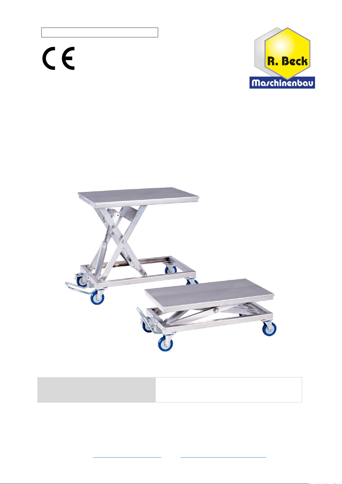
1.2 Illustrations .................................................................................................................................................................................. 4
2Symbols ...................................................................................................................................................................4
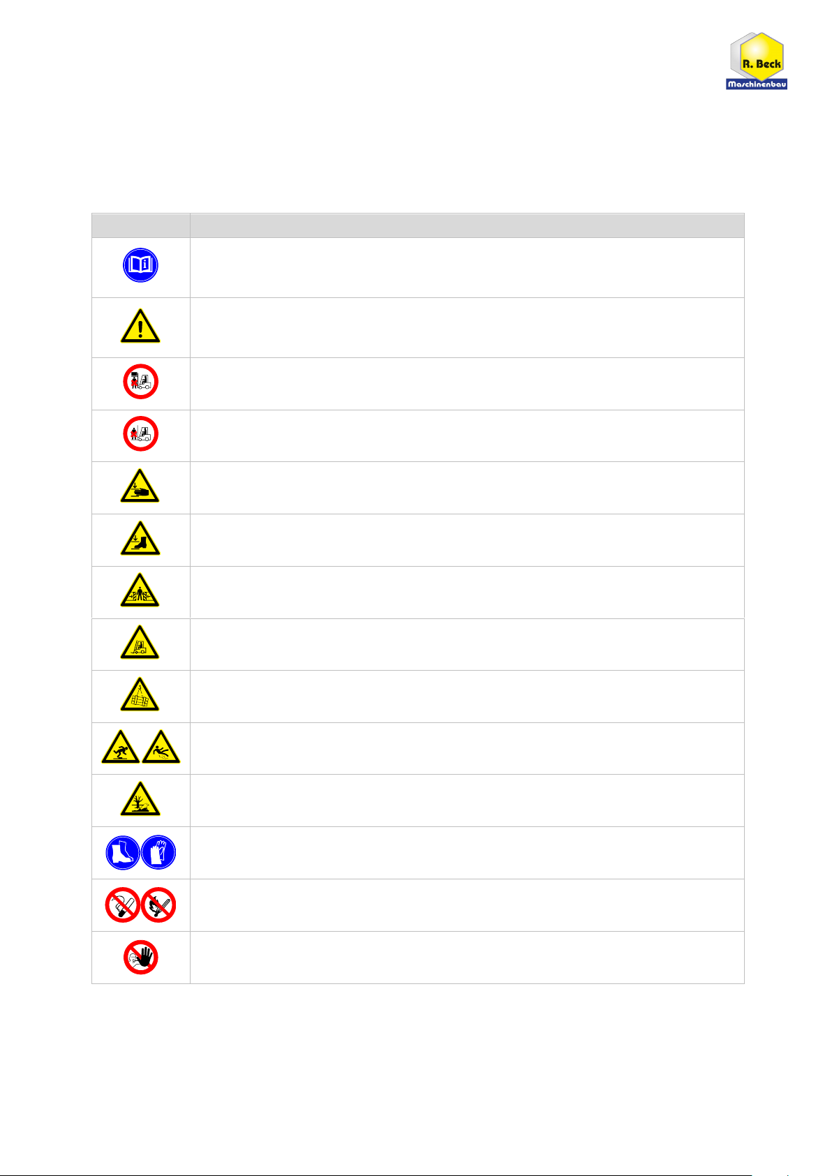
2.1 General Symbols .......................................................................................................................................................................... 4
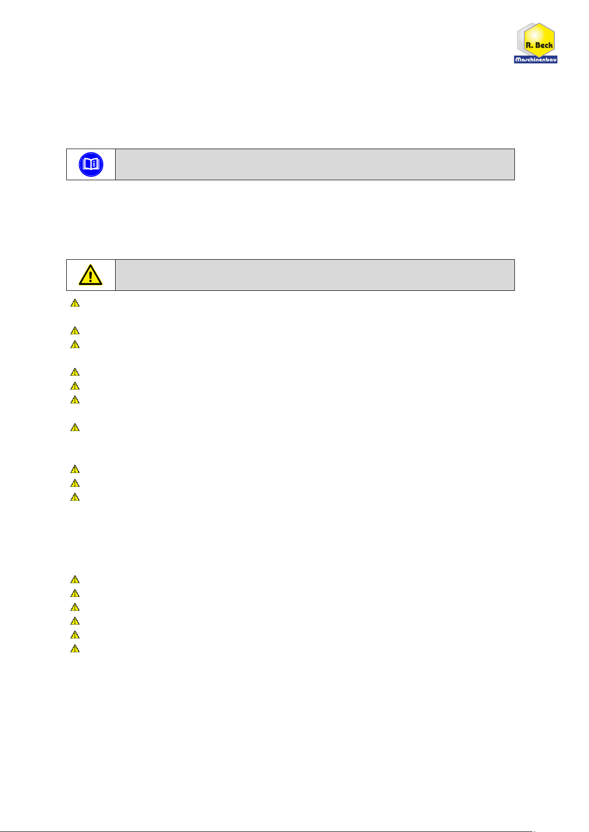
2.2 Symbols in Safety Instructions...................................................................................................................................................... 5
3General ....................................................................................................................................................................6
3.1 Advantages................................................................................................................................................................................... 6
3.2 Applications.................................................................................................................................................................................. 6
3.3 Target Group and Previous Experience ........................................................................................................................................ 6
3.4 Requirements for the Operators.................................................................................................................................................. 6
3.5 Accident Prevention..................................................................................................................................................................... 7
3.6 General Safety Regulations .......................................................................................................................................................... 7
3.7 Standard Equipment .................................................................................................................................................................... 7
3.8 Options and Accessories .............................................................................................................................................................. 7
4Safety.......................................................................................................................................................................8
4.1 Basic Safety Instructions............................................................................................................................................................... 8
4.2 Application Area and Intended Use.............................................................................................................................................. 8
4.3 Improper Use ............................................................................................................................................................................... 8
4.4 Consequences in Case of Disregard.............................................................................................................................................. 9
4.5 Conversions and Modifications of the Lift Tables......................................................................................................................... 9
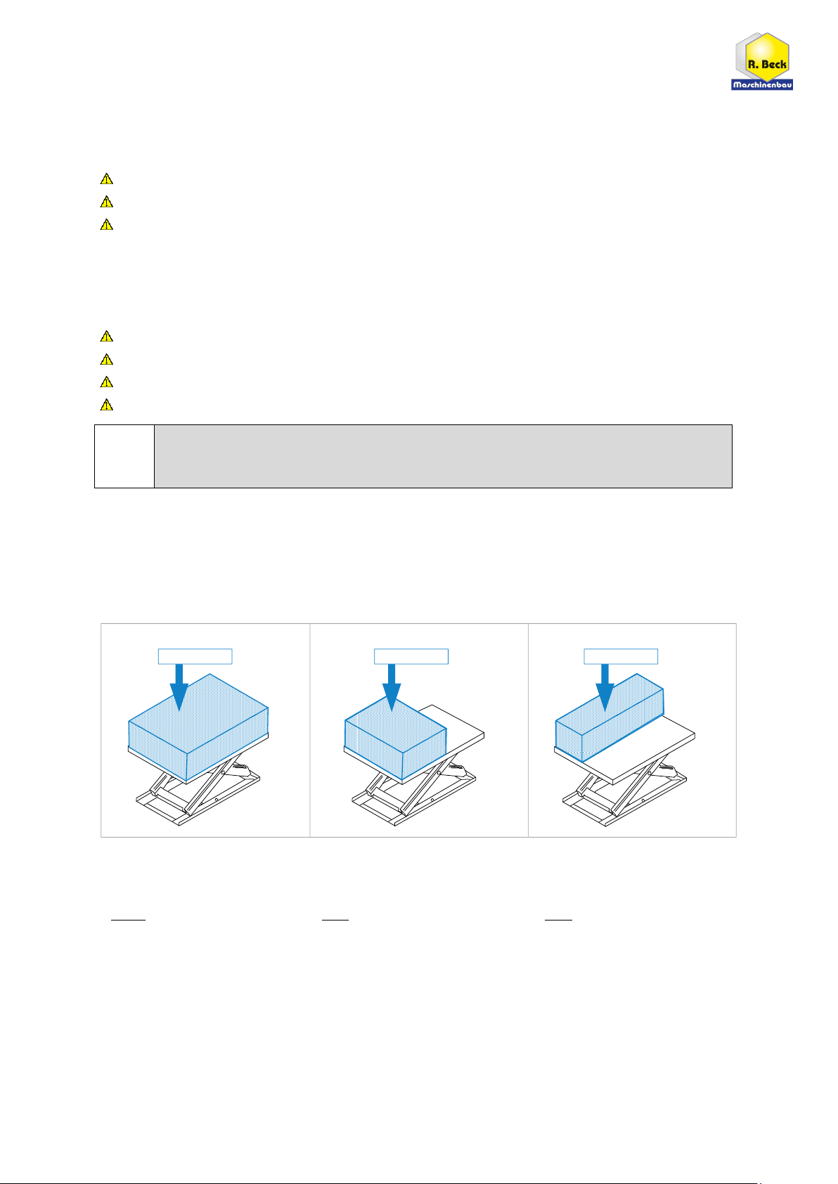
4.6 Load Distribution and Influence on the Nominal Load................................................................................................................. 9
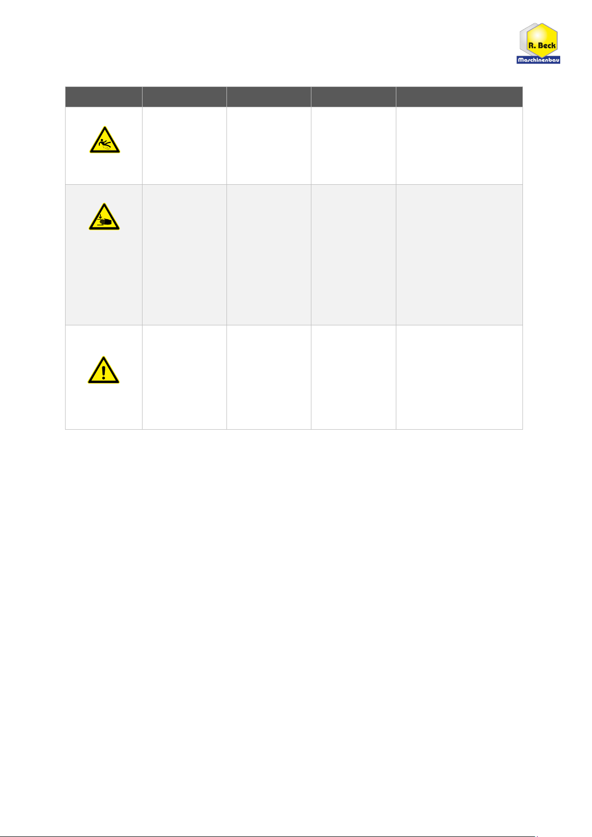
4.7 Hazardous Areas ........................................................................................................................................................................ 10
4.8 Residual Risks............................................................................................................................................................................. 11
4.9 Observe the Environmental Protection Regulations .................................................................................................................. 11
4.10 Organisational Measures ........................................................................................................................................................... 12
4.11 Personnel Selection and Qualification - Basic Duties.................................................................................................................. 12
5Technical Specifications.........................................................................................................................................13
5.1 Manufacturer and Nameplate.................................................................................................................................................... 13
6Transport to the Installation Site...........................................................................................................................14
6.1 Unloading the Lift Table ............................................................................................................................................................. 14
6.2 Requirements for the Installation Site ....................................................................................................................................... 15
6.3 Temporary Storage..................................................................................................................................................................... 15
6.3.1 Short Term Storage ......................................................................................................................................................... 15
6.3.2 Long Term Storage .......................................................................................................................................................... 15
6.4 Lashing on a Transport Vehicle .................................................................................................................................................. 15
7Components and Controls.....................................................................................................................................16
8Installation and Commissioning.............................................................................................................................17
9Operation ..............................................................................................................................................................17
9.1 Load and Unload the Lift Table................................................................................................................................................... 17
9.2 Moving the Lift Table via Swivel Castors .................................................................................................................................... 17
9.3 Lifting and Lowering the Platform.............................................................................................................................................. 17
9.3.1 Height Adjustment .......................................................................................................................................................... 18

3
BA_BM_HS-200_EN_43-21.docx
10 Troubleshooting ....................................................................................................................................................18
11 Maintenance and Repair .......................................................................................................................................19
11.1 Safety Catch for Securing ........................................................................................................................................................... 19
11.1.1 Replacing the Hydraulic Cylinder..................................................................................................................................... 19
11.2 Maintenance Intervals ............................................................................................................................................................... 19
12 Optional Table Tops...............................................................................................................................................20
12.1 Table Top AW 100 Smooth......................................................................................................................................................... 20
12.2 Table Top Beech Multiplex......................................................................................................................................................... 20
12.3 Table Top Hole Grid Multiplex.................................................................................................................................................... 20
13 Decommissioning ..................................................................................................................................................21
14 Disassembly and Scrapping ...................................................................................................................................21
15 Options and Accessories........................................................................................................................................22
15.1 Table Tops.................................................................................................................................................................................. 22
15.1.1 Accessories for Table Top Hole Grid Beech-Multiplex..................................................................................................... 22
EU - Declaration of Conformity.......................................................................................................................................24
List of Figures
Figure 1: Permissible load with load distribution....................................................................................................................... 9
Figure 2: Nameplate................................................................................................................................................................. 13
Figure 3: Components and controls ......................................................................................................................................... 16
Figure 4: Foot bar and brakes................................................................................................................................................... 18
Figure 5: Safety catch for securing ........................................................................................................................................... 19
Figure 6: Table Top AW 100 Smooth........................................................................................................................................ 20
Figure 7: Table Top Beech-Multiplex........................................................................................................................................ 20
Figure 8: Table Top Multiplex Hole Grid................................................................................................................................... 20
Revisions:
Revision
Autor
Modification
Date
001
AG
Original manual translated
25.10.2021

4
BA_BM_HS-200_EN_43-21.docx
1Introduction
The information in this operating manual enables safe, proper and economical operation of your lift table.
Please observe all the explanations, notes and regulations
•to avoid dangers and malfunctions,
•to reduce repair costs and downtimes
•and to increase reliability and service life
of your lift table.
The operating manual must be read and used by each person entrusted with carrying out work with the lift
table. This must be ensured by the operator. Further this manual as well as any appendices and additional
documents must be kept easily accessible at the place of use of the lift table.
Ignorance or non-observance of these operating instructions may result in certain accident
hazards during handling with the lift table. Before commissioning, this operating manual
and any appendices and additional documents must be read thoroughly. All instructions, in
particular the safety regulations, must be observed!
Handling the lift table in the sense of these instructions means
•the installation and commissioning,
•the operation and proper usage,
•the influence on operating conditions, as well as
•the maintenance, troubleshooting and repair.
Apart from the operating manual and the legally binding accident prevention provisions applicable in the coun-
try and place of use, the recognized technical regulations for safe and proper work must also be observed.
1.1 Legal Notice
All contents of these operating instructions are subject to the rights of use and copyright of Reinhold Beck
Maschinenbau GmbH. Any reproduction, modification, further use and publication in other electronic or print-
ed media, as well as their online publication, requires the prior written consent of Reinhold Beck Maschinen-
bau GmbH.
1.2 Illustrations
All photos, figures and graphics contained in this document are for illustration and better understanding only
and may differ from the current state of the product.
2Symbols
2.1 General Symbols
Symbol
Meaning
Indicates passages within this operating manual that must be particularly observed in order to
prevent malfunctions or damage to the lift table.
Refers to chapters, sections, or figures within this document.
Refers to an external document or a third-party source.

5
BA_BM_HS-200_EN_43-21.docx
2.2 Symbols in Safety Instructions
The lift table is designed and manufactured according to the current state of the art. Nevertheless, residual
hazards may occur during handling. In this operating manual, possible dangers and residual risks are pointed
out at appropriate places.
Safety instructions are provided with corresponding danger symbols which have the following meanings:
Symbol
Safety Instruction
Reading and applying the operating manual is mandatory for the operating personnel.
Failure to abide by the following precautions could lead to serious or possibly fatal injury.
General danger symbol, which requires the highest attention!
Failure to observe may result in damage to the equipment, serious injury or even death.
Reference to a prohibited zone under a lifted load!
Do not enter! There is an increased risk of injury or even death.
Reference to a prohibited zone on a platform!
Do not enter! There is an increased risk of injury or even death.
Reference to a possible crushing hazard!
Non-observance increases the risk of injury to hands and fingers!
Reference to a possible crushing hazard!
Non-observance increases the risk of injury to feet and toes!
Possible dangerous crushing hazard in the area of stationary objects!
Risk of personal injury and possibly additional equipment damage.
Reference to a possible hazard due to forklift traffic!
Non-observance can result in life-threatening injuries.
Reference to a possible danger under suspended loads!
Non-observance can result in life-threatening injuries.
Reference to possible tripping and slipping hazards on the floor!
Non-observance may result in minor or severe injuries.
Reference to possible environmental pollution!
Non-observance poses a risk of pollution of the environment and groundwater!
Reference to the obligation to wear safety shoes resp. protective gloves!
Non-observance may result in increased risk of injury to feet & toes or hands & fingers!
Fire hazard! Do not smoke and do not ignite open fire.
Access for unauthorized persons prohibited!
Risk of personal injury and possibly additional equipment damage.

6
BA_BM_HS-200_EN_43-21.docx
3General
The operating manual must be read carefully and understood before handling the
lift table! If anything is unclear, please contact the manufacturer.
The HS 200 lightweight scissor lift table has been specially designed for use outside the company, for example
by service technicians, fitters or craftsmen. Due to its low weight and compact design, it can be quickly and
easily stowed in the service vehicle.
It is therefore suitable for countless applications in industry and trade, e.g. for maintenance, assembly and
repair work in refrigeration industry. The basic model is already equipped with an aluminium table top. Further
table tops are optionally available. These can be plugged onto the substructure and allow individual adaptation
to different applications.
3.1 Advantages
•Mobile lightweight aluminium construction with high load-bearing capacity
•Ideal for service applications thanks to light weight and compact design
•Uniform adjustment to height, even under uneven load distribution
•Back-friendly, foot-operated hydraulic height adjustment
•High-quality, side-mounted hydraulic unit
•Flexible and versatile applications
3.2 Applications
HS 200 can be used for all work corresponding to its intended use in section 4.2. The lift table is suitable for
use as work equipment for transporting, lifting and lowering loads and also as a height-adjustable assembly
table. Typical areas of application are workplaces in manufacturing, assembly and maintenance, where precise
height adjustment for ergonomic working as well as high flexibility and mobility are of particular importance.
The lift table must not be used for work that does not correspond to its intended use (see section 4.2).
3.3 Target Group and Previous Experience
This operating manual is intended for the operating and maintenance personnel of the lift table. The operating
personnel is to be determined by the operator and must further meet the following requirements:
•Basic technical and mechanical knowledge as well as knowledge of the associated technical terms
•Reading and understanding these operating and maintenance instructions
In order to acquire the knowledge required to operate this lift table, the operator must ensure the following
measures:
•Product training for every operator (also possible external personnel)
•Regular safety instruction
3.4 Requirements for the Operators
The operator is responsible for the safe use of the lift table!
The lift table may only be operated by trained personnel who have also read this manual.
Inspection, maintenance, cleaning and repair may only be performed by technical specialists
with product-specific training and mechanical and/or electrical training.
Specialists with product-specific training are to be commissioned and held responsible for
planning and checking the work.
The national protective regulations for employees must be observed
The legal minimum age must be observed.

7
BA_BM_HS-200_EN_43-21.docx
3.5 Accident Prevention
To avoid accidents, the following rules must be observed for operation:
Prevent unauthorized persons from gaining access to the lift table.
Keep unauthorized persons away from the danger areas.
Repeatedly inform present other persons about existing residual risks (see section 4.8 "Residual Risks").
Conduct and record regular training & instruction for persons who must be in the area of the lift table.
New employees must be trained internally to work on a lift table and this training must be documented.
It is not permitted to enter the lift table platform or to transport resp. lift persons.
3.6 General Safety Regulations
In general, the following safety regulations and obligations apply when handling the lift table:
The lift table may only be operated when it is in perfect working order.
It is prohibited to remove, modify or bypass any protective, safety or monitoring equipment.
It is forbidden to modify or alter the lift table without the written approval of the manufacturer / supplier.
Faults or damage must be reported to the operator immediately, eliminated without delay and repaired if
necessary.
Repair and maintenance work on hydraulic components (e.g. hydraulic cylinders) may only be performed
by authorized and trained personnel.
Repair and maintenance work may only be carried out if the lift table has been secured with the safety
catch beforehand (see section 11.1).
Maintenance must be carried out and documented in accordance with the maintenance instructions.
For repairs, only original spare parts from the manufacturer may be used.
Only instructed, trained or qualified persons may work on the lift table.
For the operation of the lift table, the respective national safety regulations for employees as well as the
national safety and accident prevention regulations apply.
3.7 Standard Equipment
•Uniform height adjustment even with uneven load distribution or eccentric loading.
•Stowable in the service vehicle thanks to lightweight aluminium construction and compact design.
•Four swivel castors for mobile use and two parking brakes on the left longitudinal side.
•Stepless foot-operated hydraulic height adjustment up/down via foot bar.
•High load capacity of 200 kg with a tare weight of only 30 kg.
•Safety catch for securing during maintenance work.
•Stable and additionally reinforced scissors.
•Versatile and flexible use.
•CE-compliant design.
3.8 Options and Accessories
Optionally selectable table tops can be found in chapter 12 and further accessories in chapter 15.

8
BA_BM_HS-200_EN_43-21.docx
4Safety
4.1 Basic Safety Instructions
Lift tables can be dangerous if used improperly. Therefore, observe the safety instructions listed in this chapter
and the accident prevention regulations of your employer's liability insurance association!
The manufacturer accepts no liability for damage and malfunctions resulting from failure to
observe these operating instructions.
4.2 Application Area and Intended Use
The foot pedal operated, hydraulically adjustable lift tables of the HS series conform to the Machinery Directive
2006/42/EC and are therefore suitable as technical equipment for both industrial and commercial applications
as well as for training purposes in educational institutions.
Improper use can lead to danger to persons and to a defect or damage to the lift table.
The lift table is primarily intended for operation in covered indoor areas, but it can also be used outdoors
for loading and unloading purposes (e.g. from the service vehicle to the place of use).
Work on the lift table may only be performed at sufficiently illuminated workplaces.
The lift table is intended for processing, equipping, assembling and transporting assemblies, workpieces and
similar components as well as for lifting, lowering and moving loads.
The lift table may only be used on horizontal floors for lifting loads.
The lift table may only be moved when the load is lowered.
The lift table must be positioned freely in the room when lifting and lowering. This means
that no shearing or crushing edges may be caused by the movement of the lift table.
The maximum load (see 5 “Technical Specifications”) with load center in the middle of the lift table must
not be exceeded. If the lift table is loaded unevenly, outside the load center of gravity, the load capacity is
reduced to up to 33 % of the maximum permitted load capacity (see Figure 1).
The lift table is not intended for moving and transporting persons.
The lift table must not be operated in potentially explosive working areas.
Any other use is considered improper and prohibited.
4.3 Improper Use
Improper use is when the lift table is used for purposes other than those prescribed in this operating manual
and in section 4.2, for example
Use and application for private or non-commercial purposes,
Use in disregard of the regulations in the operating manual,
use after unauthorized conversions or modifications,
Exceeding the maximum permissible load (see 5 “Technical Specifications”)
Transporting or conveying persons with the lift table
Entering the lift table
In case of improper use of the lift table, any warranty, liability and other claims for damages of the operator
against the manufacturer are excluded!

9
BA_BM_HS-200_EN_43-21.docx
4.4 Consequences in Case of Disregard
If the lift table is not operated, maintained or repaired in accordance with the safety regulations, not as intend-
ed, improperly or in an abusive manner, the following will result:
Dangers to the health of the operating personnel
Dangers to the lift table and objects in its vicinity
Impairment of the lift table function
In case of improper use of the lift table, any warranty, liability and other claims for damages of the operator
against the manufacturer are excluded!
4.5 Conversions and Modifications of the Lift Tables
Only use the lift table in its original condition, i.e. as delivered!
The components of the lift table must not be changed in their type and condition.
Only original spare parts and accessories from the manufacturer (see 15) may be used.
Deviations are not permitted.
Unauthorized modifications or conversions by the operator, without the written consent of
the manufacturer, are prohibited. This excludes any warranty, liability and other claims for
damages by the operator against the manufacturer!
4.6 Load Distribution and Influence on the Nominal Load
The nominal, maximum permissible load of 200 kg is based on a load evenly distributed on the lift table plat-
form. If the load cannot be distributed evenly on the platform, the maximum permissible load must be reduced
according to the figures below.
Figure 1: Permissible load with load distribution
Even distribution
Load is evenly distributed
over the entire platform area
→100 % of the nominal load
is permissible.
Uneven distribution
Load is distributed over half of the
platform in transverse direction
→50 % of the nominal load
is permissible.
Uneven distribution
Load is distributed over half of the
platform in longitudinal direction
→33 % of the nominal load
is permissible.
max. 100 % max. 50 % max. 33 %

10
BA_BM_HS-200_EN_43-21.docx
4.7 Hazardous Areas
Source
Area
Cause
Risk
Prevention
Foot pump
On the foot bar
for height ad-
justment
Slipping off the
foot bar
Injuries to feet
and legs
Keep foot bar
and shoes dry
Wear work shoes
with non-slip soles
Mechanics
Lifting scissor /
Subframe
Crushing and
shearing points
Loss of limbs,
crushing of hands,
increased risk of
injury and even
death
Do not reach under the
tabletop or into the scissors
during operation and do
not move your body into
this area
Before maintenance work,
always lock the safety catch
to secure the platform first
(see section 11.1)
Hydraulic
system
On hydraulic
cylinders and all
oil-bearing parts,
seals and lines
Oil spraying
out with high
pressure in
case of damaged
cylinder or seals
Injuries and
poisoning of
the eyes
Wear safety goggles
or face shield
Repair damaged parts
and/or seals immediately
(only qualified personnel!)

11
BA_BM_HS-200_EN_43-21.docx
4.8 Residual Risks
The lift table is built according to the latest state of the art and the recognised safety rules. Nevertheless, the
use of the lift table may cause danger to life and limb of the user or third parties or damage to the lift table and
other equipment. Due to the construction of the lift table, the following residual risks can occur even when
used as intended and despite compliance with all relevant safety regulations:
Reading and applying the operating manual is mandatory for the operating personnel.
Be alert to possible crushing hazards:
a) when transporting the lift table by forklift truck: between forks & pallet / lift table
b) when picking up the lift table: between lift table / pallet and floor
c) when lowering the lift table: between lift table and fixed equipment
Be alert to possible crushing hazards when lowering the lift table (from the cargo pallet to the
floor) with a forklift truck or overhead crane.
Be aware of the danger from falling objects such as workpieces, tools or similar. Therefore, wear
safety shoes, especially when transporting and setting down the lift table.
It is strictly forbidden to "ride along" with the lift table during a lifting operation (by means of a
forklift truck or overhead crane). There is a high risk of falling!
It is strictly forbidden to enter or climb onto the lift table during a lifting operation (by means of a
forklift truck or overhead crane). There is a high risk of falling!
Increased risk of injury or even death. Entering the danger zone under a lifted load during transport
or installation by means of a forklift truck is prohibited!
Increased risk of injury or even death. It is forbidden to enter the forklift platform during transport
or installation!
Unauthorised persons are not allowed to enter the lift table installation area (responsibility of the
operator).
Stop! Do not work under the lift table platform until it is mechanically locked via the safety catch.
Non-compliance can result in life-threatening injuries.
Be aware of possible tripping and slipping hazards on the floor. Prevent possible hazards by keep-
ing the floor dry and clean and by using anti-slip floor coverings around the lift table.
Acute danger of crushing underneath the table top! Never reach into the shears and never move
your body into this area! There is an increased risk of accidents with loss of limbs or even death.
When using additional machines on the lift table, first read the respective operating instructions
and comply with the specified safety regulations.
Be aware of the fire hazard during the processing of wood due to wood dust, in connection with
flying sparks and/or open fire!
4.9 Observe the Environmental Protection Regulations
During all work with the lift table, the environmental protection regulations, obligations and laws for waste
avoidance and proper recycling and/or disposal applicable at the place of use must be observed. This applies in
particular to installation, repair and maintenance work involving substances that could pollute the groundwa-
ter (e.g. hydraulic oils and cleaning agents and liquids containing solvents). In any case, prevent them from
seeping into the ground or entering the sewage system.
Store and transport the above-mentioned hazardous substances only in suitable contain-
ers. Avoid leakage of hazardous substances by using suitable collection containers. Ensure
that the above-mentioned substances are disposed of by a qualified disposal company.

12
BA_BM_HS-200_EN_43-21.docx
4.10 Organisational Measures
Always keep this operating manual within easy reach and at the place of use of the lift table.
In addition to the operating manual, observe and instruct on generally applicable legal and other binding
regulations for accident prevention and environmental protection.
Supplement the operating manual with further instructions, including supervisory and reporting duties, to
take account of special operational features (e.g. with regard to work organisation, work processes, per-
sonnel employed).
Before starting work on the lift table, the person responsible for its operation must have read the operat-
ing instructions, especially the chapter "Safety Instructions". This applies in particular to personnel who
only occasionally work on the lift table.
Check that work is carried out in a safety-conscious and hazard-conscious manner and in compliance with
the operating manual.
When using additional machines on the lift table, read the respective operating instructions and keep
them handy. Pay particular attention to the respective safety and hazard information.
In case of safety-relevant changes to the lift table or its operating behaviour, shut down the entire system
immediately and report the fault to the responsible office/person.
Use personal protective equipment as necessary or required by regulations.
Do not make any modifications, additional attachments or conversions to the lift table without the manu-
facturer's approval! This will compromise safety and invalidate the manufacturer's warranty and any lia-
bility claim.
Spare parts must meet the technical requirements specified by the manufacturer. The exclusive use of
original spare parts ensures this. Therefore, only use original spare parts from the manufacturer.
Observe the fire alarm and firefighting possibilities. Make the location and operation of fire extinguishers
(fire class ABC) known. Do not use water!
4.11 Personnel Selection and Qualification - Basic Duties
The design and operation of the lift table is equally suitable for right- and left-handers.
The lift table is designed to be operated by a single person. Other persons in the vicinity of the lift table
must keep a suitable safety distance.
Work on and with the lift table may only be carried out by reliable personnel.
Observe the legal minimum age!
Only use trained or instructed personnel. Clearly define the responsibilities of the personnel for operating,
setting up, maintaining and repairing!
Ensure that only authorised personnel work on the lift table.!
If personnel to be trained or apprenticed have to work on the lift table, this may only be done under the
constant supervision of an experienced resp. qualified person.
Work on hydraulic equipment may only be carried out by authorised and trained personnel.

13
BA_BM_HS-200_EN_43-21.docx
5Technical Specifications
Lift Table Type
HS 200 FH
Article number
180.100.00
Special feature
aluminium lightweight construction
Standard table top material
3 mm thick aluminium sheet
Working platform dimensions1
1000 x 600 x 3 mm
Total height2
1010 mm
Effective stroke
610 mm
Construction height lift table
400 mm
Height adjustment
hydraulically
Control element for height
foot bar
Movable castors
4 pieces (Ø = 125 mm)
Parking brakes
2 pieces (longitudinally mounted)
Load capacity / lifting capacity
max. 200 kg
Net weight2
approx. 35 kg
Hydraulic power units
1 x lateral
5.1 Manufacturer and Nameplate
Manufacturer:
Reinhold Beck Maschinenbau GmbH
Im Grund 23
DE-72505 Krauchenwies (Germany)
Phone: +49 (0) 7576 / 962 978 - 0
Fax: +49 (0) 7576 / 962 978 - 90
Email: [email protected]
Nameplate:
The nameplate provides information about the characteristic values of
your lift table:
Figure 2: Nameplate
Note: Before using the unit in a way that deviates from the described suitability (see section 4.2), it is essen-
tial to consult the manufacturer. Otherwise all warranty, liability and other claims for damages of the operator
against the manufacturer will be voided!
1
For basic model (optionally available table tops are larger, see chapter 12).
2
Specification refers to the basic model without optional table top.

14
BA_BM_HS-200_EN_43-21.docx
6Transport to the Installation Site
Only trained personnel may be used for the following work:
•Transport the lift table
•Unloading the lift table
•Check delivery condition of the lift table
6.1 Unloading the Lift Table
There is an increased risk of accidents when unloading and transporting the lift table!
The lift table can fall or tip over due to its weight!
Use only suitable and technically perfect lifting gear and suspension systems with an
adequate lifting capacity of 500 kg. Only transport the lift table on level, solid ground!
When placing the lift table, pay attention to the possible danger of crushing in the area
of stationary objects around the lift table!
Warning: Increased risk of injury and death! Never stand under the load when lifting
and putting it down! Instruct bystanders to leave the danger zone!
Warning: Increased risk of injury and death! Do not enter or climb onto the forklift
platform during transport!
Increased risk of crushing feet and toes! Wear steel-toed safety shoes!
Unloading by forklift truck
•With the forks set appropriately, drive centrally into the designated places on the freight pallet on the longi-
tudinal side of the lift table and lift carefully.
•Carefully lift the HS 200 from the truck. The weight of the lift table is approx. 35 kg (without accessories).
Check delivery condition
Check for completeness and transport damage. In case of transport damage or missing parts, document these
immediately on the consignment note of the transport company. At the same time, inform the manufacturer of
the situation.
Unpacking and placing
Unpack the lift table and remove the packing material. Lift the HS 200 from the transport pallet with a forklift.
When doing so, drive under the centre of the long side of the lift table with appropriately adjusted forks and
carefully lift slightly. Then lift carefully from the pallet, remove the pallet and set the lift table down on the
ground.
Fire hazard! Do not smoke or light an open fire.
Dispose of the packaging material in an environmentally friendly manner!
Transport to the installation site
After unpacking, the lift table can be moved to the installation site either via its four swivel castors or using a
suitable means of transport. If a forklift or lift truck is used for this purpose, the general safety regulations must
be followed and observed.

15
BA_BM_HS-200_EN_43-21.docx
6.2 Requirements for the Installation Site
The following guidelines apply with regard to space requirements, load-bearing capacity and the condition of
the substrate:
•Space requirements: W x H x D = 1200 x 400 x 700 mm (with standard table top)
W x H x D = 1350 x 430 x 820 mm (with optional table top, see 12)
•Load capacity: Concrete of classification B 15
•Conditions: Level, smooth, non-slip and tilt-free
6.3 Temporary Storage
If the lift table is not put into operation immediately after delivery, it must be stored carefully in a protected
place. Carefully cover the entire lift table so that neither dust nor moisture can penetrate.
6.3.1 Short Term Storage
•Dry environment
•Protect components at risk of corrosion
•Park in a stable place
6.3.2 Long Term Storage
•Dry environment
•Protect components at risk of corrosion
•Protect lift table from dirt
•Park in a stable place
6.4 Lashing on a Transport Vehicle
The lift table must be lashed to the loading area of the transport vehicle on a transport pallet for possible onward
transport. For this purpose, at least two lashing straps with the appropriate load-bearing capacity must be used.
The responsibility for safe loading is borne by the respective shipper!
Please note the following when lashing in the transport vehicle:
•The loading area of the transport vehicle must always be clean and dry.
•The lashing straps used must be suitable for the total weight of the lift table (see chapter 5).
•Fastening on the loading area is done by lashing down: This means that the transport pallet is secured by
frictional locking. The load is pressed so firmly onto the loading surface that it can no longer slip. The clamp-
ing tool should have a high STF value at the frictional connection, e.g. long-lever ratchets.
•In addition, anti-slip mats should be used to provide even more safety.
•The ideal lashing angle (α) for tie-down lashing is 83° to and 90°. Therefore, the lashing straps should pull
downwards approx. vertically. As the angle decreases, the pretensioning force of the lashing is reduced.
•Observe the permissible total weight of the transport vehicle.
•Ensure that the permissible axle loads of the transport vehicle are observed. The load must be distributed
evenly on all axles of the vehicle.
A separate lashing strap must be used for each lashing and must be tensioned individually on the
floor of the loading area of the vehicle! The pallet must also be secured against slipping.

16
BA_BM_HS-200_EN_43-21.docx
7Components and Controls
Figure 3: Components and controls
Pos.
Description
Pos.
Description
1
Foot bar for height adjustment
5
Lift table platform
2
Swivel castor (4 pieces)
6
Hydraulic cylinder
3
Parking brake (2 pieces)
7
Safety catch for maintenance
4
Lifting scissor
Available options and other accessories see chapter 15.
1
2
4
5
3
6
7

17
BA_BM_HS-200_EN_43-21.docx
8Installation and Commissioning
The lift table must be set up in a stable position so that there are no crushing or shearing points between the
lift table and/or the load and objects in the vicinity. Therefore, ensure sufficient space around the lift table. It
must be possible to carry out the intended work on the lift table or the load without obstruction.
The following installation and operating requirements must be observed:
The lift table must be integrated into the existing machinery in such a way that the basic safety require-
ments of the EU Machinery Directive 2006/42/EC are met. This must be checked and ensured by the opera-
tor of the lift table.
The environment must not be explosive.
This operating manual and any supplementary documents must be read carefully and understood.
All safety instructions and regulations must be observed and complied.
9Operation
Before operating the lift table, the operator must ensure that no hazards are caused by the
movement of the lift table platform.
Generally wear steel-toed safety shoes and suitable protective work clothing!
9.1 Load and Unload the Lift Table
When loading or unloading the work platform, the load distribution according to section 4.6 “Load Dis-
tribution and Influence on the Nominal Load“ must be observed and complied with.
A load placed on the lift table must be secured with suitable measures against slipping, tipping over, rolling
away and falling down. This is particularly necessary for loads that have an unstable position on the plat-
form or that do not rest snugly on the lift table plate due to their shape and/or nature (e.g. rolling objects).
9.2 Moving the Lift Table via Swivel Castors
Before moving the lift table, release the two brakes (3) on the long side (see Figure 4 on next page). After-
wards, it can be moved to the desired location. Before starting to work, lock the two brakes (3) again.
Before moving the lift table, the load must always be lowered completely.
Furthermore, the load must be secured by suitable measures against slipping, tipping
over, rolling away and falling down before the lift table is moved.
9.3 Lifting and Lowering the Platform
Before the lift table platform is lifted, the lift table must be fixed in place by the two lockable
brakes on the two front swivel castors.
The procedure for height adjustment follows on the next page.
Tip: If you want to use your lift table for a longer time at the same height position (without adjustment), you
can additionally fix it mechanically with the safety catch (see section 11.1).

18
BA_BM_HS-200_EN_43-21.docx
9.3.1 Height Adjustment
When adjusting the height, make sure that there are no objects between the scissor construction
under the platform and that the safety catch (
11.1) is unlocked.
Be aware of the risk of crushing hands and fingers, especially when positioning downwards. Nev-
er reach into the scissors during height adjustment!
The height adjustment of the lift table is based on the scissor principle. The hydraulic power is transmitted to
the hydraulic cylinder via the foot pump, whereby the foot pump and hydraulic cylinder form a fixed unit. Be-
fore adjusting the height, first secure the lift table against rolling away with the two parking brakes (3).
Figure 4: Foot bar and brakes
•By actuating the foot bar (1) downwards, the hydraulic cylinder
reacts and transfers the force to the scissor unit. The platform
moves upwards gradually with repeated actuation. After approx.
40 actuations the complete lifting height is reached.
•When the foot bar (1) is released, the movement stops and the
working platform remains in this position. In order to adjust the lift
table infinitely and exactly to the desired position, the foot bar (1)
can be released at any point.
•Pulling up the foot bar (1) lowers the work platform for the dura-
tion of the actuation.
10 Troubleshooting
Repair and maintenance work may only be carried out by competent, trained and instructed personnel.
Repair work on mechanical and hydraulic components may only be carried out by
authorised and trained personnel.
Proceed systematically when searching for the cause of a malfunction. If you are unable to find the fault or to
remedy the malfunction, contact our customer service department (phone: 0049 7576 / 962 978 - 0).
Before you call us, please follow these steps:
•Make a note of the information on the nameplate of your lift table (see Figure 2).
•Keep these operating instructions and any supplementary documents at hand.
The more precisely you describe the fault to us, the better we can then remedy the situation.
Possible Faults
Fault
Possible Cause
Remedy
Lift table does not lower
completely to the bottom
Safety catch for maintenance is locked
→Lift the platform little upwards
and unlock the safety catch
Object stuck in lift table scissors
→Remove object
Platform cannot
be lifted up.
Lift table is overloaded
→Reduce load
Hydraulic cylinder, foot pump
or mechanics defective
→Contact customer service
1
2
4
5
3
6
7

19
BA_BM_HS-200_EN_43-21.docx
11 Maintenance and Repair
Maintenance and repair work may only be carried out by competent, trained and instructed personnel. If nec-
essary, further operating instructions and/or additional documents must be observed.
After maintenance or repair work on the lift table, always carry out a function test.
•It is forbidden to reach under the lift table platform before it is secured
with the safety catch (see
section 11.1).
•Wear safety shoes with steel-toed caps.
•Wear suitable protective clothing.
Repair work on mechanical and hydraulic components may only be carried out by authorised
and trained personnel.
Before any maintenance and repair work is carried out, chapter
4 "Safety" must be read
carefully and observed.
11.1 Safety Catch for Securing
Figure 5: Safety catch for securing
The safety catch is primarily used for securing during maintenance work
that has to be carried out underneath the lift table platform. This mainly
includes replacing the hydraulic cylinder.
Since the lift table can no longer be held when the cylinder is removed, it
can fall dangerously. For this reason, the safety catch must generally be
used during maintenance work in the scissor area and underneath the
platform.
To secure the lift table platform, lock the safety catch (7) by folding it down
(see Figure 5).
11.1.1 Replacing the Hydraulic Cylinder
Move the lift table upwards until the safety catch (7) can be folded down. Then fold down the safety catch to
secure the platform (see previous section 11.1). Subsequently lower the lift table until the safety catch is
effective and the hydraulic cylinder is relieved resp. accessible for removal.
Stop! Do not work under the lift table platform until it is mechanically locked via the safety catch.
Non-compliance can result in life-threatening injuries.
11.2 Maintenance Intervals
Interval
Action
Daily
Check all components for damage and have them replaced by competent personnel if neces-
sary. If you have any questions, please contact our support (phone: 0049 7576 / 962 978 - 0).
Monthly
Lubricate the castors and bearings a little.
Annual
Make and document annual inspection of the lift table according to regulations.
7

20
BA_BM_HS-200_EN_43-21.docx
12 Optional Table Tops
The characteristics of the table top depend on the work process and the requirements of the working environ-
ment. Therefore, three different, attachable table tops are optionally available for individual processing forms
and different requirements:
12.1 Table Top AW 100 Smooth
Figure 6: Table Top AW 100 Smooth
•Table top with smooth surface made of all-
weather AW 100 material.
•The table top can be attached to the exist-
ing platform of the HS 200 scissor lift table.
•Platform size: 1250 x 800 x 21 mm
•Weight approx. 14 kg
•Art.-No. 200.100.00
12.2 Table Top Beech Multiplex
Figure 7: Table Top Beech-Multiplex
•Table top made of beech multiplex with
smooth surface.
•The table top is coated with linseed oil and
can be attached to the existing platform of
the HS 200 scissor lift table.
•Platform size: 1250 x 800 x 30 mm
•Weight approx. 24 kg
•Art.-No. 200.101.00
12.3 Table Top Hole Grid Multiplex
Figure 8: Table Top Multiplex Hole Grid
•Table top made of beech-multiplex with
smooth surface, hole grid plate (pitch = 100
mm) and a variety of optional accessories.
•The table top is coated with linseed oil and
can be attached to the existing platform of
the HS 200 scissor lift table.
•Platform size: 1250 x 800 x 30 mm
•Grid holes Ø 22 mm
•Weight approx. 23 kg
•Art.-No. 200.102.00
You will find suitable clamps and supplementary accessories in the sections 15.1 and 15.1.1.
This manual suits for next models
1
Table of contents
Popular Indoor Furnishing manuals by other brands

Sunset Trading
Sunset Trading DLU-BR-TP-3636-T Assembly instructions

Smeg
Smeg SDP20 manual

Ergolux
Ergolux PRO HEIGHT ADJUSTABLE SIT STAND DESK RISER user guide

Whittier Wood
Whittier Wood 1500GACb Assembly instructions

Instant Desks
Instant Desks IDA-1009 Assembly instructions

Kvik
Kvik ST530-060 Assembly instructions

Hausmann
Hausmann 6292 Installation & operation instructions

DITALIA
DITALIA CD-1010 Assembly manual

Cooper Lighting
Cooper Lighting Nuage 301-IP Specification sheet

Room essentials
Room essentials 430238 Assembly instructions

Bedford
Bedford 2 Door Tall/Split Unit Assembly guide

Copeland
Copeland Astrid Assembly instructions