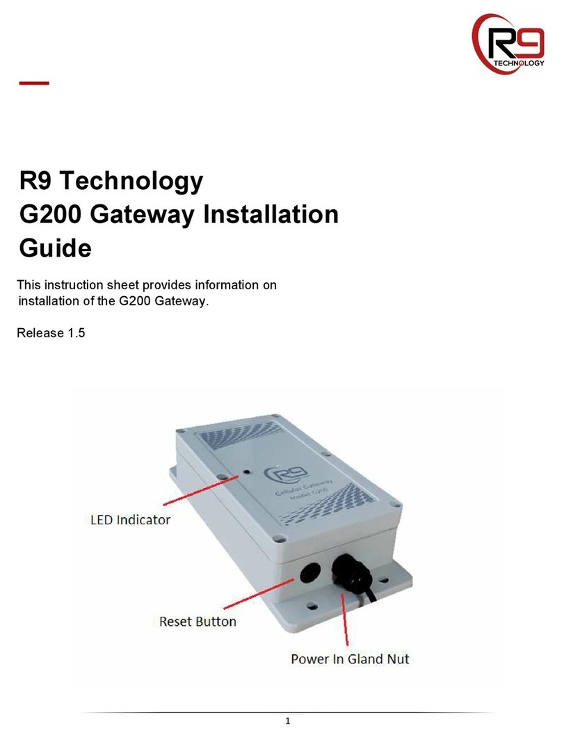
R9 Technology G200 User manual

1
—
R9 Technology
G200 Gateway Overview
This manual provides an overview of R9
Technology’s G200 Gateway.

2
Document Revision
Date Version
Number Document Changes
4/20/2019V0.1InitialRelease

3
TableofContents
1R9 Technology Device Description...................................................................................................................4
1.1 G200 Cellular Gateway Information.........................................................................................................4
1.1.1 Powering the G200 Gateway...............................................................................................................5
1.1.2 Gateway Interfaces..............................................................................................................................5
1.1.3 Gateway Dimensions...........................................................................................................................6
1.1.4 Gateway LED Definition.......................................................................................................................7
2Picogate Installation..........................................................................................................................................8
2.1 Required Items.........................................................................................................................................8
2.2 Mounting Location Considerations...........................................................................................................8
2.3 Installation Instructions.............................................................................................................................9
3FCC Statement...............................................................................................................................................10

(FCC ID:2AQM2SN400), is a bi-directional net
(FCC ID:2AQM2SN400) sensor node. types are available to connect to the SN400(FCC ID:2AQM2SN400) sensor node (Piconode). Various sensor
This section describes R9 Technology’s IOT devices, specifically the G200 Gateway (Picogate), and the SN400
4
1 R9 Technology
Device
Description
The Picogate, G200, is a compact cellular gateway targeted at low cost data collection applications. This device
was designed to take advantage of the latest trends in wireless technology to achieve an easily deployed, low
power sensor network.
The Piconode, SN400 work endpoint capable of supporting both
sensing and control functions. The Piconode is designed to interface with several types of digital sensor devices, as
well as analog sensor devices. This allows for maximum flexibility with sensor selection.
The hardware is deployed in a “star network” configuration as shown in the diagram below.
1.1 G200 Cellular Gateway Information
The G200 cellular gateway provides two local wireless data networks to allow sensor data to flow from sensors, to a web-
based server database. The web server database is where sensor data is stored for later retrieval and analysis by the web
portal.
Wireless data network 1, is based on ISM band 915 MHz wireless technology. This network type is very
low power, while still providing good range and robustness. This wireless network is used by the sensor
node and gateway to transfer sensor data information.
Wireless data network 2, is based on cellular LTE data service. This network has higher performance, and
internet connectivity. The gateway forwards sensor data received from the sensor nodes using an LTE link
to an internet database.
All antennas on the G200 are located internally to the enclosure. This provides protection from damage and provides for a
more robust installation in exposed or mobile applications. In order to use the internal GPS function, direct visibility to the
sky (GPS satellites) is likely required. Usually, location near a window is sufficient for GPS operation.
The G200 includes a Bluetooth Low Energy Interface (2.4GHz). This interface can be used to access the G200’s diagnostic,
status and configuration data.
The G200 can be provisioned with an RS232 port. This will require an optional cable assembly and PCB variant, available
from the factory.

5
1.1.1 Powering the G200 Gateway
The gateway device requires a standard 120V AC outlet for power. Therefore, it will need to be installed near an open AC
outlet. The gateway device should also be installed as high as possible on a wall or beam, and away from large metal
objects when possible. The gateway has four holes on upper and lower flanges for use with fasteners.
The G200 gateway also provides a Lithium Polymer battery-based power backup system. The battery is 3.7V, 2600 mAh,
and will allow the G200 to continue to function if the unit is un-plugged, or AC building power is lost. This battery is not
serviceable by the end user. The G200 battery powered back-up duration is dependent on the update interval used for the
sensor nodes. Battery back-up duration will vary from 24 hours, up to 1 week of operation (for ten-minute sensor update
interval, to one-hour sensor update interval). The internal battery is not designed to provide extended G200 gateway
operation. It allows the gateway to notify the user that a power outage has occurred when AC building power is lost. The
system will then continue to function and report sensor data until the G200 gateway battery is depleted.
1.1.2 Gateway Interfaces
The (standard) IP65 weather resistant enclosure variant of the G200 has only one external connection, this is the DC power
input cable (black gland nut shown below). There are other interfaces available on the G200 PCB, but access requires
removal of the gateway enclosure lid. For specific applications requiring regular access to one of these (optional) interfaces,
a custom cable assembly can be provided.

6
1. Reset Button – Resets the G200 to power on settings.
2. Power Port – 5V-12V DC power can be input using a DC Jack input.
3. Micro-USB – USB port to use as a generic interface. 5V USB power can also be used to power the G200
(alternative to DC power supply input).
4. SIM Card Slot – Location to install the carrier specific SIM card. This is done at the factory.
1.1.3 Gateway Dimensions
The diagram below shows the dimensions of the G200 gateway product. All dimensions are in millimeters.

7
1.1.4 Gateway LED Definition
The gateway product provides one external red/green LED indicator to communicate the status of the gateway to a user.
The LED sequences through three modes below with a slight delay (LED out) between stages. After a final long pause, the
three modes repeat. The gateway LED status loop runs continuously.
Gateway LED Stage 1: LTE Connection status
State Color Blink Count Description
0 Red Solid Power up
1 Orange Solid Initializing
2 Green 2 Connection
3 Red 2 Disconnection
4 Orange 2 Portal Error
5 Red/Green Alternating No SIM
Gateway LED Stage 2: Battery and Charger status
State Color Blink Count Description
0 Off - Power up
2 Red Solid No Plug
3 Green 2 Charging
4 Green Solid Full charge
5 Red/Green Alternating No Battery
Gateway LED Stage 3: 900Mhz Network status
State Color Blink
Count Description
0 Off - Closed
1 Orange 2 Open - Allows device to join

8
2 Picogate Installation
2.1 RequiredItems
Items included with the G200:
• Qty 01, G200 Gateway
• Qty 01, 6’ Power supply (corded)
• Note: The data service SIM card is pre-installed at the factory.
Additional items required depending on the mounting option selected for each node.
• Qty 02, Phillips head sheet rock screws, #10x1”
• Option – Velcro tape kit (replacement for sheet rock screw gateway attachment)
• Small Phillips head screw driver
• Velcro Tape/Tie wraps (optional for cable routing)
2.2 Mounting Location Considerations
1. The G200 gateway must be installed in a secure location and as high as possible for best RF transmission/reception. Attempt
to install sensor nodes as close to the gateway, and as high as possible.
2. Preferred mounting location for the G200 shall be centrally located between the SN400 Sensing Nodes to ensure good signal
reception.
3. To ensure the best signal transmission/reception strength, select an installation location that is free of obstacles that reflect
and absorb radio frequency signals (RF), as well as interference that may distort signals. Avoid installation near or in the
path of strong RF fields. (i.e., computers, microwaves, telecom equipment) and on or near metal objects, air conditioners and
heater ducts since they may cause interference and reduce the G200’s RF performance.
4. Select a location that is not susceptible to drastic temperature changes. A controlled temperature (heating and air-
conditioning) environment is preferred. Also ensure the unit is not exposed to extreme heat or cold so that the enclosure will
not be damaged by external factors (i.e., heat from ovens, cooling racks, exhaust, etc.).
5. Solar loading on the plastic enclosure can heat the electronics inside the case. Avoid mounting locations that are in direct
sunlight at the middle of the day. Mount the gateway under building eaves, or other protected areas.
6. Install the G200 gateway in an “out of the way” location that is not subject to high levels of foot-traffic by people or animals.
Also make sure the G200 does not interfere with usual passage areas by people/employees. Ensure the G200 gateway is
installed in a place that allows easy access for servicing.

9
2.3 Installation Instructions
Once the mounting location has been identified follow the installation steps below:
Step 1
Before physically installing the node, gateway and sensors ensure the units have
good reception in the general area of install (using actual gateway to node data
transfers, see User Guide). If reception is poor an additional site survey will need to
be completed prior to installation.
Step 2
Determine which mounting method to use. Ensure the gateway is oriented so that
the cables are exiting from the bottom of the unit
Screws
oUsing the base plate of the G200 as a template, mark the two holes
for mounting the base plate to the wall. Refer to Figure 1. Ensure the
unit is level.
oDrill or press punch the holes for the two self-tapping screws.
Velcro Tape
oPlace the Velcro tape on the back surface of the G200 gateway
along with its mating counterpart. Do not cover any of the enclosure
screws or regulatory label.
oHold the G200 up to the mounting location and ensure it is level.
oPress the G200 into the wall until proper adhesion between the
Velcro and wall is achieved.
Step 3
Mount the G200 Gateway to the wall using the self-tapping screws or Velcro. If
using Velcro, press gateway to wall and verify good adhesion by the Velcro tape.
Step 4
Plug the power supply into an AC wall outlet (verify the power supply is 120V for US
and/or 220V for Europe). Make sure the AC outlet is functional and has power.
Note: Industrial buildings/locations frequently have un-powered outlets. A hand-held
AC power check device can be used to verify an outlet is powered.
Step 5
Utilize proper cable management techniques to ensure a neat and clean install.
Cable ties and cable tie holders should be used. Refer to Figure 2.
Step 6
Installation is now complete. Verify the G200 Gateway is recognized by the
customer dashboard and can communicate to each SN400 Sensor Node (see User
Guide for details).
Step 7
Proceed to the user guide for additional configuration instructions.
Figure1
Figure2

10
3 FCC Statement
Compliance Statement (Part 15.19)
This device complies with Part 15 of the FCC Rules. Operation is subject to the following two conditions:
1. This device may not cause harmful interference, and
2. This device must accept any interference received, including interference that may cause undesired operation.
Warning (Part 15.21)
Changes or modifications not expressly approved by the party responsible for compliance could void the user’s authority to operate the equipment.
FCC Interference Statement (Part 15.105 (b))
NOTE:
This equipment has been tested and found to comply with the limits for a Class B digital device, pursuant to part 15 of the FCC Rules. These limits are
designed to provide reasonable protection against harmful interference in a residential installation. This equipment generates, uses and can radiate radio
frequency energy and, if not installed and used in accordance with the instructions, may cause harmful interference to radio communications. However,
there is no guarantee that interference will not occur in a particular installation. If this equipment does cause harmful interference to radio or television
reception, which can be determined by turning the equipment off and on, the user is encouraged to try to correct the interference by one or more of the
following measures:
—Reorient or relocate the receiving antenna.
—Increase the separation between the equipment and receiver.
—Connect the equipment into an outlet on a circuit different
from that to which the receiver is connected.
—Consult the dealer or an experienced radio/TV technician for help.
FCC Radiation Exposure Statement:
This equipment complies with the FCC radiation exposure limits set forth for an uncontrolled environment. This equipment should be installed and
operated with a minimum distance of 20cm between the radiator and all persons. This transmitter must not be co-located or operating in conjunction
with any other antenna or transmitter.
—
For questions and support, please contact
R9 Technology
17217 Waterview Parkway Suite 1.202Y
Dallas, TX, 75252, USA
Product information
www.r9tech.com
Support e-mail address
Other manuals for G200
2
Table of contents
Other R9 Technology Gateway manuals
Popular Gateway manuals by other brands

AudioCodes
AudioCodes MediaPack 5 Series Hardware installation manual

Enterasys
Enterasys ANG-1100 Series user guide

EuroTech Communication
EuroTech Communication Winner user manual

LG
LG BNU-LW installation manual

RTA
RTA 460ETCMC-N2E Product user guide

Moxa Technologies
Moxa Technologies MGate MB3000 Modbus user manual