Synway SBO500 SBO Series User manual

Synway SBO Series Gateway
SBO500 Gateway
Version 1.6.3
Synway Information Engineering Co., Ltd
www.synway.net

Synway Information Engineering Co., Ltd
Content
Content ..................................................................................................i
Copyright Declaration...........................................................................iii
Revision History....................................................................................iv
Chapter 1 Product Introduction........................................................1
1.1 Typical Application......................................................................................... 1
1.2 Feature List.................................................................................................... 2
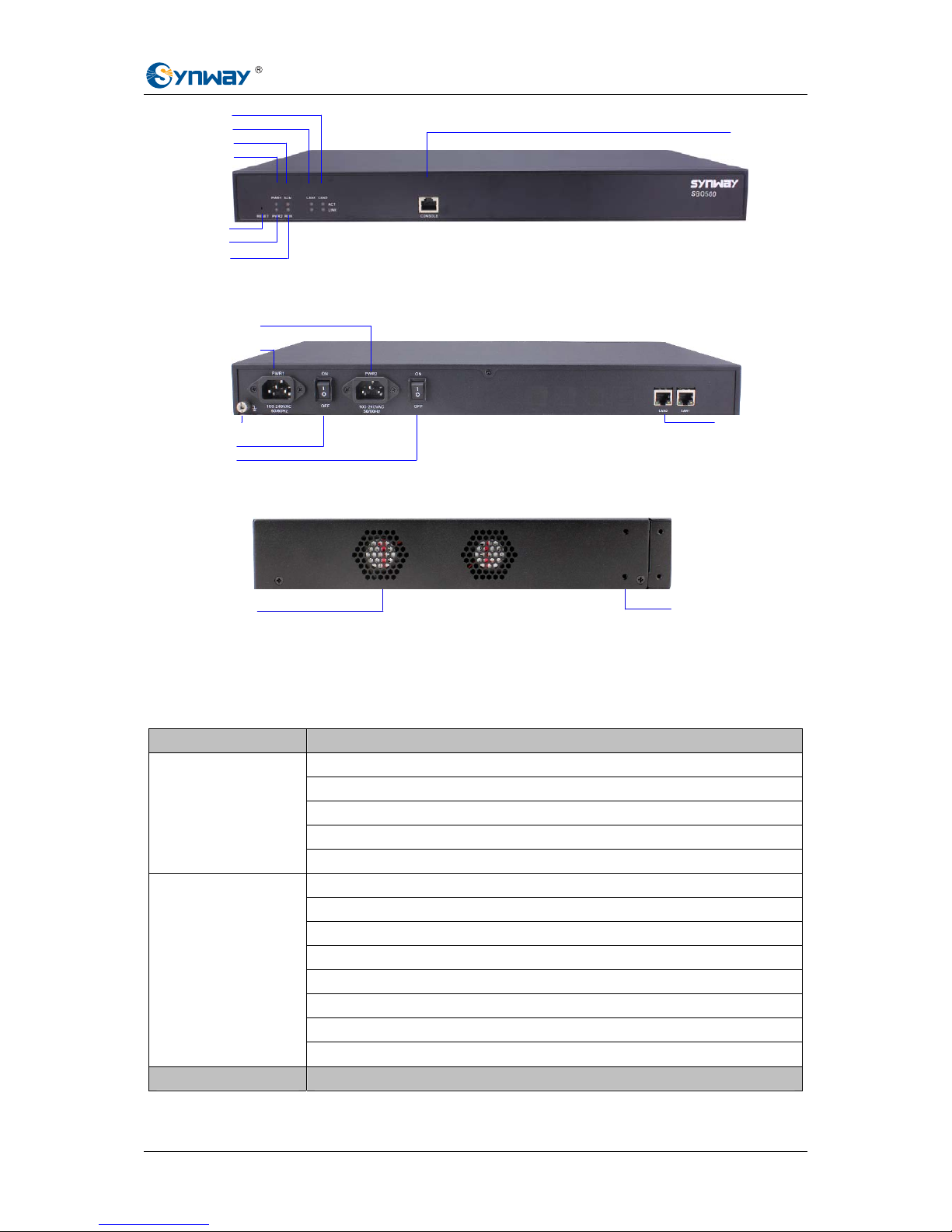
1.3 Hardware Description .................................................................................... 2
1.4 Alarm Info ...................................................................................................... 4
Chapter 2 Quick Guide ......................................................................5
Chapter 3 WEB Configuration...........................................................7
3.1 System Login................................................................................................. 7
3.2 Operation Info................................................................................................ 8
3.2.1 System Info...............................................................................................................8
3.2.2 IP Status .................................................................................................................10
3.2.3 Call Count ...............................................................................................................13
3.2.4 Warning Information ...............................................................................................14
3.3 SIP Settings................................................................................................. 14
3.3.1 SIP Settings ............................................................................................................15
3.3.2 SIP Trunk ................................................................................................................18
3.3.3 SIP Register............................................................................................................21
3.3.4 SIP Account ............................................................................................................24
3.3.5 SIP Trunk Group .....................................................................................................26
3.3.6 Media Settings ........................................................................................................29
3.4 Route Settings............................................................................................. 31
3.4.1 Routing Parameters................................................................................................31
3.4.2 IP to IP ....................................................................................................................32
3.5 Number Filter............................................................................................... 34
3.5.1 Whitelist ..................................................................................................................35
3.5.2 Blacklist ..................................................................................................................37
3.5.3 Number Pool...........................................................................................................38
3.5.4 Filtering Rule...........................................................................................................39
3.6 Number Manipulation................................................................................... 42
3.6.1 IP to IP CallerID ......................................................................................................42
3.6.2 IP to IP CalleeID .....................................................................................................44
3.7 System Tools ............................................................................................... 45
3.7.1 Network ..................................................................................................................46
3.7.2 Management...........................................................................................................47
3.7.3 IP Routing Table......................................................................................................48
3.7.4 Centralized Manage................................................................................................50
3.7.5 Configuration File....................................................................................................52
3.7.6 Signaling Capture ...................................................................................................53
SMG SBO Series Gateway User Manual (Version 1.6.3) Page i

Synway Information Engineering Co., Ltd
3.7.7 Signaling Call Test ..................................................................................................54
3.7.8 Signaling Call Track ................................................................................................55
3.7.9 PING Test ...............................................................................................................56
3.7.10 TRACERT Test .......................................................................................................57
3.7.11 Modification Record ................................................................................................58
3.7.12 Backup & Upload ....................................................................................................59
3.7.13 Factory Reset .........................................................................................................59
3.7.14 Upgrade ..................................................................................................................59
3.7.15 Change Password ..................................................................................................60
3.7.16 Device Lock ............................................................................................................60
3.7.17 Restart ....................................................................................................................61
Chapter 4 Typical Applications.......................................................62
Appendix A Technical Specifications.................................................65
Appendix B Troubleshooting..............................................................66
Appendix C Technical/sales Support.................................................67
SMG SBO Series Gateway User Manual (Version 1.6.3) Page ii

Synway Information Engineering Co., Ltd
Copyright Declaration
All rights reserved; no part of this document may be reproduced or transmitted in any form or by
any means, electronic or mechanical, without prior written permission from Synway Information
Engineering Co., Ltd (hereinafter referred to as ‘Synway’).
Synway reserves all rights to modify this document without prior notice. Please contact Synway
for the latest version of this document before placing an order.
Synway has made every effort to ensure the accuracy of this document but does not guarantee
the absence of errors. Moreover, Synway assumes no responsibility in obtaining permission and
authorization of any third party patent, copyright or product involved in relation to the use of this
document.
SMG SBO Series Gateway User Manual (Version 1.6.3) Page iii

Synway Information Engineering Co., Ltd
Revision History
Version Date Comments
Version 1.0.0 2015-05 Initial publication.
Version 1.6.2 2015-09 New revision
Version 1.6.3 2016-01 New revision
Note: Please visit our website http://www.synway.net to obtain the latest version of this document.
SMG SBO Series Gateway User Manual (Version 1.6.3) Page iv

Synway Information Engineering Co., Ltd
Chapter 1Product Introduction
Thank you for choosing Synway SBO Series Gateway!
The Synway SBO series gateway products (hereinafter referred to as ‘SBO gateway’) are mainly
used for connecting IP or enterprise PBX with the IP telephony network or IP PBX. It provides
such functions as transcoding, routing, number filtration, number manipulation and so on.
Currently, only SBO500 is available for you.
1.1 Typical Application
Figure 1-1 Typical Application
IP Phone IP Phone
Router
LAN
Internet
IP PBX
IMS Server
SBO
Gateway
SMG SBO Series Gateway User Manual (Version 1.6.3) Page 1

Synway Information Engineering Co., Ltd
1.2 Feature List
Basic Features Description
IP Call Call initiated from IP to a designated SIP trunk, via routing and number
manipulation.
Number Manipulation Peels off some digits of a phone number from left/right, or adds a prefix/suffix to a
phone number.
VoIP Routing Routing path: from IP to IP.
Signaling & Protocol Description
SIP Signaling Supported protocol: SIP V1.0/2.0, RFC3261
Voice CODEC G.711A, G.711U, G.729, G723, G722, AMR, iLBC
DTMF Mode RFC2833, SIP INFO, INBAND, RFC2833+Signaling,
In-band+Signaling
Network Description
Network Protocol Supported protocol: TCP/UDP, HTTP, ARP/RARP, DNS, NTP, TFTP, TELNET,
STUN
Static IP IP address modification support
DNS Domain Name Service support
Security Description
Admin Authentication Support admin authentication to guarantee the resource and data security
Maintain & Upgrade Description
WEB Configuration Support of configurations through the WEB user interface
Language Chinese, English
Software Upgrade Support of user interface, gateway service, kernel and firmware upgrades based
on WEB
Tracking Test Support of Ping and Tracert tests based on WEB
SysLog Type Three options available: ERROR, WARNING, INFO
1.3 Hardware Description
The SBO gateway features 1U rackmount design and integrates embedded LINUX system within
the POWERPC+DSP hardware architecture. It has 2 Kilomega-Ethernet ports (NET1 and NET2)
on the chassis. See the figures below for SBO500 appearance:
SMG SBO Series Gateway User Manual (Version 1.6.3) Page 2

Synway Information Engineering Co., Ltd
LAN1 Indicator
Alarm Indicator
Power 1 Indicator
LAN2 Indicator
Console Port
Run Indicator
Power 2 Indicator
Reset Button
Figure 1-2 Front View
Figure 1-3 Rear View
Figure 1-4 Left View
The table below gives a detailed introduction to the interfaces, buttons and LEDs illustrated
above:
Interface Description
Amount: 2
Type: RJ-45
Bandwidth: 10/100/1000Mbps
Self-Adaptive Bandwidth Supported
NET
Auto MDI/MDIX Supported
Amount: 1
Type: RS-232
Baud Rate: 115200 bps
Connector: RJ45 (See Figure 1-5 for signal definition)
Data Bits: 8 bits
Stop Bit: 1 bit
Parity Unsupported
Console Port
Flow Control Unsupported
Button Description
Power1 Key
220V AC Power1
220V AC Power2
Power2 Key
Network Port
Grounding Stud
Ventilation
Holes
Screw Holes for
Foot Bracket
SMG SBO Series Gateway User Manual (Version 1.6.3) Page 3

Synway Information Engineering Co., Ltd
Power Key Power on/off the SBO gateway. You can turn on the two power keys at the same
time to have the power supply working in the hot-backup mode.
Reset Button Restore the gateway to factory settings.
LED Description
Power Indicator Indicates the power state. It lights up when the gateway starts up with the power
cord well connected.
Run Indicator Indicates the running status. For more details, refer to 1.4 Alarm Info.
Alarm Indicator Alarms the device malfunction. For more details, refer to 1.4 Alarm Info.
Link Indicator The green LED on the left of NET, indicating the network connection status.
ACT Indicator The orange LED on the right of NET, whose flashing tells data are being
transmitted.
Note: The console port is used for debugging. While connection, the transmitting and receiving
lines of the gateway and the remote device should be cross-linked. That is, connect the
transmitting line of the gateway to the receiving line of the remote device, and vice verse. The
figure below illustrates the signal definition of the console port on the gateway.
8
7
6
5
4
3
2
1
Gateway TX
Gateway RX
GND
Figure 1-5 Console Port Signal Definition
For other hardware parameters, refer to Appendix A Technical Specifications.
1.4 Alarm Info
The SBO gateway is equipped with two indicators denoting the system’s running status: Run
Indicator (green) and Alarm Indicator (red). The table below explains the states and meanings of
the two indicators.
LED State Description
Go out System is not yet started.
Light up System is starting.
Run Indicator
Flash Device is running normally.
Go out Device is working normally.
Light up Upon startup: Device is running normally.
In runtime: Device goes abnormal.
Alarm Indicator
Flash System is abnormal.
Note:
zThe startup process consists of two stages: System Booting and Gateway Service
Startup. The system booting costs about 1 minute and once it succeeds, both the run
indicator and the alarm indicator light up. Then after the gateway service is successfully
started and the device begins to work normally, the run indicator flashes and the alarm
indicator goes out.
zDuring runtime, if the alarm indicator lights up or flashes, it indicates that the device goes
abnormal. If you cannot figure out and solve the problem by yourself, please contact our
technicians for help. Go to Appendix C Technical/sales Support to find the contact way.
SMG SBO Series Gateway User Manual (Version 1.6.3) Page 4

Synway Information Engineering Co., Ltd
Chapter 2Quick Guide
This chapter is intended to help you grasp the basic operations of the SBO gateway in the
shortest time.
Step 1: Confirm that your packing box contains all the following things.
zSBO Series Gateway *1
zAngle Bracket *2, Rubber Foot Pad *4, Screw for Angle Bracket *8
z220V Power Cord *2
zWarranty Card *1
zInstallation Manual *1
Step 2: Properly fix the SBO gateway.
If you do not need to place the gateway on the rack, simply fix the 4 rubber foot pads. Otherwise,
you should first fix the 2 angle brackets onto the chassis and then place the chassis on the rack.
Step 3: Connect the power cord.
Make sure the device is well grounded before you connect the power cord. Check if the power
socket has the ground wire. If it doesn’t, use the grounding stud on the rear panel of the device
(See Figure 1-3) for earthing.
Note: Each SBO gateway has two power interfaces to meet the requirement for power supply hot
backup. As long as you properly connect and turn on these two power keys, either power supply
can guarantee the normal operation of the gateway even if the other fails.
Step 4: Connect the network cable.
Step 5: Log in the gateway.
Enter the original IP address (NET 1: 192.168.1.101 or NET 2: 192.168.0.101) of the SBO
gateway in the browser to go to the WEB interface. The original username and password of the
gateway are both ‘admin’. For detailed instructions about login, refer to 3.1 System Login. We
suggest you change the initial username and password via ‘System Tools ÆChange Password’
on the WEB interface as soon as possible after your first login. For detailed instructions about
changing the password, refer to 3.7.15 Change Password. After changing the password, you are
required to log in again.
Step 6: Modify IP address of the gateway.
You can modify the IP address of the gateway via ‘System Tools ÆNetwork’on the WEB interface
to put it within your company’s NET. Refer to 3.7.1 Network for detailed instructions about IP
modification. After changing the IP address, you shall log in the gateway again using your new IP
address.
Step 7: Check the channel status.
You can check the status of the channels via ‘Operation Info ÆIP Status’. Refer to 3.2.2 IP Status
for detailed introductions.
Step 8: Set routing rules for calls.
Note: For your easy understanding and manipulation, all examples given in this step do not
involve registration.
Step 1: Configure the IP address of the remote SIP terminal which can establish conversations
with the gateway so that the calls from other terminals will be ignored. Refer to ‘SIP
Settings ÆSIP Trunk’ for detailed instructions. Click Add New to add a new SIP trunk,
SMG SBO Series Gateway User Manual (Version 1.6.3) Page 5

Synway Information Engineering Co., Ltd
fill in ‘Remote IP’ and ‘Remote Port’ with the IP address and port of the remote SIP
terminal which will initiate calls to the gateway. You may use the default values for the
other configuration items.
Example: Provided the incoming IP address of the SIP trunk is 192.168.0.111 and the
port is 5060. Add SIP Trunk 0; set Remote IP to 192.168.0.111 and Remote Port to
5060. The outgoing IP address of the SIP trunk is 192.168.0.222 and the port is 5060.
Add SIP Trunk 1; set Remote IP to 192.168.0.222 and Remote Port to 5060.
Step 2: Add the IP address of the SIP trunks configured in Step 1 into the corresponding SIP
trunk group. Refer to SIP Settings ÆSIP Trunk Group’ for detailed instructions. Click
Add New to add the SIP trunk group. Select the SIP trunk configured in Step 1 as ‘SIP
Trunks’. You may use the default values for the other configuration items.
Example: Add SIP Trunk Group 0. Check the checkbox before 0for SIP Trunks and
keep the default values for the other configuration items.Add SIP Trunk Group 1. Check
the checkbox before 1for SIP Trunks and keep the default values for the other
configuration items.
Step 3: Add routing rules. Refer to ‘Route Settings ÆIPÆIP’ for detailed instructions. Select the
SIP trunk group 0 set in Step 2 as ‘Call Initiator’ and the SIP trunk group 1 set in Step 2
as ‘Call Destination’. You may use the default values for the other configuration items.
Example: Select SIP Trunk Group[0] as Call Initiator and SIP Trunk Group[1] as Call
Destination. Keep the default values for the other configuration items.
Step 4: Initiate a call from the SIP trunk 0 configured in Step 1 to the IP address and port of the
SBO gateway. Thus you can establish a call conversation via SIP trunk[1] with the IP
terminal. (Note: The format used for calling an IP address via SIP trunk is as follows:
username@IP address.)
Example: Provided the IP address of the SBO gateway is 192.168.0.101 and the port is
5060. Provided 123 is a number which conforms to the number receiving rule of the
remote device. Initiate a call from SIP trunk 0 to the IP address 192.168.0.101 (in the
to the number 123.
Special Instructions:
zThe chassis of the SBO gateway must be grounded for safety reasons, according to
standard industry requirements. A simple way is earthing with the third pin on the plug or
the grounding studs on the machine. No or improper grounding may cause instability in
operation as well as decrease in lightning resistance.
zAs the device will gradually heat up while being used, please maintain good ventilation to
prevent sudden failure, ensuring that the ventilation holes (see Figure 1-4) are never
jammed.
zDuring runtime, if the alarm indicator lights up or flashes, it indicates that the device goes
abnormal. If you cannot figure out and solve the problem by yourself, please contact our
technicians for help. Otherwise it may lead to a drop in performance or unexpected
errors.
SMG SBO Series Gateway User Manual (Version 1.6.3) Page 6

Synway Information Engineering Co., Ltd
Chapter 3WEB Configuration
3.1 System Login
Type the IP address into the browser and enter the login interface. See Figure 3-1.
Figure 3-1 Login Interface
The gateway only serves one user, whose original username and password are both ‘admin’. You
can change the username and the password via ‘System Tools ÆChange Password’ on the WEB
interface. For detailed instructions, refer to 3.7.15 Change Password.
After login, you can see the main interface as below.
Figure 3-2 Main Interface
SMG SBO Series Gateway User Manual (Version 1.6.3) Page 7

Synway Information Engineering Co., Ltd
3.2 Operation Info
Operation Info includes three parts: System Info, IP Status, Call Count and Warning Info,
showing the current running status of the gateway. See Figure 3-3.
Figure 3-3 Operation Info
3.2.1 System Info
Figure 3-4 System Info Interface
See Figure 3-4 for the system info interface. You can click Refresh to obtain the latest system
information. The table below explains the items shown in Figure 3-4.
SMG SBO Series Gateway User Manual (Version 1.6.3) Page 8

Synway Information Engineering Co., Ltd
Item Description
MAC Address MAC address of NET 1 or NET 2.
IP Address The three parameters from left to right are IP address, subnet mask and default
gateway of NET 1 or NET 2.
DNS Server DNS server address of NET 1 or NET 2.
Receive Packets
,
Transmit Packets
The amount of receive/transmit packets after the gateway’s startup, including three
categories: All, Error and Drop.
Current Speed The current speed of data receiving and transmitting.
Work Mode
The work mode of the network, including six options: 10 Mbps Half Duplex, 10 Mbps
Full Duplex, 100 Mbps Half Duplex, 100 Mbps Full Duplex, 1000 Mbps Full Duplex
and Disconnected.
Runtime Time of the gateway keeping running normally after startup. This parameter
updates every 2s.
Serial Number Unique serial number of a SBO gateway.
WEB Current version of the WEB interface.
Gateway Current version of the gateway service.
Uboot Current version of Uboot.
Kernel Current version of the system kernel on the gateway.
Firmware Current version of the firmware on the gateway.
SMG SBO Series Gateway User Manual (Version 1.6.3) Page 9

Synway Information Engineering Co., Ltd
3.2.2 IP Status
Figure 3-5 IP Status Interface
See Figure 3-5 for the IP status interface which shows the real-time status of each IP channel on
the gateway.
Item Description
Channel No. The corresponding serial number of IP on the device.
State zDisplays the channel state in real time. You can move the mouse onto the
channel state icon for detailed information about the channel and the call, such
SMG SBO Series Gateway User Manual (Version 1.6.3) Page 10

Synway Information Engineering Co., Ltd
as: call direction, calling party number and called party number. The channel
states include:
State Icon Description
Idle The channel is available.
Wait Answer The channel receives the ringback tone and is waiting
for the called party to pick up the phone.
Ringing The channel is in the ringing state.
Talking The channel is in a conversation.
Pending The channel is in the pending state
Dialing The channel is dialing.
Wait Message The channel is waiting for the message from remote
PBX.
Note: The gateway provides the fuzzy search feature on this interface. After you click any
characters on Figure 3-5 and press the ‘F’ button, the search box will emerge on the right top of
this page. Then you can input the key characters and the gateway will locate the channel on
which there is an ongoing call that conforms to the fuzzy search condition.
Take an example: As shown in Figure 3-6, after we input the character 114 to the search box, and
click the Search button, the gateway does a fuzzy search and locates that the ongoing call whose
CalledID contains the character 114 occurs on Channel 10 of Channel Group 1.
SMG SBO Series Gateway User Manual (Version 1.6.3) Page 11

Synway Information Engineering Co., Ltd
Figure 3-6 Search Calls
SMG SBO Series Gateway User Manual (Version 1.6.3) Page 12

Synway Information Engineering Co., Ltd
3.2.3 Call Count
Figure 3-7 Call Count Interface
See Figure 3-7 for the call count Interface. The above list shows the detailed information about all
the calls counted from the startup of the gateway service to the latest open or refresh of this
interface. You can click Reset to count the call information again, click Download to download the
call count logs. The table below explains the items shown in Figure 3-7.
Item Description
Release Reason Reason to release the call.
Normal
Disconnection Total number of the calls which are normally cleared.
Cancelled Total number of the calls which are cancelled by the calling party.
Busy Total number of the calls which fail as the called party has been occupied and
replies a busy message.
No Answer Total number of the calls which fail as the called party does not pick up the call in a
long time or the calling party hangs up the call before the called party picks it up.
Routing Failed Total number of the calls which fail because no routing rules are matched.
No Idle Resource Total number of the calls which fail because no voice channel is available.
Failed Total number of the calls which fail as the called party number does not conform to
the number-receiving rule or for relative reasons.
Others Total number of the calls which fail because of other reasons.
Number Total number of the calls on each state.
Percentage The percentage of the calls with a release cause to total calls.
SMG SBO Series Gateway User Manual (Version 1.6.3) Page 13

Synway Information Engineering Co., Ltd
3.2.4 Warning Information
Figure 3-8 Warning Information Interface
See Figure 3-8 for the Warning Information interface. All the warning information will be output
and displayed on this interface.
3.3 SIP Settings
SIP Settings includes six parts: SIP, SIP Trunk, SIP Register, SIP Account, SIP Trunk Group
and Media. See Figure 3-9. SIP is used to configure the general SIP parameters; SIP Trunk is
used to set the basic and register information of the SIP trunk; SIP Register is used for the
registration of SIP; SIP Account is used for registering SIP accounts to the SIP server; SIP Trunk
Group is to manage SIP trunks by group; and Media is to set the RTP port and the payload type.
Figure 3-9 SIP Settings
SMG SBO Series Gateway User Manual (Version 1.6.3) Page 14

Synway Information Engineering Co., Ltd
3.3.1 SIP Settings
SMG SBO Series Gateway User Manual (Version 1.6.3) Page 15
Table of contents
Other Synway Gateway manuals

Synway
Synway SMG Series User manual

Synway
Synway SMG-D Series User manual

Synway
Synway SBC Series User manual

Synway
Synway Uniway2000 User manual

Synway
Synway SMG1002-2S User manual

Synway
Synway SMG2030L User manual

Synway
Synway SMG1004B User manual

Synway
Synway SBO Series User manual

Synway
Synway SBO Series User manual

Synway
Synway SMG2030 User manual

Synway
Synway SMG Series User manual

Synway
Synway SBO Series User manual

Synway
Synway SMG4004 User manual

Synway
Synway SMG Series User manual

Synway
Synway SMG1008 User manual

Synway
Synway SMG1008 User manual

Synway
Synway SMGREC User manual

Synway
Synway SMG4002 User manual

Synway
Synway SMG-C Series User manual

Synway
Synway SMG Series User manual