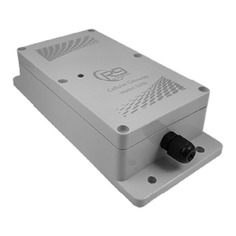
R9 Technology G200 User manual

1
—
R9 Technology
G200 Gateway Installation
Guide
This instruction sheet provides information on
installation of the G200 Gateway.
Release 1.5

2
Refer to the R9 Technology installation video located online:
www.r9technology.com/resources-videos
Required Items:
Items included with the G200:
• Qty 01, G200 Gateway
• Qty 01, DC Power supply (Includes 10-foot power cord)
• Qty 02, Phillips head screws, #10 screw, 1 inch in length
• Note: The LTE data service SIM card is pre-installed at the factory.
Additional items required depending on the mounting option selected for each node.
• Small Phillips head screw driver
• Option- Other fasteners types or double-sided foam adhesive tape can also be used to install the G200 gateway.
Mounting Location Considerations:
1. Mount the G200 above a 120V 60Hz power outlet. The G200 gateway should be installed as high as possible for best RF
(wireless) performance.
2. Attempt to install sensor nodes close to the gateway (but do not install nodes closer than 5 feet). Also install sensor nodes
as high as possible on equipment, for best wireless (RF) performance. The gateway should be in the center of the sensor
node grouping.
3. To ensure the best wireless performance select a “free-space” installation location that is not near, or covered by, large metal
objects. Avoid mounting the gateway to concrete walls or metal surfaces (wood or sheet-rock mounting surface is preferred).
If no wood or sheet-rock surfaces are available, then mounting to metal, concrete, or brick surfaces is acceptable.
4. For indoor operation, select a location that is not exposed to drastic temperature changes, and not in direct sunlight. Avoid
areas of temperature extremes (for example, heat from ovens, cooling racks, hot exhaust).
5. Install the G200 gateway in an “out of the way” location that does not affect the daily movement and working conditions of
persons or employees Ensure the G200 gateway is installed in a place that allows easy access for servicing (removal of lid,
or removal of complete G200 device from the wall).
6. For outdoor operation, solar loading on the plastic enclosure can heat the electronics inside the case. Avoid mounting
locations that are in direct sunlight, especially at mid and late day. Mount the gateway under building eaves, or other
protected areas. A solar hood will be required when mounting in direct sunlight.

3
Figure 2
Installation Instructions:
After a suitable installation location has been identified for the gateway,
follow the installation steps below:
Step 1
Setup Gateway and Sensor Nodes in Portal - use the Safezone
portal dashboard to setup your account, gateway, and sensor node
devices. Steps for online setup of the node/gateway system are
located in the R9 Online Portal User Guide. Log in and select the
configuration menu to input your device information.
Step 2
Test Gateway Operation - Before permanently installing the gateway
device, ensure the gateway and node devices have a good wireless
connection, after placing the devices in the general area of install (If
system communication / reception is not possible, the units will have to
be moved for improved wireless performance. Except in extreme
cases, your system will have plenty of wireless range for optimal
performance.
Test Gateway - Cellular LTE service for the gateway is good as
indicated by two “quick blink” green LED flashes at the start of the LED
indication sequence (first two of four blinks). If first two LED blinks are
green, LTE service is good. The gateway does not have to be
provisioned in the portal for LTE service indication. The gateway only
has to be powered on by plugging in to wall power.
Test Sensor Node(s) - Gateway and sensor node devices must be
provisioned in the online portal for node connectivity to be tested.
Wireless connection from the gateway to each node device is good if
the node devices will pair to the gateway. Quick press the pair button
on the node (marked P). If the LED flashes green, the node is paired to
the gateway and the wireless connection is good. If the LED flashes
red, the node device has not paired yet. After the entry of the device
serial numbers into the portal, the pairing should happen within 3 to10
minutes.
There is no power switch on the gateway device. When the G200
gateway is plugged into AC power for the first time, the unit will power
on and initialize (boot up). After ~ 30 seconds of initialization, the
gateway will output a faint audible chime, and the front LED will start to
flash. The unit will then remain powered by the internal battery, even if
the AC plug is disconnected from the wall socket. Note that pressing
the reset button while the gateway is un-plugged will cause the unit to
power down.
AC power outlets located inside closets, or in the back of industrial
buildings may not be active. If gateway power is lost, or the gateway is
moved to an up-powered plug, then the second “long green flash” in the
LED flash sequence will turn into two red “quick LED flashes”. See the
Gateway Hardware User Guide for more information on the LED
status indication. Two LED red flashes indicates that AC power outlet
is off or not powered (third and fourth blinks).
Step 3
Mount the Gateway – Mount the gateway (up high) using the two
provided screws. Mount using one screw at top, and one at bottom.
Screws should be at a diagonal to each other. Place small holes in the
wall to allow the screws to start. Ensure the gateway is oriented so that
the cables are exiting from the bottom of the unit. Note that it is ok to
place the gateway on a shelf, desk, or other location without
permanent mounting. Alternatively, some customers use double
sided foam tape to mount the gateway, as it is very light.
Step 4
Power Gateway Device - Plug the gateway power supply into an AC
wall outlet (120V, 60 Hz. for USA). Bundle any excess power cable
and make sure it is out of the way.

4
Installation is now complete! Verify the G200 Gateway is recognized
in the online portal, and can communicate to each SN400 sensor node.
Steps for provisioning of the node/gateway system, and general
operation of the web-based dashboard are located in the R9 Online
Portal User Guide.
Installation Considerations:
1. Do not over-use tape, screws, or other fasteners, as removal and servicing of the system may be necessary in the future.
2. Heat from ovens, or hot exhaust can adversely affect GATEWAY operation. Avoid these areas for installation.
3. Only install the gateway in weather protected areas, out of direct sunlight. If installed outdoors, select areas that are protected
from direct weather such as under the eaves of a building.

5
—
For questions and support, please contact
R9 Technology
17217 Waterview Parkway Suite 1.202Y
Dallas, TX, 75252, USA
Product information
www.r9tech.com
Support e-mail address
Other manuals for G200
2
Table of contents
Other R9 Technology Gateway manuals
Popular Gateway manuals by other brands

Multitech
Multitech MultiConnect Conduit IP67 Base Station Hardware installation guide

ZyXEL Communications
ZyXEL Communications AMG1312-T10D user guide

JVA
JVA PTE0320 quick start guide

ITS Telecom
ITS Telecom CGW-T4 Installation and programming manual

ZyXEL Communications
ZyXEL Communications ZYWALL USG 20W quick start guide

Unex
Unex NexIP IS050s user manual