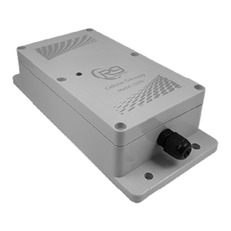
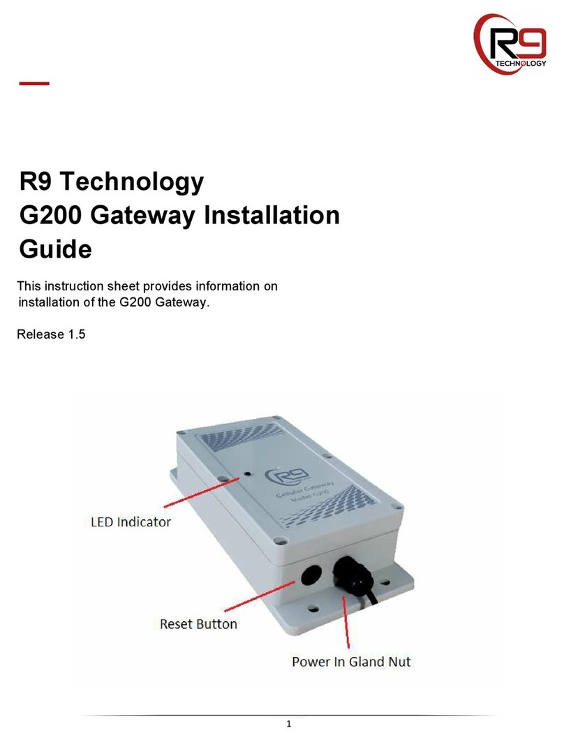
R9 Technology G200 User manual

User Guide
Copyright © 2020 R9 Technology Inc. All rights reserved. i
G200 Gateway Hardware User Guide
October 2020
Release 1.5
R9 Technology
17217 Waterview Parkway Suite 1.202Y
Dallas, TX 75252
www.r9technology.com

User Guide
Copyright © 2020 R9 Technology Inc. All rights reserved. ii
Document Revisions
Date Version
Number Document Changes
06/10/2020 R1.4 First release of the document
10/15/2020 R1.5 Entry of IMEI/SN into portal, change to last 5 digits. Update G200
temp range.

User Guide
Copyright © 2020 R9 Technology Inc. All rights reserved. iii
Table of Contents
1 Introduction ................................................................................................................................................................ 4
2 G200 Product Label ................................................................................................................................................. 5
3 Wireless Operating Bands (Antennas) ............................................................................................................ 7
4 Power ............................................................................................................................................................................. 8
5 Interfaces, Indicators and Buttons .................................................................................................................... 9
6 Installation ................................................................................................................................................................ 12
7 Dimensions ............................................................................................................................................................... 13
8 Sales and Warranty Policy ................................................................................................................................. 13
6 Specifications ........................................................................................................................................................... 14
7 Certifications - United States FCC Statement ............................................................................................. 15

Copyright © 2020 R9 Technology Inc. All rights reserved. 4
1 Introduction
This User Guide covers specific hardware features of R9 Technologies model G200
wireless LTE gateway device. The gateway device is used to gather data from one or
several sensor nodes (using a local wireless sensor network), and will then use an LTE
wireless data link to transfer this sensor data to a database located on an internet-based
server. The database can be used by customers to view and analyze the gathered sensor
information
The G200 device’s position in the overall network can be seen in the diagram below.
The G200 “Picogate” is the second device from the far-right end of the network diagram,
shown below. It gathers sensor information from SN400 sensor devices. This sensor
data will, ultimately, be viewed and analyzed on a user’s personal computer or smart
device using a web-browser. Alerts which are received via SMS text can also be
implemented using the R9 web-based system.
An LTE carrier SIM card is installed into the G200 at the factory. The G200 is powered
on, by plugging it into an AC power outlet (120V, 60 Hz.). The device will initialize, and
then immediately connect to the LTE network, local to your area. To get the G200
device to start collecting and forwarding sensor data, it will have to be “onboarded” into
the R9 online portal system. The R9 Online Portal User Guide lists specific steps
required to onboard your gateway device into the portal system.
The G200 cellular gateway provides two local wireless data networks. These two
networks are used to allow sensor data to travel from the sensor node devices, to a web-

Copyright © 2020 R9 Technology Inc. All rights reserved. 5
based server database. The web server database is where sensor data is stored for later
retrieval and analysis by the web portal.
Wireless data network 1: the sensor network is based on ISM band 915
MHz wireless technology. This network type is very low power, while
still providing good range and robustness. This wireless network is used
by the sensor node and gateway to transfer sensor data information.
Wireless data network 2: the LTE cellular network allows the gateway to
access and store information on web servers. This network has higher
complexity and power requirements, but also higher performance. The
gateway forwards sensor data received from the sensor nodes using an
LTE link to an internet database.
2 G200 Product Label
The G200 product label located on the rear face of the device will indicate several important
parameters. This product label is shown in the picture below.
1. The IMEI ID, circled in red, in the picture below, is unique to each G200 device. The
last 5 digits of the IMEI ID will be entered into the online portal system during setup,
and is used to identify the G200. Note that the IMEI ID is actually derived from the
identifier number of the carrier SIM card. The G200 serial number is also indicated
on the label.
2. The complete model number of the G200 device indicates the specific configuration
of a particular device variant. Includes optional features installed, such as antenna
configuration, DC power supply type, internal battery type, enclosure type,
enclosure color, etc.

Copyright © 2020 R9 Technology Inc. All rights reserved. 6
The standard G200 model number is G200-HACAAAC. This part number indicates:
H – Optional features: no optional features are provisioned (GPS, Accelerometer,
BLE radio, digital expansion port).
A(1) – Antenna configuration: all system antennas are internal and PCB
mounted.
C(1) – Auxiliary serial port configuration: configured for bi-directional mode.
A(2) - Battery: internal LiPo backup battery is installed.
A(3) – External USB cable: external USB cable is not installed.
A(4) – Power Supply: external DC power supply installed, 12V, 2A, 120V,
60Hz.
C(2) – Enclosure type: Water resistant IP65 rated plastic case, gray color.

Copyright © 2020 R9 Technology Inc. All rights reserved. 7
This specific part number is the default G200 variant manufactured by R9 Technology, and
is suitable for most applications. Consult the factory for more information on available
G200 model number variants.
3 Wireless Operating Bands (Antennas)
Sensor Network: The G200 will use only the 915 Mhz ISM band (United States) to
wirelessly connect to, and transmit/receive data from the sensor node devices. The
frequency range of operation is 902 Mhz to 928 Mhz The G200 uses a frequency
hopping algorithm to minimize generated noise and improve immunity from external RF
interference. An 868 Mhz ISM band (European) version of the G200 is also available
(G201).
The G200 915 Mhz antenna is PCB mounted and located internally to the enclosure.
Note that it is possible to connect an external antenna to the G200 device. This is
supported only as an option, and should not be necessary in a typical application.
LTE Data Network: The LTE data network is used by the G200 to wirelessly transmit
sensor data from the node devices to internet-based web servers. The G200 uses an LTE
category 1 radio for this purpose. The LTE bands of operation are bands 2,4, and 12.
Band 2 - 1900 Mhz, Band 4 - Extended AWS 1700/2100 Mhz, Band 12 - 700 Mhz
BLE Radio: The BLE radio is optional, and is not used in a typical system. The BLE
radio could be used as a secondary sensor network, or for wireless configuration of the
G200 device. The BLE band of operation is 2.4 GHz.
GPS Receiver: The GPS receiver is optional, and is not used in a typical system. The
GPS receiver (receive only) operates between the frequencies of 1559 Mhz to 1609 Mhz.
These frequencies are in the standard operating band for GPS/GNSS.

Copyright © 2020 R9 Technology Inc. All rights reserved. 8
4 Power
The gateway does not have an external power switch. The G200 device is powered
on by plugging the DC power supply into a 120V, 60 Hz., AC wall outlet. This supply
type is used in the United States (220V 50 Hz. will be used in other parts of the world).
POWER ON: When the G200 gateway is plugged into an AC outlet for the first time,
the unit will power on, initialize, and finally emit a short, audible chime to indicate it is
operating. Also, the front LED will turn RED for a few seconds when the unit is first
plugged in. Once the G200 has successfully initialized (20-30 seconds), it will output a
short, audible beep, and the LED will start to flash. Note that after initialization, the
G200 will remain powered by the battery, even if the AC plug is disconnected from the
wall socket.
The G200 gateway provides a single Lithium Polymer (LiPo) battery for use as a
power backup system. The battery is 3.7V, 2600 mAh (milli-Ampere hour), and will
allow the G200 to continue to function if the unit is un-plugged, or AC building power is
lost. This battery is not accessible by the customer. The G200 battery powered back-up
time duration is dependent on several factors. The two main items that affect battery run-
time are the data update rate (minutes or hours) used for the sensor nodes, and the
quantity of nodes in the system. Battery back-up run-time is approximately 10 to 20
hours of operation. The internal battery is not designed to provide extended G200
gateway operation. It allows the gateway to notify the user that a power outage has
occurred when AC building power is lost. The system will then continue to function and
report sensor data until the G200 gateway battery is depleted. Note: Although the
battery capacity is physically 2600 mAh, the battery capacity is de-rated as implemented
(less capacity), so that the battery is not stressed and will have a longer operational life.
POWER OFF: The G200 gateway is powered off much like a smart phone. Because it
(internally) uses a “OS based file system”, the G200 is not instantly powered off, it
should be “shut down” to allow proper closing of the internal file system. Note that
because it is battery powered, “pulling the plug” on the G200 will not turn the unit off.
To power off the G200 device:
1 – Remove the DC power supply from the wall socket. The G200 will continue to
function normally from battery power.
2 - “Quick press” the reset button located on the bottom left of the G200. The G200
will make a brief audible chirp, and the LED will start to flash GREEN quickly.

Copyright © 2020 R9 Technology Inc. All rights reserved. 9
3 – After a few seconds, the LED will change to solid RED. The G200 has actually
closed all devices and restarted (re-booted). While the LED is still RED, “quick
press” the reset button again. The G200 will now power itself off, and the LED
indicator will turn off. The unit is now powered down, and is in “ship mode”.
IMPORTANT: When you first power up the G200 gateway (from an off state), the reset
button is in-operable. The reset button will not start to function until after the G200 has
successfully initialized. This is indicated by a longer audible beep after 20-30 seconds.
HARD RESET: If there are un-recoverable issues with the G200, first attempt to power-
cycle the unit (as indicated above) by pushing the reset button quickly. This reboots the
gateway and provides a SOFT RESET of the system, and completely re-initializes the
device. If this does not clear a problem, or the device is not responsive, then a HARD
RESET will be required. Hold the reset button in for 8 seconds, and then release the reset
button. The LED will turn RED in color, and the system has been reset (without shut-
down). The unit will power up normally. Do not implement a HARD RESET unless
absolutely necessary.
5 Interfaces, Indicators and Buttons

Copyright © 2020 R9 Technology Inc. All rights reserved. 10
The (standard) IP65, water resistant enclosure variant of the G200 has few external
indicators or buttons. This hardens the device against weather exposure and moisture.
The only external connections on the (standard) G200 are:
1. Power supply cable (through gland nut)
2. Reset push-button.
3. Tri-color LED indicator (red, green, orange)
Cabling and most protrusions through the case will exit at the bottom of the case to help
prevent moisture ingress. Operation of the reset button is discussed in the power section,
as it is used to power off the device. LED indicator information is discussed in the
paragraph below. There are other interfaces available on the G200 PCB. Some of these
interface features may be accessible using external cabling (not installed for typical
monitoring application). Remaining PCB interfaces are also listed below.
1. Micro-USB – USB high speed port. USB cable power (5V) can also be used to
power the G200 (alternative to standard DC power supply input).
2. SIM Card Slot – SIM card installation is done at the factory.
3. Option: DC Barrel Jack Port – 5V-12V DC power can be input using a DC power
supply.
4. Option: Digital expansion port.
5. Option: Serial expansion port.
6. Option: external antenna port (LTE, 915 Mhz ISM, GPS).
LED Indicator: The gateway product provides one external red/green/orange LED
indicator to communicate the status of the gateway to a user. The LED sequences
through two stages, with a slight time delay (LED out) between stages. The two-stage
gateway LED indication sequence loops continuously. Note that during G200 gateway
initialization, the LED will at first display red until the G200 processor sets the LED

Copyright © 2020 R9 Technology Inc. All rights reserved. 11
color. Then the LED will display solid green for a few seconds. Once the G200 is
initialized properly, the LED flash status will loop continuously as indicated in the table
below.
Gateway LED Stage 1: LTE Connection status (starts after long LED out
pause)
State Color Blink
Count
Description
1 Green 2 LTE connection good
2 Red 2 LTE not connected
3 Orange 2 LTE portal error- the R9 data portal
connection has low through-put or is not
connected.
4 Red/Green
Alternating
LTE SIM card not installed
Gateway LED Stage 2 (after short LED out pause): Battery and Charger
status
State Color Blink
Count
Description
1 Red 2 AC Plug not inserted in wall outlet, or AC
power is off
2 Green 2 LiPo battery Charging
3 Green Solid LiPo battery full charge
4 Red/Green
Alternating
LiPo battery not installed (not detected)

Copyright © 2020 R9 Technology Inc. All rights reserved. 12
6 Installation
The gateway device should be installed as high as possible on a wall or beam, and away
from large metal objects (for best wireless performance). The gateway should,
preferably, be installed on a wood or sheet-rock surface. Concrete, brick, or metal walls
and surfaces should be avoided.
If the gateway is installed out-doors, make sure it is not installed in direct sunlight.
Install the gateway in a dry, shaded area such as under the eaves of a building. I shade is
not available, then the G200 gateway should be installed under a solar shade covering
accessory.
The gateway has four holes on upper and lower flanges for mounting to a surface with
screw fasteners. In some installations, it may be preferable to use double sided adhesive
foam tape.
The G200 should always be installed with the power supply cable exiting the enclosure
downwards (for the first few inches of cable at the least). This prevents moisture from
traveling along the cable and into the enclosure. Antennas on the (standard) G200 are
located internally to the enclosure. This provides protection from damage and provides
for a more robust installation in exposed or mobile applications.
A separate document, the G200 Installation Guide is available that covers the
installation of the G200 product at a user site.

Copyright © 2020 R9 Technology Inc. All rights reserved. 13
7 Dimensions
The dimensions of the G200 gateway are shown below. All Dimensions are shown in
millimeters (mm).
8 Sales and Warranty Policy
Please download the Sales Warranty Policy document from our website at
www.r9technology.com. It is located on the “Resources/Documentation” web page.

Copyright © 2020 R9 Technology Inc. All rights reserved. 14
6 Specifications
Data service: LTE-Cat 1 (5Mbps Up / 10Mbps Down)
Integrated LTE cellular antenna
Integrated 915/868 MHz ISM band antenna and sensor network
Software-defined radio (SDR) ISM band wireless chipset
915 MHz sensor node to gateway data rate 5 Kbps at up to 2km (affected by device
orientation, antennas, and local conditions)
AES128 encryption providing secure sensor node communication
128Mbit FLASH storage memory for local data logging applications
Data service SIM card port (4FF)
External green/red/orange tri-color LED indicator for unit operation status
Piezo-based speaker provides audible alarm/alert indication
Includes internal battery backup, rechargeable Li-ion polymer battery (2600 mAH);
Continues operation in power outage conditions
Supports sleep mode for low power operation, ideal for remote applications
Power input: 12V DC power supply (included)
0 C to 40 C (32 F to 105 F) temperature operating range (limited by on-board
lithium polymer battery)
Overall dimensions: 157 mm length x 91 mm width x 47 mm thickness
IP65 rated ABS plastic enclosure
Optional 2.4 GHz sensor node interface allows for maximum flexibility in sensor
selection and operation
Optional GNSS/GPS solution for location services; Internal PCB mounted antenna is
standard, external GPS antenna option (using MMCX connector)
Optional external LTE cellular antenna (using MMCX connector)
Optional 915 MHz external antenna (using MMCX connector)
Optional USB 2.0 high-speed port cable for data transfer and/or 5V power input
Optional RS232 / serial port cable

Copyright © 2020 R9 Technology Inc. All rights reserved. 15
7 Certifications - United States FCC Statement
Compliance Statement (Part 15.19)
This device complies with Part 15 of the FCC Rules. Operation is subject to the following two
conditions:
1. This device may not cause harmful interference, and
2. This device must accept any interference received, including interference that may cause
undesired operation.
Warning (Part 15.21)
Changes or modifications not expressly approved by the party responsible for compliance
could void the user’s authority to operate the equipment.
FCC Interference Statement (Part 15.105 (b))
NOTE:
This equipment has been tested and found to comply with the limits for a Class B digital
device, pursuant to part 15 of the FCC Rules. These limits are designed to provide
reasonable protection against harmful interference in a residential installation. This
equipment generates, uses and can radiate radio frequency energy and, if not installed and
used in accordance with the instructions, may cause harmful interference to radio
communications. However, there is no guarantee that interference will not occur in a
particular installation. If this equipment does cause harmful interference to radio or
television reception, which can be determined by turning the equipment off and on, the user
is encouraged to try to correct the interference by one or more of the following measures:
—Reorient or relocate the receiving antenna.
—Increase the separation between the equipment and receiver.
—Connect the equipment into an outlet on a circuit different
from that to which the receiver is connected.
—Consult the dealer or an experienced radio/TV technician for help.
FCC Radiation Exposure Statement:
This equipment complies with the FCC radiation exposure limits set forth for an
uncontrolled environment. This equipment should be installed and operated with a
minimum distance of 20cm between the radiator and all persons. This transmitter must not
be co-located or operating in conjunction with any other antenna or transmitter.
Other manuals for G200
2
Table of contents
Other R9 Technology Gateway manuals