Racal Instruments MULTIPLEXER PLUG-IN 1260-134 User manual

1260 VXI
SWITCHING CARD
1260-134
MULTIPLEXER PLUG-IN
PUBLICATION NO. 980824-134
RACAL INSTRUMENTS
United States
(Corporate Headquarters and Service Center)
4 Goodyear Street, Irvine, CA 92618
Tel: (800) 722-2528, (949) 859-8999; Fax: (949) 859-7139
5730 Northwest Parkway Suite 700, San Antonio, TX 78249
Tel: (210) 699-6799; Fax: (210) 699-8857
Europe
(European Headquarters and Service Center)
18 Avenue Dutartre, 78150 LeChesnay, France
Tel: +33 (0)1 39 23 22 22; Fax: +33 (0)1 39 23 22 25
29-31 Cobham Road, Wimborne, Dorset BH21 7PF, United Kingdom
Tel: +44 (0) 1202 872800; Fax: +44 (0) 1202 870810
Via Milazzo 25, 20092 Cinisello B, Milan, Italy
Tel: +39 (0)2 6123 901; Fax: +39 (0)2 6129 3606
Technologie Park, Friedrich Ebert Strasse, 51429 Bergisch Gladbach, Germany
Tel: +49 (0) 2204 844200; Fax: +49 (0) 2204 844219
info@racalinstruments.com
sales@racalinstruments.com
helpdesk@racalinstruments.com
http://www.racalinstruments.com/
PUBLICATION DATE: August 05, 2003
Copyright 1998 by Racal Instruments, Inc. Printed in the United States of America. All rights reserved.
This book or parts thereof may not be reproduced in any form without written permission of the publisher.

THANK YOU FOR PURCHASING THIS RACAL INSTRUMENTS PRODUCT.
For this product, or any other Racal Instruments product that incorporates software drivers, you
may access our web site to verify and/or download the latest driver versions. The web address for
driver downloads is:
http://www.racalinstruments.com/downloads
You will be asked to register one time only to gain access to the driver and product manual
downloads sections. At registration a cookie will be placed on your computer if you choose to
accept it. This is done to facilitate your use of these sections on future visits. You may refuse to accept the
cookie and still have complete access to the software driver database but will have to re-register every time
you visit. This cookie is for ease of use only and no information is gathered for, sold, or reported to, any third
party organization.
If you have any questions about software driver downloads or our privacy policy, please contact us at
info@racalinstruments.com.
WARRANTY STATEMENT
All Racal Instruments, Inc. products are designed and manufactured to exacting standards and in full
conformance to Racal’s ISO 9001 procedures.
This warranty does not apply to defects resulting from any modification(s) of any product or part without
Racal’s express written consent, or misuse of any product or part. The warranty also does not apply to fuses,
software, non-rechargeable batteries, damage from battery leakage, or problems arising from normal wear,
such as mechanical relay life, or failure to follow instructions.
This warranty is in lieu of all other warranties, expressed or implied, including any implied warranty of
merchantability or fitness for a particular use. The remedies provided herein are buyer’s sole and exclusive
remedies.
For the specific terms of your standard warranty, or optional extended warranty or service agreement, contact
your Racal customer service advisor. Please have the following information available to facilitate service.
1. Product serial number
2. Product model number
3. Your company and contact information
You may contact your customer service advisor by:
E-Mail: Helpdesk@racalinstruments.com
Telephone: +1 800 722 3262 (USA)
+44(0) 8706 080134 (UK)
+852 2405 5500 (Hong Kong)
Fax: +1 949 859 7309 (USA)
+44(0) 1628 662017 (UK)
+852 2416 4335 (Hong Kong)

RETURN of PRODUCT
Authorization is required from Racal Instruments before you send us your product for service or calibration.
Call your nearest Racal Instruments support facility. A list is located on the last page of this manual. If you are
unsure where to call, contact Racal Instruments, Inc. Customer Support Department in Irvine, California, USA
at 1-800-722-3262 or 1-949-859-8999 or via fax at 1-949-859-7139. We can be reached at:
helpdesk@racalinstruments.com.
PROPRIETARY NOTICE
This document and the technical data herein disclosed, are proprietary to Racal Instruments, and shall not,
without express written permission of Racal Instruments, be used, in whole or in part to solicit quotations from
a competitive source or used for manufacture by anyone other than Racal Instruments. The information herein
has been developed at private expense, and may only be used for operation and maintenance reference
purposes or for purposes of engineering evaluation and incorporation into technical specifications and other
documents which specify procurement of products from Racal Instruments.
DISCLAIMER
Buyer acknowledges and agrees that it is responsible for the operation of the goods purchased
and should ensure that they are used properly and in accordance with this handbook and any
other instructions provided by Seller. RII products are not specifically designed, manufactured or
intended to be used as parts, assemblies or components in planning, construction, maintenance or
operation of a nuclear facility, or in life support or safety critical applications in which the failure of
the RII product could create a situation where personal injury or death could occur. Should Buyer
purchase RII product for such unintended application, Buyer shall indemnify and hold RII, its
officers, employees, subsidiaries, affiliates and distributors harmless against all claims arising out
of a claim for personal injury or death associated with such unintended use.

FOR YOUR SAFETY
Before undertaking any troubleshooting, maintenance or exploratory procedure, read carefully the
WARNINGS and CAUTION notices.
This equipment contains voltage hazardous to
human life and safety, and is capable of
inflicting personal injury.
If this instrument is to be powered from the AC line (mains) through an
autotransformer, ensure the common connector is connected to the neutral (earth
pole) of the power supply.
Before operating the unit, ensure the conductor (green wire) is connected to the
ground (earth) conductor of the power outlet. Do not use a two-conductor extension
cord or a three-prong/two-prong adapter. This will defeat the protective feature of the
third conductor in the power cord.
Maintenance and calibration procedures sometimes call for operation of the unit with
power applied and protective covers removed. Read the procedures and heed
warnings to avoid “live” circuit points.
Before operating this instrument:
1. Ensure the proper fuse is in place for the power source to operate.
2. Ensure all other devices connected to or in proximity to this instrument are properly grounded or
connected to the protective third-wire earth ground.
If the instrument:
- fails to operate satisfactorily
- shows visible damage
- has been stored under unfavorable conditions
- has sustained stress
Do not operate until, performance is checked by qualified personnel.


This page was left intentionally blank.

1260-134 User Manual
i
Table of Contents
Chapter 1...........................................................................................................................1-1
SPECIFICATIONS .......................................................................................................................1-1
Introduction ..............................................................................................................................1-1
Specifications ...........................................................................................................................1-2
About MTBF .............................................................................................................................1-3
Ordering Information ................................................................................................................1-4
Chapter 2...........................................................................................................................2-1
INSTALLATION INSTRUCTIONS................................................................................................2-1
Unpacking and Inspection ........................................................................................................2-1
Reshipment Instructions...........................................................................................................2-1
Installation ................................................................................................................................2-1
Module Configuration ...............................................................................................................2-2
Front Panel Connectors ........................................................................................................2-2
Mating Connectors................................................................................................................2-7
Chapter 3...........................................................................................................................3-1
MODULE OPERATION................................................................................................................3-1
Setting the Module Address .....................................................................................................3-1
Operating Modes......................................................................................................................3-2
Operating In Message-Based Mode .........................................................................................3-4
Channel Descriptors For The 1260-134 ................................................................................3-4
Reply To The MOD:LIST? Command ...................................................................................3-5
Operating The 1260-134 in Register-Based Mode ...................................................................3-5
1260-134 Example Code ......................................................................................................3-9
Chapter 4...........................................................................................................................4-1
OPTIONAL ASSEMBLIES .......................................................................................................... 4-1

1260-134 User Manual
ii
Chapter 5...........................................................................................................................5-1
PRODUCT SUPPORT.................................................................................................................5-1
Product Support .......................................................................................................................5-1
Reshipment Instructions...........................................................................................................5-1
Support Offices ........................................................................................................................5-2

1260-134 User Manual
iii
List of Figures
Figure 1-1, The 1260-134 ............................................................................................................1-1
Figure 2-1, Block Diagram of 1260-134 .......................................................................................2-3
Figure 2-2, Front-Panel Connector Pin Numbering ......................................................................2-4
Table 2-1, 1260-134 Front-Panel Connections ............................................................................2-5
Figure 3-3, Message-Based Mode of Operation ..........................................................................3-3
Figure 3-4, Register-Based Mode of Operation............................................................................3-3
List of Tables
Table 2-1, 1260-134 Front-Panel Connections ........................................................................... 2-5

1260-134 User Manual
iv
This page was left intentionally blank.

1260-134 User Manual
Racal Instruments Ó2003 Specification 1-1
Chapter 1
SPECIFICATIONS
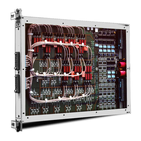
Introduction The 1260-134 is a 16 (1X4) 2 wire multiplexer plug-in switch
module developed for the Racal Instruments 1260-100 Adapt-a-
Switch Carrier. The 1260-134 includes the following features:
· Standard Adapt-a-Switch plug-in design, providing for ease of
replacement
· Data-Driven embedded descriptor, allowing immediate use with
any Option-01T switch controller, regardless of firmware
revision level.
Figure 1-1, The 1260-134

1260-134 User Manual
Specification 1-2 Racal Instruments Ó2003
Specifications Bandwidth (-3dB) 100 MHz
Insertion Loss
10 MHz < 0.5 dB
50 MHz < 1 dB
Isolation
100 KHz > 50 dB
1 MHz > 40 dB
Crosstalk
100 KHz < -50 dB
1 MHz < -40 dB
Switching Voltage
AC 250 V, Max
DC 220 V, Max
Switching Current
AC 2 A, Max
DC 2 A, Max
Switching Power
AC 125 VA, Max
DC 60 W, Max
Path resistance < 500 mW
Thermal EMF < 10 uV
Capacitance
Channel to Chassis < 100 pF
Open Channel < 5 pF
Insulation resistance > 109W
Relay Settling Time < 10 ms
Shock 30g, 11 ms, ½ sine wave
Vibration 0.013 in. P-P, 5-55 Hz
Bench Handling 4 in., 45°
Cooling See 1260-100 cooling data
Temperature
Operating 0°C to +55°C
Non-operating -40°C to +75°C
Relative Humidity 85% + 5% non-condensing at

1260-134 User Manual
Racal Instruments Ó2003 Specification 1-3
< 30°C
Altitude
Operating 10,000 feet
Non-operating 15,000 feet
Power Requirements
+5 VDC 150mA + 30mA per energized relay
(2A Max.)
Weight 1.0 lb. (0.45 kg.)
MTBF 749095 hours (MIL-HDBK-217E)
Dimensions 4.5”H X 0.75”W X 9.5”D
About MTBF The 1260-134 MTBF is 749095 hours, calculated in accordance
with MIL-HDBK-217E, with the exception of the electromechanical
relays. Relays are excluded from this calculation because relay life
is strongly dependent upon operating conditions. Factors affecting
relay life expectancy are:
1. Switched voltage
2. Switched current
3. Switched power
4. Maximum switching capacity
5. Maximum rated carrying current
6. Load type (resistive, inductive, capacitive)
7. Switching repetition rate
8. Ambient temperature
The most important factor is the maximum switching capacity,
which is an interrelationship of maximum switching power,
maximum switching voltage and maximum switching current.
When a relay operates at a lower percentage of its maximum
switching capacity, its life expectancy is longer. The maximum
switching capacity specification is based on a resistive load, and
must be further de-rated for inductive and capacitive loads.
For more details about the above life expectancy factors, refer to
the data sheet for the switch plug-in module.

1260-134 User Manual
Specification 1-4 Racal Instruments Ó2003
The relay used on the 1260-134 plug-in is Racal part no.
310256-001. The relay manufacturer’s specifications for this relay
are:
Life Expectancy
Mechanical 100,000,000 operations
Electrical 100,000 operations at full rated load
(resistive)
For additional relay specifications, refer to the relay manufacturer’s
data sheet.
Ordering
Information
Listed below are part numbers for both the 1260-134 switch
module and available mating connector accessories. Each
1260-134 uses a single mating connector.
ITEM DESCRIPTION PART #
1260-134 Switch Module Switch Module, 16 (1X4) 2 wire
multiplexer, 2 A Consisting of:
P/N 405133-001 PCB
Assembly
P/N 980824-134 Manual
407662
160-pin Mating Connector 160 Pin Conn. Kit with pins 407664
Cable Assy. 6ft, Sleeved 160 Pin Cable Assy, 6 Ft, 24 AWG 407408-001
Additional Manual 980824-134

1260-134 User Manual
Racal Instruments Ó2003 Installation Instructions 2-1
Chapter 2
INSTALLATION INSTRUCTIONS
Unpacking and
Inspection
1. Before unpacking the switching module, check the exterior of
the shipping carton for any signs of damage. All irregularities
should be noted on the shipping bill and reported.
2. Remove the instrument from its carton, preserving the factory
packaging as much as possible.
3. Inspect the switching module for any defects or damage.
Immediately notify the carrier if any damage is apparent.
4. Have a qualified person check the instrument for safety before
use.
Reshipment
Instructions
1. Use the original packing material when returning the switching
module to Racal Instruments for servicing. The original
shipping carton and the instrument’s plastic foam will provide
the necessary support for safe reshipment.
2. If the original packing material is unavailable, wrap the
switching module in an ESD Shielding bag and use plastic
spray foam to surround and protect the instrument.
3. Reship in either the original or a new shipping carton.
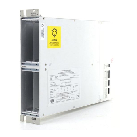
Installation Installation of the 1260-134 Switching Module into a 1260-100
Carrier assembly is described in the Installation section of the
1260-100 Adapt-a-Switch Carrier Manual.

1260-134 User Manual
Installation Instructions 2-2 Racal Instruments Ó2003
Module
Configuration
The 1260-134 contains sixteen 1x4 multiplexers. Each channel of
each multiplexer is independently controlled. Thus, the user can
simultaneously connect any combination of four input channels to
the common port of the multiplexer.
For a block diagram of the 1260-134, refer to Figure 2-1.
Front Panel
Connectors
The 1260-134 has one 160-pin front-panel connector, labeled
J200. It is a 160-pin, modified DIN style, with 0.025” square posts
as pins. It has one pin for each input and one for each output. See
Figure 2-2 for numbering. Table 2-1 shows the mapping of
channel numbers to connector pins. Information about available
mating connectors is provided immediately after Table 2-1.

1260-134 User Manual
Racal Instruments Ó2003 Installation Instructions 2-3
Figure 2-1, Block Diagram of 1260-134
K0
K1
K2
K3
E2
D1
A
1
B1
K4
K5
K6
K7
B2
C3
D3
E4
K8
K9
K10
K11
B4
D5
C7
A7
K12
K13
K14
K15
E19
C13
A
11
C11
K16
K17
K18
K19
E12
D11
B10
E10
K20
K21
K22
K23
D9
B8
E6
B6
K24
K25
K26
K27
E8
B14
E14
D13
K28
K29
K30
K31
B12
D15
E16
B16
K48
K49
K50
K51
D21
B21
B28
E28
K52
K53
K54
K55
E29
D30
B30
E31
K56
K57
K58
K59
D32
B32
D27
B26
K60
K61
K62
K63
C29
A
29
C31
A
31
K44
K45
K46
K47
D23
B22
E22
B20
K32
K33
K34
K35
E18
B18
A
15
C17
K36
K37
K38
K39
A
17
E20
A
23
C23
K40
K41
K42
K43
E26
D25
B24
E24
K0
K1
K2
K3
D2 00
E1 01
A2 02
C1 03
K4
K5
K6
K7
C2 10
B3 11
E3 12
D4 13
K8
K9
K10
K11
C4 20
E5 21
B7 22
A8 23
K12
K13
K14
K15
D19
B13
A12
B11
K16
K17
K18
K19
D12
E11
C10
D10
K20
K21
K22
K23
E9
C8
D6
C6
K24
K25
K26
K27
D8
C14
D14
E13
K28
K29
K30
K31
C12
E15
D16
C16
K48
K49
K50
K51
E21
C21
C28
D28
K52
K53
K54
K55
D29
E30
C30
D31
K56
K57
K58
K59
E32
C32
E27
C26
K60
K61
K62
K63
B29
A30
B31
A32
K44
K45
K46
K47
E23
C22
D22
C20
K32
K33
K34
K35
D18
C18
A16
B17
K36
K37
K38
K39
A18
D20
A24
B23
K40
K41
K42
K43
D26
E25
C24
D24
B5
A4
A6
A10
B9
D7
B15
A14
D17
A21
B19
A20
A26
B25
B27
A28A27
C27
C25
A25
A19
C19
A22
E17
C5
A3
A5
A9
C9
E7
C15
A13
LOW SIDE
HIGH SIDE
Pin Channel
30
31
32
33
40
41
42
43
50
51
52
53
60
61
62
63
70
71
72
73
80
81
82
83
90
91
92
93
100
101
102
103
110
111
112
113
120
121
122
123
130
131
132
133
140
141
142
143
150
151
152
153
30
31
32
33
40
41
42
43
50
51
52
53
60
61
62
63
70
71
72
73
80
81
82
83
90
91
92
93
100
101
102
103
110
111
112
113
120
121
122
123
130
131
132
133
140
141
142
143
150
151
152
153
00
01
02
03
10
11
12
13
20
21
22
23
Pin Channel
MUX 0
MUX 1
MUX 2
MUX 3
MUX 4
MUX 5
MUX 6
MUX 7
MUX 8
MUX 9
MUX 10
MUX 11
MUX 12
MUX 13
MUX 14
MUX 15

1260-134 User Manual
Installation Instructions 2-4 Racal Instruments Ó2003
Figure 2-2, Front-Panel Connector Pin Numbering
a b c d e
31
30
29
28
27
26
25
24
23
22
21
19
18
17
16
15
14
13
12
11
10
9
8
7
6
5
4
3
2
1
20
32

1260-134 User Manual
Racal Instruments Ó2003 Installation Instructions 2-5
Table 2-1, 1260-134 Front-Panel Connections
Pin
MUX
Channel High Low
Common C5 B5
Input 0 D2 E2
Input 1 E1 D1
Input 2 A2 A1
0
Input 3 C1 B1
Common A3 A4
Input 10 C2 B2
Input 11 B3 C3
Input 12 E3 D3
1
Input 13 D4 E4
Common A5 A6
Input 20 C4 B4
Input 21 E5 D5
Input 22 B7 C7
2
Input 23 A8 A7
Common A9 A10
Input 30 D19 E19
Input 31 B13 C13
Input 32 A12 A11
3
Input 33 B11 C11
Common C9 B9
Input 40 D12 E12
Input 41 E11 D11
Input 42 C10 B10
4
Input 43 D10 E10
Common E7 D7
Input 50 E9 D9
Input 51 C8 B8
Input 52 D6 E6
5
Input 53 C6 B6
Common C15 B15
Input 60 D8 E8
Input 61 C14 B14
Input 62 D14 E14
6
Input 63 E13 D13
Common A13 A14
Input 70 C12 B12
Input 71 E15 D15
Input 72 D16 E16
7
Input 73 C16 B16

1260-134 User Manual
Installation Instructions 2-6 Racal Instruments Ó2003
Pin
MUX
Channel High Low
Common E17 D17
Input 80 D18 E18
Input 81 C18 B18
Input 82 A16 A15
8
Input 83 B17 C17
Common A22 A21
Input 90 A18 A17
Input 91 D20 E20
Input 92 A24 A23
9
Input 93 B23 C23
Common C19 B19
Input 100 D26 E26
Input 101 E25 D25
Input 102 C24 B24
10
Input 103 D24 E24
Common A19 A20
Input 110 E23 D23
Input 111 C22 B22
Input 112 D22 E22
11
Input 113 C20 B20
Common A25 A26
Input 120 E21 D21
Input 121 C21 B21
Input 122 C28 B28
12
Input 123 D28 E28
Common C25 B25
Input 130 D29 E29
Input 131 E30 D30
Input 132 C30 B30
13
Input 133 D31 E31
Common C27 B27
Input 140 E32 D32
Input 141 C32 B32
Input 142 E27 D27
14
Input 143 C26 B26
Common A27 A28
Input 150 B29 C29
Input 151 A30 A29
Input 152 B31 C31
15
Input 153 A32 A31
Table of contents
Other Racal Instruments Multiplexer manuals

Racal Instruments
Racal Instruments 1260-38T User manual

Racal Instruments
Racal Instruments 1260-30 Series User manual

Racal Instruments
Racal Instruments 1260 VXI User manual

Racal Instruments
Racal Instruments 1260-100X X Series User manual

Racal Instruments
Racal Instruments 1260-X133 User manual

Racal Instruments
Racal Instruments 1260-112 User manual

Racal Instruments
Racal Instruments 1260-50C User manual