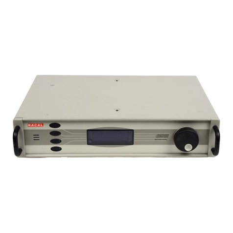
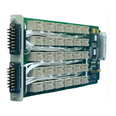
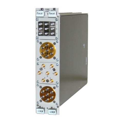
Racal Instruments 1260 User manual

-~
ARTISAN
®
~I
TECHNOLOGY
GROUP
Your definitive source
for
quality
pre-owned
equipment.
Artisan Technology
Group
Full-service,
independent
repair
center
with
experienced
engineers
and
technicians
on staff.
We
buy
your
excess,
underutilized,
and
idle
equipment
along
with
credit
for
buybacks
and
trade-ins
.
Custom
engineering
so
your
equipment
works
exactly as
you
specify.
•
Critical
and
expedited
services
•
Leasing
/
Rentals/
Demos
• In
stock/
Ready-to-ship
•
!TAR-certified
secure
asset
solutions
Expert
team
ITrust
guarantee
I
100%
satisfaction
All
tr
ademarks,
br
a
nd
names, a
nd
br
a
nd
s a
pp
earing here
in
are
th
e property of
th
e
ir
r
es
pecti
ve
ow
ner
s.
Find the Astronics / EADS / Racal Option 01 at our website: Click HERE

USER MANUAL
SERIES 1260
VXI SWITCHING CARDS
PUBLICATION NO. 980673-999
RACAL INSTRUMENTS
Racal Instruments, Inc.
4 Goodyear St., Irvine, CA 92618-2002
Tel: (800) RACAL-ATE, (800) 722-2528, (949) 859-8999; FAX: (949) 859-7139
Racal Instruments, Ltd.
480 Bath Road, Slough, Berkshire, SL1 6BE, United Kingdom
Tel: +44 (0) 1628 604455; FAX: +44 (0) 1628 662017
Racal Systems Electronique S.A.
18 Avenue Dutartre, 78150 LeChesnay, France
Tel: +33 (1) 3923 2222; FAX: +33 (1) 3923 2225
Racal Systems Elettronica s.r.l.
Strada 2-Palazzo C4, 20090 Milanofiori Assago, Milan, Italy
Tel: +39 (0)2 5750 1796; FAX +39 (0)2 5750 1828
Racal Elektronik System GmbH.
Technologiepark Bergisch Gladbach, Friedrich-Ebert-Strasse, D-51429 Bergisch Gladbach, Germany
Tel.: +49 2204 8442 00; FAX: +49 2204 8442 19
Racal Instruments, Ltd.
Unit 5, 25F., Mega Trade Center, No 1, Mei Wan Road, Tsuen Wan, Hong Kong, PRC
Tel: +852 2405 5500, FAX: +852 2416 4335
http://www.racalinstruments.com
PUBLICATION DATE: FEBRUARY 24, 2003
Copyright 2001 by Racal Instruments, Inc. Printed in the United States of America. All rights reserved.
This book or parts there of may not be reproduced in any form without written permission of the publisher.

Thank you for purchasing this Racal Instruments product.
For this product, or any other Racal Instruments product that incorporates software drivers, you
may access our web site to verify and/or download the latest driver versions. The web address for
driver downloads is:
http://www.racalinstruments.com/downloads
You will be asked to register one time only to gain access to the driver and product manual
downloads sections. At registration a cookie will be placed on your computer if you choose to
accept it. This is done to facilitate your use of these sections on future visits. You may refuse to accept the
cookie and still have complete access to the software driver database but will have to re-register every time
you visit. This cookie is for ease of use only and no information is gathered for, sold, or reported to, any third
party organization.
If you have any questions about software driver downloads or our privacy policy, please contact us at
WARRANTY STATEMENT
All Racal Instruments, Inc. products are designed and manufactured to exacting standards and in
full conformance to Racal’s ISO 9001 procedures.
This warranty does not apply to defects resulting from any modification(s) of any product or part
without Racal’s express written consent, or misuse of any product or part. The warranty also does
not apply to fuses, software, non-rechargeable batteries, damage from battery leakage, or problems
arising from normal wear, such as mechanical relay life, or failure to follow instructions.
This warranty is in lieu of all other warranties, expressed or implied, including any implied warranty
of merchantability or fitness for a particular use. The remedies provided herein are buyer’s sole and
exclusive remedies.
For the specific terms of your standard warranty, or optional extended warranty or service
agreement, contact your Racal customer service advisor. Please have the following information
available to facilitate service.
1. Product serial number
2. Product model number
3. Your company and contact information
You may contact your customer service advisor by:
E-Mail: Helpdesk@racalinstruments.com
Telephone: +1 800 722 3262 (USA)
+44(0) 8706 080134 (UK)
+852 2405 5500 (Hong Kong)
Fax: +1 949 859 7309 (USA)
+44(0) 1628 662017 (UK)
+852 2416 4335 (Hong Kong)

RETURN of PRODUCT
Authorization is required from Racal Instruments before you send us your product for service or
calibration. Call your nearest Racal Instruments support facility. A list is located on the last page of
this manual. If you are unsure where to call, contact Racal Instruments, Inc. Customer Support
Department in Irvine, California, USA at 1-800-722-3262 or 1-949-859-8999 or via fax at 1-949-859-
PROPRIETARY NOTICE
This document and the technical data herein disclosed, are proprietary to Racal Instruments, and
shall not, without express written permission of Racal Instruments, be used, in whole or in part to
solicit quotations from a competitive source or used for manufacture by anyone other than Racal
Instruments. The information herein has been developed at private expense, and may only be used
for operation and maintenance reference purposes or for purposes of engineering evaluation and
incorporation into technical specifications and other documents which specify procurement of
products from Racal Instruments.
DISCLAIMER
Buyer acknowledges and agrees that it is responsible for the operation of the goods purchased
and should ensure that they are used properly and in accordance with this handbook and any
other instructions provided by Seller. RII products are not specifically designed, manufactured or
intended to be used as parts, assemblies or components in planning, construction, maintenance or
operation of a nuclear facility, or in life support or safety critical applications in which the failure of
the RII product could create a situation where personal injury or death could occur. Should Buyer
purchase RII product for such unintended application, Buyer shall indemnify and hold RII, its
officers, employees, subsidiaries, affiliates and distributors harmless against all claims arising out
of a claim for personal injury or death associated with such unintended use.

FOR YOUR SAFETY
Before undertaking any troubleshooting, maintenance or exploratory procedure, read carefully the
WARNINGS and CAUTION notices.
This equipment contains voltage hazardous to human life and safety, and is capable of inflicting
personal injury.
If this instrument is to be powered from the AC line (mains) through an autotransformer, ensure the
common connector is connected to the neutral (earth pole) of the power supply.
Before operating the unit, ensure the conductor (green wire) is connected to the ground (earth)
conductor of the power outlet. Do not use a two-conductor extension cord or a three-prong/two-
prong adapter. This will defeat the protective feature of the third conductor in the power cord.
Maintenance and calibration procedures sometimes call for operation of the unit with power applied
and protective covers removed. Read the procedures and heed warnings to avoid “live” circuit
points.
Before operating this instrument:
1. Ensure the instrument is configured to operate on the voltage at the power source. See
Installation Section.
2. Ensure the proper fuse is in place for the power source to operate.
3. Ensure all other devices connected to or in proximity to this instrument are properly grounded or
connected to the protective third-wire earth ground.
If the instrument:
- fails to operate satisfactorily
- shows visible damage
- has been stored under unfavorable conditions
- has sustained stress
Do not operate until performance is checked by qualified personnel.


This page was left intentionally blank.

1260 Series User Manual
i
Table of Contents
Chapter 1
GENERAL INFORMATION ........................................................................................................... 1-1
Introduction ............................................................................................................................... 1-1
General Information................................................................................................................... 1-1
Options...................................................................................................................................... 1-3
Option 01 ............................................................................................................................... 1-3
Chapter 2
INSTALLATION INSTRUCTIONS ................................................................................................. 2-1
Introduction ............................................................................................................................... 2-1
Unpacking and Inspection ......................................................................................................... 2-1
Reshipment Instructions ............................................................................................................ 2-1
Option 01 Installation................................................................................................................. 2-1
Interrupt Level and Logical Address Setting (1260-01 - Equipped Modules Only) .................. 2-4
Switching Module Address Setting (All Modules) ................................................................... 2-5
Local Bus Daisychaining ........................................................................................................ 2-6
LBUS Lockout Keys ...............................................................................................................2-7
Switching Module Chassis Installation ................................................................................... 2-9
Chapter 3
OPERATION................................................................................................................................. 3-1
Introduction ............................................................................................................................... 3-1
Input Format.............................................................................................................................. 3-1
Output Format ........................................................................................................................... 3-1
1260-01 Device Dependant Command Codes ....................................................................... 3-3
CLOSE ............................................................................................................................... 3-3
CNF.................................................................................................................................... 3-3
DLY .................................................................................................................................... 3-3
EOI..................................................................................................................................... 3-4
EQU ................................................................................................................................... 3-5
EXCL.................................................................................................................................. 3-6
OPEN................................................................................................................................. 3-6
PDATAOUT........................................................................................................................3-8
PSETUP........................................................................................................................... 3-10
PUPRCL........................................................................................................................... 3-11
READ ............................................................................................................................... 3-11
RECALL ........................................................................................................................... 3-11

1260 Series User Manual
ii
RESET............................................................................................................................. 3-11

SCAN............................................................................................................................... 3-12
SETUP............................................................................................................................. 3-12
SLIST............................................................................................................................... 3-13
SRQMASK ....................................................................................................................... 3-14
STORE ............................................................................................................................ 3-15
SYNC............................................................................................................................... 3-16
TEST................................................................................................................................ 3-16
TTLTRG........................................................................................................................... 3-17
YERR............................................................................................................................... 3-17
Chapter 4
THEORY OF OPERATION........................................................................................................... 4-1
Introduction ............................................................................................................................... 4-1
Functional Blocks ...................................................................................................................... 4-1
Theory of Operation .................................................................................................................. 4-3
Power Suppliers .................................................................................................................... 4-3
Microprocessor Block ............................................................................................................4-3
The Reset Circuits ................................................................................................................. 4-4
VXI Interface.......................................................................................................................... 4-5
The Lbus Interface .................................................................................................................... 4-6
Chapter 5
DRAWINGS.................................................................................................................................. 5-1
Chapter 6
PARTS LISTS............................................................................................................................... 6-1
Chapter 7
Product Support ........................................................................................................................ 7-1
Reshipment Instructions............................................................................................................ 7-1
Support Offices ......................................................................................................................... 7-2

1260 Series User Manual
iii
List of Figures
Figure 1-1, 1260 Series Switch Module......................................................................................... 1-1
Figure 1-2, 1260 Series Smart Card and Slaves ........................................................................... 1-2
Figure 2-1, 1260-01 Smart Card ................................................................................................... 2-2
Figure 2-2, Switching Module Connector and Switch Location ...................................................... 2-2
Figure 2-3, 1260-40 Switch, Connector and Jumper Location ....................................................... 2-3
Figure 2-4, S1 Switch Function ..................................................................................................... 2-5
Figure 2-5, 1260 Series Master and Slave LBUS Interconnections ............................................... 2-6
Figure 2-6 LBUS Lockout Keys..................................................................................................... 2-7
Figure 2-7, 1260 Series Master/Slave Configuration ..................................................................... 2-8
Table 3-1, 1260 Option 01 Status Byte ....................................................................................... 3-15
Table 3-2, 1260 Series Error Codes............................................................................................ 3-17
Figure 4-1, 1260 Smart Card Block Diagram................................................................................. 4-2
Figure 4-2, 1260 Microprocessor Block Diagram........................................................................... 4-2

1260 Series User Manual
iv

1260 Series User Manual
General Information 1-1
Chapter 1
GENERAL INFORMATION
Introduction This manual provides the information necessary to install one or
more of the Racal Instruments 1260 Series switching modules in a
VXIbus compatible chassis, and to operate the switching modules
correctly.
General
Information
The 1260 switching modules are a range of C size, VXIbus
compatible switching modules that provide switching for
microwave, RF, audio, high voltage, high current, low level and
video applications. The modules are configured as matrices,
multiplexers, switching trees, SPDTs and DPDTs. Refer to Figure
1-1 which shows a 1260 Switch Module in a VXIbus chassis.
Figure 1-1, 1260 Series Switch Module
VXI CHASSIS
SWITCH MODULE
CAPTIVE
SCREWS FRONT
PAN EL
P1CONNECTOR
P2CONNECTOR
CARD GUIDES

1260 Series User Manual
General Information 1-2
The switching modules are installed in a VXIbus compatible
chassis in a continuous set of adjacent chassis slots. One of the
modules to be fitted to the chassis must be designated the system
Master, and must be fitted with Option 01. All other modules are
slaved to the master. Refer to Figure 1-2 which shows the smart
card and slaves.
The module fitted with Option 01 must be fitted in the leftmost
chassis slot that is to contain a switching module. If only one
module is to be fitted to the chassis, several jumper wires must be
removed from, or DIP switches opened on, the switching module.
If more than one module is to be fitted to the chassis, these
jumpers must be removed from (or the DIP switches opened) the
module in the rightmost chassis position containing a switching
module.
NOTE
If you are using seven or more 1260 series modules,
you must add a termination jumper to the module on
the far right See Chapter 2.
Two separate addresses are required in the use of a 1260
switching system. The first is the VXIbus specification defined
logical address used by the chassis Resource Manager and the
second, the card address, is an address used by the 1260 Master
to control the cards slaved to it. The card address is used in the
device dependant commands used to control the switching
modules. The logical address is set by a DIP switch on the 1260-
01 Smart Card, and the card addresses are set by a DIP switch on
the switching module PCB.
Figure 1-2, 1260 Series Smart Card and Slaves
P1
P2
LBUS
VXIBUS
BACKPLANE
SMART CARD
1260 SERIES
MASTER
SLAVE
SLAVE

1260 Series User Manual
General Information 1-3
Options
Option 01 The Option 01 Smart Card (Master) is required for use in all 1260
switching systems. This option acts as the switching system
master, and all other switching modules are slaved to it. It turns
any number of modules into a message-based VXIbus switching
system.
The smart card is addressed over the VXIbus, and all other
modules resident in the VXIbus chassis are controlled by this card.
Option 01 uses the local bus on the VXI P2 connector to provide
scanning, delay and exclude capabilities.
The built-in-test features in the smart card include confidence
checking which monitors the state of each relay. It monitors a
spare set of contacts or sensing coil current to ensure the
switching system configuration is as programmed.
Refer to Section 2 for software installation procedures for the
1260-01, and to Section 3 for the software command set used to
control the switching modules. The sections on individual modules
describe the device specific installation and programming for each
module.

1260 Series User Manual
General Information 1-4
This page was left intentionally blank.

1260 Series User Manual
Installation Instructions 2-1
Chapter 2
INSTALLATION INSTRUCTIONS
Introduction This section describes the unpacking and inspection, reshipment,
installation and environmental requirements of the 1260 Series
switching modules.
Unpacking and
Inspection
Prior to unpacking the switching module, check the exterior of the
shipping carton for any signs of damage. All irregularities should
be noted on the shipping bill. Remove the instrument from the
carton, preserving the factory packaging as much as possible.
Inspect the switching module for any defect or damage.
Immediately notify the carrier if any damage is apparent. Before
use, have qualified personnel perform a safety check.
Reshipment
Instructions
Use the original packaging when returning the switching module to
Racal Instruments for calibration or servicing. The shipping carton
and packaging will provide the necessary support for safe
reshipment. If the original packaging is unavailable, wrap the
switching module in plastic sheeting and use plastic spray foam to
surround and protect the instrument. Reship in the original or a
new shipping carton.
Option 01
Installation
To install Option 01 to a 1260 switching module, carry out the
following procedure.
Remove the module top and bottom covers.
Remove the jumper board (Racal Instruments P/N 401951) fitted to
connector J4 on the switching module. Note the 1260-40 has
jumpers installed in the J4 connector that must be removed.
Remove the jumper board (Racal Instruments P/N 401951-003)
fitted to connector J3 on the switching module.
Align the 1260-01 card with the switching module, P3 to J3, P4 to
J4, and press the 1260-01 and the module firmly together to mate

1260 Series User Manual
Installation Instructions 2-2
the P3 and P4 connectors, taking care not to bend or damage any
pins on the mating connectors. Refer to Figures 2-2 and 2-3 for the
location of J3 and J4. Secure the 1260-01 card to the module with
the fasteners provided at the three standoff positions on the 1260-
01.
Figure 2-1, 1260-01 Smart Card
Figure 2-2, Switching Module Connector and Switch Location

1260 Series User Manual
Installation Instructions 2-3
Figure 2-3, 1260-40 Switch, Connector and Jumper Location
The 1260 Master is fitted with the VXIbus defined SYSFAIL LED.
To install the LED, connect the cable supplied to the 3-pin plug in
the Option 01 PCB. The cable and plug are configured to achieve
correct operation either way the cable is connected at the end. The
LED is inserted into the hole marked FAIL at the top of the module
front panel from the outside of the module so the LED pins point
into the module. The cable supplied is fitted with a 2-pin connector
at the LED end, and is polarized to ensure correct installation.
Proceed to Subsection 2.5 to set the interrupt level and logical
address of the Option 01.

1260 Series User Manual
Installation Instructions 2-4
Interrupt Level
and Logical
Address Setting
(1260-01 -
Equipped
Modules Only)
If not previously done, remove the module's top cover. To set the
1260-01 logical address, set switch SW1 on the 1260-01 board to
the binary equivalent of the logical address selected. For SW1, a
switch in the OFF position corresponds to binary 1, and the ON
position corresponds to binary 0. Switch 1 on SW1 corresponds to
the most significant digit, and switch 8 corresponds to the least
significant digit. Logical addresses in the range 0 to 255 are
permitted. Refer to Figure 2-1 for the location of SW1.
NOTE
The 1260-01 logical address is set to 15 by Racal
Instruments before shipment.
All switching modules resident in a VXIbus chassis must have
unique addresses. Incorrect operation of the system will result if
two or more modules are set to the same module address.
To set the 1260-01 interrupt level, set switches 1, 2 and 3 on SW2
on the 1260-01 board to the binary equivalent of the interrupt level
selected. For SW2, a switch in the OFF position corresponds to
binary 1, and the ON position corresponds to binary 0. Switch 1 on
SW2 corresponds to the least significant bit, and switch 3
corresponds to the most significant bit. Interrupt levels in the range
0 to 7 are permitted. Switch 4 is not used. Refer to Figure 2-1 for
the location of SW2.
NOTE
The 1260-01 interrupt level is set to 2 by Racal
Instruments before shipment.
Replace the module covers. Replacement is the reverse of the
removal procedure.
NOTE
Any 1260 switching card may have Option 01 fitted
and be designated as the Master.

1260 Series User Manual
Installation Instructions 2-5
Switching Module
Address Setting
(All Modules)
To set a module address, carry out the following procedure.
For the 1260-40 only, remove the module covers.
Set switch SW1 on the module to the binary equivalent of the
address. Switches 1 to 4 are used to set the module address, with
switch 4 the least significant bit, and switch 1 the most significant.
The OFF positions for SW1 correspond to binary 0, and ON
positions correspond to binary 1. Addresses in the range 1 to 12
are permitted. Refer to Figure 2-2 for the location of SW1 on the
switching module PCB, or to Figure 2-3 for the location of SW1 on
the 1260-40. The functions of the various S1 switches are shown
in Figure 2-4.
Figure 2-4, S1 Switch Function
NOTE
The address set at switch SW1 on the switching
module controls the value of the card address the
switching module will respond to. The OPEN and
CLOSE statements using the card address are
specified in Section 4.4. Example: For a module to
respond to the command CLOSE 5.1205, the address
of the module must be set to 5.
Several modules are capable of more than one configuration, and
respond to different command codes in their various
configurations. Switches 5 and 6 on SW1 are used to select the
command code sets these modules respond to. Refer to the
module specific sections for the procedure to set the switches for
each module.
For the 1260-40 only, replace the switching module covers.
Replacement is the reverse of the removal procedure.
Other manuals for 1260
5
This manual suits for next models
2
Table of contents
Other Racal Instruments Switch manuals

Racal Instruments
Racal Instruments 1260-82 User manual

Racal Instruments
Racal Instruments 1260-22 User manual

Racal Instruments
Racal Instruments 1260-37 User manual

Racal Instruments
Racal Instruments 1260-X121 User manual

Racal Instruments
Racal Instruments 1256E User manual

Racal Instruments
Racal Instruments X Series User manual

Racal Instruments
Racal Instruments 1260 User manual

Racal Instruments
Racal Instruments 1256 User manual

Racal Instruments
Racal Instruments 1260-100 User manual