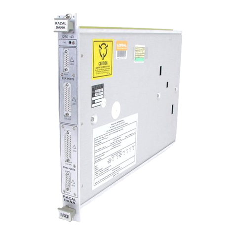
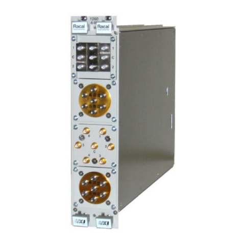
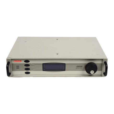
Racal Instruments X Series User manual

X-Series ADAPT-a-SWITCH
CARRIER MODULE
MODEL 1260-100X
PUBLICATION NO. 980914-100X
RACAL INSTRUMENTS
United States
(Corporate Headquarters and Service Center)
4 Goodyear Street, Irvine, CA 92618
Tel: (800) 722-2528, (949) 859-8999; Fax: (949) 859-7139
5730 Northwest Parkway Suite 700, San Antonio, TX 78249
Tel: (210) 699-6799; Fax: (210) 699-8857
Europe
(European Headquarters and Service Center)
18 Avenue Dutartre, 78150 LeChesnay, France
Tel: +33 (0)1 39 23 22 22; Fax: +33 (0)1 39 23 22 25
29-31 Cobham Road, Wimborne, Dorset BH21 7PF, United Kingdom
Tel: +44 (0) 1202 872800; Fax: +44 (0) 1202 870810
Via Milazzo 25, 20092 Cinisello B, Milan, Italy
Tel: +39 (0)2 6123 901; Fax: +39 (0)2 6129 3606
Racal Instruments Group Limited, Technologie Park, D-51429 Bergisch Gladbach, Germany
Tel: +49 2204 844205; Fax: +49 2204 844219
http://www.racalinstruments.com
www.racalinstruments.de
PUBLICATION DATE: November 23, 2005
Copyright 2005 by Racal Instruments, Inc. Printed in the United States of America. All rights reserved.
This book or parts thereof may not be reproduced in any form without written permission of the publisher.

THANK YOU FOR PURCHASING THIS RACAL INSTRUMENTS PRODUCT.
For this product, or any other Racal Instruments product that incorporates software drivers, you may access
our web site to verify and/or download the latest driver versions. The web address for driver downloads is:
http://www.racalinstruments.com/downloads
If you have any questions about software driver downloads or our privacy policy, please contact us at
WARRANTY STATEMENT
All Racal Instruments, Inc. products are designed and manufactured to exacting standards and in full
conformance to Racal’s ISO 9001:2000 processes.
This warranty does not apply to defects resulting from any modification(s) of any product or part without Racal
Instruments express written consent, or misuse of any product or part. The warranty also does not apply to
fuses, software, non-rechargeable batteries, damage from battery leakage, or problems arising from normal
wear, such as mechanical relay life, or failure to follow instructions.
This warranty is in lieu of all other warranties, expressed or implied, including any implied warranty of
merchantability or fitness for a particular use. The remedies provided herein are buyer’s sole and exclusive
remedies.
For the specific terms of your standard warranty, or optional extended warranty or service agreement, contact
your Racal customer service advisor. Please have the following information available to facilitate service.
1. Product serial number
2. Product model number
3. Your company and contact information
You may contact your customer service advisor by:
E-Mail: [email protected]
Telephone: +1 800 722 3262 (USA)
+44(0) 8706 080134 (UK)
Fax: +1 949 859 7309 (USA)
+44(0) 1628 662017 (UK)

RETURN of PRODUCT
Authorization is required from Racal Instruments before you send us your product for service or calibration.
Call your nearest Racal Instruments support facility. A list is located on the last page of this manual. If you are
unsure where to call, contact Racal Instruments, Inc. Customer Support Department in Irvine, California, USA
at 1-800-722-3262 or 1-949-859-8999 or via fax at 1-949-859-7139. We can be reached at:
PROPRIETARY NOTICE
This document and the technical data herein disclosed, are proprietary to Racal Instruments, and shall not,
without express written permission of Racal Instruments, be used, in whole or in part to solicit quotations from
a competitive source or used for manufacture by anyone other than Racal Instruments. The information
herein has been developed at private expense, and may only be used for operation and maintenance
reference purposes or for purposes of engineering evaluation and incorporation into technical specifications
and other documents which specify procurement of products from Racal Instruments.
DISCLAIMER
Buyer acknowledges and agrees that it is responsible for the operation of the goods purchased and should
ensure that they are used properly and in accordance with this handbook and any other instructions provided
by Seller. Racal Instruments products are not specifically designed, manufactured or intended to be used as
parts, assemblies or components in planning, construction, maintenance or operation of a nuclear facility, or
in life support or safety critical applications in which the failure of the Racal Instruments product could create
a situation where personal injury or death could occur. Should Buyer purchase Racal Instruments product for
such unintended application, Buyer shall indemnify and hold Racal Instruments, its officers, employees,
subsidiaries, affiliates and distributors harmless against all claims arising out of a claim for personal injury or
death associated with such unintended use.

FOR YOUR SAFETY
Before undertaking any troubleshooting, maintenance or exploratory procedure, read carefully the
WARNINGS and CAUTION notices.
This equipment contains voltage hazardous to
human life and safety, and is capable of
inflicting personal injury.
If this instrument is to be powered from the AC line (mains) through an auto-
transformer, ensure the common connector is connected to the neutral (earth pole)
of the power supply.
Before operating the unit, ensure the conductor (green wire) is connected to the
ground (earth) conductor of the power outlet. Do not use a two-conductor extension
cord or a three-prong/two-prong adapter. This will defeat the protective feature of the
third conductor in the power cord.
Maintenance and calibration procedures sometimes call for operation of the unit with
power applied and protective covers removed. Read the procedures and heed
warnings to avoid “live” circuit points.
Before operating this instrument:
1. Ensure the proper fuse is in place for the power source to operate.
2. Ensure all other devices connected to or in proximity to this instrument are properly grounded or
connected to the protective third-wire earth ground.
If the instrument:
- fails to operate satisfactorily
- shows visible damage
- has been stored under unfavorable conditions
- has sustained stress
Do not operate until, performance is checked by qualified personnel.

1260-100X User Manual
i
Table of Contents
Chapter 1...............................................................................................................................1-1
OVERVIEW......................................................................................................................................1-1
Items Shipped with 1260-100X.....................................................................................................1-1
Part Numbers, Options and Ordering Information .......................................................................1-1
Functional Description..................................................................................................................1-2
Features.......................................................................................................................................1-3
Compatibility with Racal Instruments 1260-Series ...................................................................1-3
Ease of Use..............................................................................................................................1-4
Maintainability...........................................................................................................................1-4
Dynamically-Configured Analog Bus........................................................................................1-5
Chapter 2...............................................................................................................................2-1
GETTING STARTED .......................................................................................................................2-1
Unpacking and Inspection............................................................................................................2-1
Reshipment Instructions...............................................................................................................2-1
Option-01T ...................................................................................................................................2-2
Setting Configuration Switches ....................................................................................................2-4
Local Bus Daisy-Chain Switches..............................................................................................2-5
Module Address Switch................................................................................................................2-5
Inserting and Removing Plug-Ins .................................................................................................2-6
Installing the 1260-100X into a VXIbus Chassis ..........................................................................2-6
Making Connections to Plug-Ins (Pin-Outs) .................................................................................2-7
Power-On Self-Test......................................................................................................................2-7
Closing and Opening Relays........................................................................................................2-8

1260-100X User Manual
ii
Chapter 3...............................................................................................................................3-1
USING THE 1260-100X...................................................................................................................3-1
Checking the Response of Plug-Ins.............................................................................................3-1
Closing and Opening Relays........................................................................................................3-1
Emergency Reset Function..........................................................................................................3-2
Description................................................................................................................................3-2
Interface....................................................................................................................................3-2
Normal State of External Switch...............................................................................................3-2
Scope of Reset Event...............................................................................................................3-3
Sequence of Events .................................................................................................................3-3
Chapter 4...............................................................................................................................4-1
MAINTENANCE...............................................................................................................................4-1
Performance Verification Procedure ............................................................................................4-1
Purpose....................................................................................................................................4-1
Equipment Required.................................................................................................................4-1
Software Required....................................................................................................................4-2
Procedure.................................................................................................................................4-2
Chapter 5...............................................................................................................................5-1
PRODUCT SUPPORT.....................................................................................................................5-1
Product Support ...........................................................................................................................5-1
Warranty.......................................................................................................................................5-1
Support Offices.............................................................................................................................5-2

1260-100X User Manual
iii
AppendixA...........................................................................................................................A-1
1260-100X SPECIFICATIONS........................................................................................................A-1
General........................................................................................................................................A-1
Mechanical ..............................................................................................................................A-1
Electrical..................................................................................................................................A-1
Power and Cooling ..................................................................................................................A-2
Environmental..........................................................................................................................A-2
EMC and Safety.......................................................................................................................A-2
Reliability .................................................................................................................................A-2
AppendixB...........................................................................................................................B-1
1260-100X THEORY OF OPERATION ..........................................................................................B-1
General........................................................................................................................................B-1
VXI Interface PCB Subassembly.................................................................................................B-1
Power Filtering.........................................................................................................................B-1
Signal Connections..................................................................................................................B-2
OPTION-01T/Passport PCB Subassembly .............................................................................B-2
Backplane/ Mezzanine PCB Subassembly..........................................................................B-2
Local Bus Signal Routing ........................................................................................................B-3
Reset Circuit............................................................................................................................B-3
Interrupt ...................................................................................................................................B-3
Communications......................................................................................................................B-4
PLD Programming Connector..................................................................................................B-5

1260-100X User Manual
iv
AppendixC..........................................................................................................................C-1
TROUBLESHOOTING....................................................................................................................C-1
Introduction..................................................................................................................................C-1
Troubleshooting Table.................................................................................................................C-1
Communications Troubleshooting...........................................................................................C-2
List of Figures
Figure 1-1, The 1260-100X Shown with Two X-series Adapt-a-Switch Cards Installed..................1-2
Figure 1-2, Ease-of-Use Features ...................................................................................................1-5
Figure 2-1, The Front View –Two Carriers Configuration................................................................2-2
Figure 2-2, 1260-100X Configuration Switches...............................................................................2-4

1260-100X User Manual
Racal Instruments ©2005 Overview 1-1
Chapter 1
OVERVIEW
ITEMS SHIPPED
WITH 1260-100X The following items are shipped with each 1260-100X Adapt-a-
Switch Carrier:
ITEM RACAL PART
NUMBER QUANTITY
Retaining Plate, Top 457383-001 1
Retaining Plate,
Middle 457383-003 1
Retaining Plate,
Bottom 457383-002 1
Blanking plate 457403 1
Instruction manual 980914-100X 1
The following accessories may be ordered separately:
Blanking Plate 457403 1
EMI Shield 457376 1
Retaining Plate, Top 457383-001 1
Retaining Plate,
Middle 457383-003 1
Retaining Plate,
Bottom 457383-002 1
PART NUMBERS,
OPTIONS AND
ORDERING
INFORMATION
The 1260-100X can be ordered as an assembly or as individual
pieces as needed depending upon the application. The following
Part Numbers are available as standard products:
408007
Includes: 408034 1260-100X Enclosure Assembly
4408035-100X Shipping Kit

1260-100X User Manual
Overview 1-2 Racal Instruments ©2005
Figure 1-1, The 1260-100X Shown with Two X-series Adapt-a-Switch Cards Installed
FUNCTIONAL
DESCRIPTION The 1260-100X Adapt-a-Switch Carrier (currently without Option
01T) is a two-slot VXI bus module that may contain up to six X-
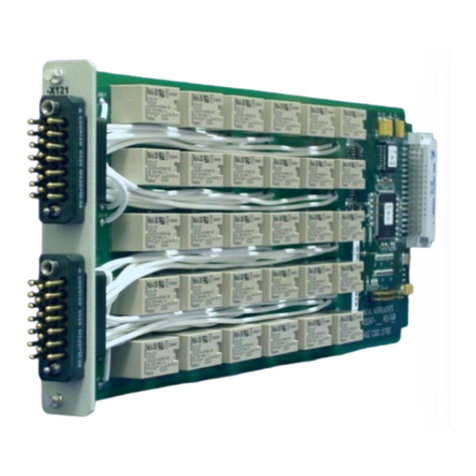
series Adapt-a-Switch plug-in cards. The X-series Adapt-a-Switch
cards are 3.3” longer and 0.4” wider than the non X-series cards,
thus allowing higher density relay configurations.
You may leave some slots unoccupied for future expansion.
Each plug-in has its own unique configuration of relays or digital
testing capabilities, such as:

1260-100X User Manual
Racal Instruments ©2005 Overview 1-3
• Switch, for connecting individual pairs of inputs together.
• Multiplexer (MUX), for connecting one input to any one of
several outputs.
• Matrix. A matrix has two groups of channels: a row and a
column. The matrix can connect any row channel to any
column channel. The matrix may make multiple independent
connections at the same time.
• RF switch, for switching radio-frequency signals via
impedance-matched signal paths.
• Digital I/O, for a wide range of digital test applications.
Features
Compatibility
with Racal
Instruments 1260-
Series
Functionally, it is identical to the 1260-100 but currently without an
Option-01T. It only accepts the X-series Adapt-a-Switch plug-in
cards. The 1260-100X Adapt-a-Switch Carrier is controlled by the
same Option-01T controller installed in another carrier in the same
group as conventional Racal Instruments 1260-Series switch
modules. A single Option-01T Switch Controller Module may
control up to twelve switch modules or plug-ins. This may include
a combination of 1260-Series and Adapt-a-Switch plug-ins.
See Chapter 2: Getting Started for instructions on combining
1260-Series modules and Adapt-a-Switch plug-ins in the same
VXIbus chassis.

1260-100X User Manual
Overview 1-4 Racal Instruments ©2005
Ease of Use The 1260-100X includes several ease-of-use features (the 1260-
100X model is shown in Figure 1-2):
• Plug-ins are easy to insert and extract from the front panel of
the 1260-100X, even while it is installed in a chassis.
• For only the 1260-100X, module addresses, used to uniquely
identify each plug-in, are set by a single DIP switch that is
easily accessible from the back of the 1260-100X. See
Setting Configuration Switches in Chapter 2: Getting
Started for instructions.
• The 1260-100X ejector handles also function as injectors,
making it easy to install the carrier into a VXIbus chassis.
Maintainability Maintainability of the 1260-100X is enhanced by the fact that plug-
ins are removable from the front panel. This has the following
benefits:
• The mean time to repair (MTTR) is minimized, since the carrier
does not need to be disassembled or even removed from the
VXIbus chassis.
• The switch system may be easily upgraded in the field by
adding or changing plug-ins.
• Sparing is less costly and more flexible, since individual plug-
ins may be spared rather than the entire 1260-100X module.

1260-100X User Manual
Racal Instruments ©2005 Overview 1-5
Figure 1-2, Ease-of-Use Features
Dynamically-
Configured
Analog Bus
The 1260-100X Adapt-a-Switch Carrier offers an analog bus to
interconnect two or more plug-ins. This allows the creation of
large multiplexers and matrices. The analog bus may be
dynamically configured under software control.
For instructions in using the analog bus, refer to the instruction
manuals for the individual multiplexer and matrix plug-ins.

1260-100X User Manual
Overview 1-6 Racal Instruments ©2005
This page was left intentionally blank.

1260-100X User Manual
Racal Instruments ©2005 Getting Started 2-1
Chapter 2
GETTING STARTED
Unpacking and
Inspection
1. Before unpacking the switching module, check the
exterior of the shipping carton for any signs of damage.
All irregularities should be noted on the shipping bill and
reported.
2. Remove the instrument from its carton, preserving the
factory packaging as much as possible.
3. Inspect the switching module for any defects or damage.
Immediately notify the carrier if any damage is apparent.
4. Have a qualified person check the instrument for safety
before use.
Reshipment
Instructions 1. Use the original packing material when returning the
switching module to Racal Instruments for servicing. The
original shipping carton and the instrument’s plastic foam
will provide the necessary support for safe reshipment.
2. If the original packing material is unavailable, wrap the
switching module in an ESD Shielding bag and use plastic
spray foam to surround and protect the instrument.
3. Reship in either the original or a new shipping carton.

1260-100X User Manual
Getting Started 2-2 Racal Instruments ©2005
1260-100 1260-100X
w/Option-01T
Figure 2-1, The Front View –Two Carriers Configuration.
Option-01T Presently, the 1260-100X can be used only as a compatible 1260-
type carrier adjacent to a 1260-100 module with an Option 01-T
card installed, or as one of the several 1260-Series modules in
consecutive slots.
The following rules apply when using the Option-01T controller:
1. Each Adapt-a-Switch or full-size VXI switch module has
its own unique module address.
2. Model 1260-100 assigns module addresses 1 through
12, to its module slot, depending on the position of the
Address Range DIP switch.
3. To be controlled by a single Option-01T, a group of
switch modules and carriers must be installed in a
contiguous group of VXIbus chassis slots and the
Option-01T must be installed in the left-most module in
the group.

1260-100X User Manual
Racal Instruments ©2005 Getting Started 2-3
Below are some examples of possible configurations:
Example 1:
A single Option-01T may control all Adapt-a-Switch
plug-ins in one or two 1260-100X Carriers. When it
controls two carriers, the carriers must be in adjacent
slots in the VXIbus chassis, with the Option-01T-
equipped carrier in the left-most slot of the group.
A single Option-01T may control all Adapt-a-Switch
plug-ins in a 1260-101, a 1260-100, or a 1260-100X
Carriers. When it controls two carriers, the carriers must
be in adjacent slots in the VXIbus chassis, with the
Option-01T-equipped carrier in the left-most slot of the
group. A single option_01T will not control more than
one 1260-101.
Example 2:
A single Option-01T may control a group of 1260-Series
switch modules. The modules must be installed in a
contiguous group of slots in the VXIbus chassis. Figure
2-1 shows the configuration which the left most 1260-
100 carrier is with Option 01-T installed and one 1260-
100X carrier.
Example 3:
A single Option-01T may control a mixed group of
1260-Series switch modules and Adapt-a-Switch plug-
ins. The maximum number of items in each group is
twelve. Each 1260-100X carrier counts as six plug-ins
and each 1260-101 carrier counts as two plug-ins,
regardless of the quantity of plug-ins actually installed.
For instance, a single Option-01T may control the
following group:
•Slot 3:1260-54 RF Switch (conventional one-slot
VXI module), equipped with Option-01T
•Slots 4 and 5:1260-100 Adapt-a-Switch carrier,
containing three 1260-138 plug-ins and two
1260-150 RF switch plug-ins.
•Slot 6:1260-22 Power Switch (conventional one-
slot VXI module)
•Slot 7:1260-22 Power Switch

1260-100X User Manual
Getting Started 2-4 Racal Instruments ©2005
•Slot 8: 1260-101 Adapt-a-Switch carrier,
containing one 1260-145.
The above group counts as eleven items: the 1260-54 and
1260-22 modules count as one item each, for a total of
three. The 1260-100X carrier is considered as six items,
regardless of the number of plug-ins installed. The 1260-
101 carrier is considered as two items. Adding these
together, the total number of controlled items is eleven.
This means that there is still room to add one 1260-Series
switch modules to the group, with the entire group
controlled by one Option-01T. The Option-01T must be
installed in the 1260-54 module in slot 3. In the case where
an Option-01T controls plug-ins residing in two adjacent
carriers, the Option-01T must be installed in the carrier on
the left.
For groups that are larger than twelve, additional
Option-01T modules are used.
Setting
Configuration
Switches
Model 1260-100X has its own configuration switches located
on the back panel (See Figure 2-2).
Figure 2-2, 1260-100X Configuration Switches

1260-100X User Manual
Racal Instruments ©2005 Getting Started 2-5
Set these switches as follows:
Local Bus Daisy-
Chain Switches
Currently, the 1260-100X requires another carrier with an Option-
01T installed in the adjacent left slot.
If you are using a 1260-100X Carrier as the last carrier in the VXI
chassis with no switch modules or carriers to its right, set all
twelve local bus daisy-chain switches to the OPEN position. On
the other hand, if you install a 1260-Series switch module or
another 1260-100X Carrier to the immediate right, set all twelve
local bus daisy-chain switches (S1 positions 1-6 and S2 positions
1-6) to the CLOSE position. This allows the Option-01T in the
carrier of the adjacent left slot to control not only the plug-ins in
that carrier, but the switch modules installed to the right, as well.
Module Address
Switch Although plug-ins and 1260-Series modules do not require logical
addresses (the Option-01T has one instead), they each have a
module address. The Option-01T uses module addresses to
distinguish between plug-ins, and between 1260-Series modules.
Each plug-in or module must have a unique module address from
one through twelve, inclusive. Models 1260-100X assigns
module addresses as follows:
1260-100X Module Address
The module address DIP switch S2 postion 7 (see figure 2-2)
sets the logical addresses for all plug-ins in the 1260-100X
Carrier. The switch has two settings:
•1-6 (opened) When the switch is set to this position, the
module addresses of the plug-ins are from
1 through 6, with 1 being in the left slot of
the top row. The plug-ins are addressed in
the following pattern:
•7-12 (closed) When the switch is set to this position, the
module addresses of the plug-ins are from
7 through 12, in the following pattern:

1260-100X User Manual
Getting Started 2-6 Racal Instruments ©2005
Inserting and
Removing Plug-
Ins
CAUTION
If the 1260-100X Carrier is in a VXIbus chassis, make
sure the chassis power is off before inserting or
removing plug-ins.
Use proper anti-static handling procedures when plug-
ins are outside the carrier.
Figure 1-2 shows how to insert or remove a plug-in. Prior to
inserting or removing a plug-in, the retaining plates have to be
removed. For examples, to insert or remove a plug-in in slots 1,
2, or 3, the top and middle retaining plates have to be removed.
To insert a plug-in in slots 4, 5, and 6, the middle and bottom
retaining plates have to be removed. To insert a plug-in, position
the module so that the edges align with the grooves in the carrier
slot. Slide the plug-in all the way into the carrier, then press
firmly to engage its connector with the carrier backplane.
Replace the plug-in retaining plates and tighten the screws
securely.
To remove a plug-in, remove the retaining plates as stated
previously to make them float freely. Since they are captive, they
do not come completely out. Pull firmly and evenly on the front
panel to disengage the plug-in from the backplane, then pull the
plug-in out of the carrier.
INSTALLING THE
1260-100X INTO A
VXIBUS CHASSIS
To install the 1260-100X Carrier into a VXIbus chassis, position the
carrier so that the ridges at the top and bottom align with the
grooves in the chassis slots (see Figure 1-3). As you push the
carrier into the chassis, ensure that the injector/ejector handles are
in the proper positions. The upper handle should be all the way
up, and the lower handle should be all the way down. Push the
carrier into the chassis until it stops. Then use the injector/ejector
handles to engage the carrier with the chassis backplane.
Simultaneously push the upper handle downward and the lower
handle upward until the carrier is fully inserted. Tighten the upper
and lower retaining screws.
This manual suits for next models
1
Table of contents
Other Racal Instruments Switch manuals

Racal Instruments
Racal Instruments 1256E User manual

Racal Instruments
Racal Instruments 1260-22 User manual

Racal Instruments
Racal Instruments 1260-100 User manual

Racal Instruments
Racal Instruments 1260-X121 User manual

Racal Instruments
Racal Instruments 1260 User manual

Racal Instruments
Racal Instruments 1260-82 User manual

Racal Instruments
Racal Instruments 1260 User manual

Racal Instruments
Racal Instruments 1256 User manual

Racal Instruments
Racal Instruments 1260-37 User manual