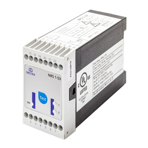
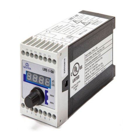
GESTRA LRS 1-50 User manual

EN (USA)
English
Conductivity Switch
LRS 1-50
Original Installation &
Operating Manual
850704-01

2LRS 1-50 - USA - Installation & Operating Manual - 850704-01
Contents
Content of this Manual......................................................................................................................... 4
Scope of supply, product package....................................................................................................... 4
How to use this Manual........................................................................................................................ 5
Illustrations and symbols used............................................................................................................ 5
Hazard symbols in this Manual............................................................................................................ 5
Types of warning .................................................................................................................................. 6
Specialist terms, abbreviations ........................................................................................................... 7
Usage for the intended purpose........................................................................................................... 8
Improper use ........................................................................................................................................ 8
Basic safety information ...................................................................................................................... 9
Required personnel qualifications..................................................................................................... 10
Notes on product liability................................................................................................................... 10
Function .............................................................................................................................................. 11
Technical data .................................................................................................................................... 12
Example rating plate/identification ................................................................................................... 13
Factory default settings ..................................................................................................................... 14
Dimensions of the LRS 1-50............................................................................................................... 15
Preparing for installation ................................................................................................................... 16
Installation.......................................................................................................................................... 17
In the control cabinet: Electrically connecting the conductivity switch.......................................... 18
Wiring diagram of conductivity switch LRS 1-50 ............................................................................ 18
Connecting the supply voltage ....................................................................................................... 19
Connecting the output contacts...................................................................................................... 19
Connecting conductivity electrode LRG 16-4.................................................................................. 19
Connecting conductivity electrode LRG 16-9.................................................................................. 19
In the plant: Electrically connecting the conductivity electrode ...................................................... 20
Connecting conductivity electrode LRG 16-4.................................................................................. 20
Connecting conductivity electrode LRG 16-9.................................................................................. 20
3LRS 1-50 - USA - Installation & Operating Manual - 850704-01
Contents
Changing the factory default settings ............................................................................................... 21
Changing the unit of measurement ................................................................................................ 21
Operating the conductivity switch..................................................................................................... 22
Meaning of codes on the 7-segment display.................................................................................. 22
Bringing into service .......................................................................................................................... 23
Setting parameters ........................................................................................................................ 23
Setting switchpoints and parameters ............................................................................................. 24
Operation, alarm and test................................................................................................................... 25
Password protection ...................................................................................................................... 26
Calibration ..................................................................................................................................... 27
Fault indications and troubleshooting............................................................................................... 28
Important notes .................................................................................................................................. 29
Action against high-frequency interference.................................................................................... 29
Taking out of service.......................................................................................................................... 30
Disposal .............................................................................................................................................. 30
UL components................................................................................................................................... 30
Declaration of Conformity
Standards and directives ................................................................................................................... 31

4LRS 1-50 - USA - Installation & Operating Manual - 850704-01
Content of this Manual
Product:
■ Conductivity Switch LRS 1-50
First edition:
BAN 850704-00/09-2021cm
© Copyright
All rights reserved. Any misuse, particularly reproduction and dissemination to third parties, is not
permitted. The General Terms & Conditions of GESTRA AG apply.
Scope of supply, product package
LRS 1-50
1 conductivity switch LRS 1-50
1 adhesive sign for ppm
1 Installation & Operating Manual

5LRS 1-50 - USA - Installation & Operating Manual - 850704-01
How to use this Manual
This Installation & Operating Manual describes the correct use of the LRS 1-50 conductivity switch.
It applies to persons who integrate this equipment in control systems, install, bring into service, op-
erate, maintain and dispose of this equipment. Anyone carrying out the above-mentioned activities
must have read this Installation & Operating Manual and understood its contents.
■ Read this Manual in full and follow all instructions.
■ Please also read the instructions for use of any accessories.
■ The Installation & Operating Manual is part of the product package. Keep it in an easily acces-
sible location.
Availability of this Installation & Operating Manual
■ Make sure this Installation & Operating Manual is always available to the operator.
■ If you pass on or sell the equipment to a third party, please also hand over the Installation &
Operating Manual.
Hazard symbols in this Manual
Danger zone, dangerous situation
Illustrations and symbols used
1. Action to be taken
2.
■ Lists
◆ Bullet points in lists
A Keys to illustrations
Additional
information
Read the relevant
Installation & Operating Manual

6LRS 1-50 - USA - Installation & Operating Manual - 850704-01
Types of warning
DANGER
Warning of a dangerous situation that results in death or serious injury.
WARNING
Warning of a dangerous situation that may possibly result in death or serious injury.
CAUTION
Warning of a situation that may result in minor or moderate injury.
ATTENTION
Warning of a situation that results in damage to property or the environment.

7LRS 1-50 - USA - Installation & Operating Manual - 850704-01
Specialist terms, abbreviations
Here, we explain some abbreviations, specialist terms, etc., which are used in this Manual.
NRGT .. / NRR.. / NRS.. / URS .. / URB .. / SRL .. / etc.
Equipment and type designations of GESTRA AG.
SELV
Safety Extra Low Voltage
Operating point (of the plant)
The operating point describes the operating parameters within which a plant or boiler is operated
in its nominal range. In a steam boiler, for example, these parameters would be output, pressure,
and temperature.
The design data may be a lot more stringent, however.
A boiler that is operated at 145psi (10bar) and 356°F (180°C) may be designed to withstand a
pressure of 870psi (60bar) and a temperature of 527°F (275°C), for example, which is therefore
not necessarily its operating point.

8LRS 1-50 - USA - Installation & Operating Manual - 850704-01
Usage for the intended purpose
The LRS 1-50 conductivity switch is used in combination with LRG 1.-.. conductivity electrodes
as a limit switch, e.g., in steam boilers and hot water installations or in condensate and feedwa-
ter tanks. The conductivity switch indicates when a MIN and MAX conductivity has been reached.
The LRS 1-50 is classified as an operating control in accordance with UL60730-1.
When used as intended, the LRS 1-50 conductivity switch can be combined in a circuit with the
LRG 16-4 and LRG 16-9 conductivity electrodes.
Improper use
There is a danger of death due to explosion if the equipment is used in potentially
explosive atmospheres.
Do not use the equipment in potentially explosive atmospheres.
Do not bring any equipment into service that does not have its own specific rating
plate.
The rating plate indicates the technical features of the equipment.

9LRS 1-50 - USA - Installation & Operating Manual - 850704-01
There is a risk of electric shock during work on electrical systems.
■ Always switch off the voltage to the plant before performing connection work.
■ Check that the plant is not carrying live voltage before commencing work.
Attempts to repair the equipment will cause the plant to become unsafe.
■ The LRS 1-50 conductivity switch may only be repaired by the manufacturer, GESTRA AG.
■ Only replace faulty equipment with identical equipment from GESTRA AG.
Basic safety information

10 LRS 1-50 - USA - Installation & Operating Manual - 850704-01
Required personnel qualifications
Activity Personnel
Integration in control system Specialist staff Plant designer
Installation/electrical connec-
tion/
bringing into service
Specialist staff
The equipment may only be installed, wired
and brought into service by qualified and
competent staff.
Operation Boiler service technician Staff trained by the plant operator.
Maintenance work Specialist staff
Fitting and maintenance work may only be
performed by authorized staff who have
undergone specific training.
Refits Specialist staff Persons trained by the plant operator to work
with pressure and temperature.
Notes on product liability
The manufacturer cannot accept any liability for damages resulting from improper use of the
equipment.

11LRS 1-50 - USA - Installation & Operating Manual - 850704-01
The LRS 1-50 conductivity switch, in conjunction with the LRG 1.-.. conductivity electrode,
measures conductivity in conductive fluids. The conductivity electrode used is the LRG 16-4
conductivity electrode, or the LRG 16-9 with integrated resistance thermometer for monitoring
the fluid temperature.
When the LRG 1.-.. conductivity electrode is connected, a reference measurement is taken and
a correction factor CF is adjusted to adapt the conductivity measurement to the specific condi-
tions of the installation.
When a resistance thermometer is connected, the temperature of the water is measured as well
as its conductivity. This enables the change in conductivity caused by rising water temperatures
to be compensated and based on the standardized reference temperature of 77°F
(25°C).
To do this, the temperature of the water is measured in the conductivity switch and the conduc-
tivity reading is automatically compensated as a function of the adjusted temperature coefficient
tC (%/°C). If the temperature changes, thanks to linear temperature compensation the reading is
referenced to 77°F (25°C) over the entire measuring range, and indicated as an actual value on
the 7-segment LED display.
The MIN/MAX limits can be varied as desired within the measuring range.
If the MIN or MAX limit is reached, the MIN or MAX output contact switches and the MIN or MAX
LED lights up. It switches back when the value is above or below the preset hysteresis.
Faults in the conductivity electrode or electrical connection and setting errors are shown on the
7-segment LED display. In the event of a malfunction, the MIN and MAX alarm is triggered.
If faults occur only in the LRS 1-50 conductivity switch, the MIN and MAX alarm is triggered and
the system is restarted.
Parameters can be changed and the MIN/MAX alarm simulated by turning the rotary knob.
Electrical conductivity is measured in µS/cm. In some countries, ppm (parts per million) is used as
well. Conversion 1 µS/cm = 0.5 ppm. You can set the conductivity switch to the required unit.
Safety information
The equipment may only be installed, wired and brought into service by qualified and competent
staff.
Fitting and maintenance work may only be performed by authorized staff who have undergone
specific training.
Function

12 LRS 1-50 - USA - Installation & Operating Manual - 850704-01
Technical data
Supply voltage
24 VDC +/– 20%; PELV / CLASS2
Fuse
External M0.5A (medium time-lag)
Power consumption
4 W
Connecting a conductivity electrode
1 input for LRG 16-4 conductivity electrode
(cell constant 1cm-1), 2-pole with shield,
1 input for LRG 16-9 conductivity electrode (cell constant 0.5cm-1), with integrated
resistance thermometer Pt100, 5-pole with shield.
Measuring voltage
0.8 Vss, pulse duty factor tv = 0.5, frequency 20-10000Hz.
Measuring range
1 to 10000μS/cm at 77°F (25°C) or 1 to 5000ppm at 77°F (25°C)
Switching hysteresis
MIN limit: + 3% of set MIN limit
MAX limit: – 3% of set MAX limit
Outputs
2 volt-free relay contacts, 8A 250V AC / 30V DC cos ϕ= 1.
Inductive loads must have interference suppression (RC combination) as specified by the
manufacturer.
Indicators and controls
1
rotary knob with integrated push-button for testing the MIN/MAX alarm and setting the
parameters,
1 4-digit 7-segment LED display,
2 red LEDs for MIN/MAX alarm,
1 4-pole code switch for configuration.
Terminal box
Terminal box material: base of black polycarbonate, front of gray polycarbonate
Wire size: 1 x AWG12 (4.0mm2) solid, or
1 x AWG14 (2.5mm2) stranded with sleeve acc. to DIN 46228 or
2 x AWG16 (1.5mm2) stranded with sleeve acc. to DIN 46228 [min. ∅0.004in (0.1mm)]
Terminal strips can be removed separately
Terminal box attachment: Mounting clip on support rail TH 35, EN 60715
Electrical safety
Pollution degree 2, overvoltage category II according to UL 60730-1
Protection
Terminal box: IP 40 according to EN 60529
Terminal strip: IP 20 according to EN 60529
As a UL open type, the equipment must be installed in a control cabinet.
Weight
Approx. 0.44 lb (0.2 kg)
Ambient temperature
at power-on 32° ... 131°F (0° … 55°C)
in operation 14° … 131°F (-10° … 55°C)
Transport temperature
-4° … 176°F (-20° … +80°C) (<100hours),
only switch on after a defrosting period of 24 hours.
Storage temperature
-4° … 158°F (-20° … +70°C), only switch on after a defrosting period of 24 hours.
Relative humidity
Max. 95%, non-condensing
Other information
Incorporated type 1 action operating control
Pollution degree 2, impulse voltage DC supply = 500V, AC output = 2500V

13LRS 1-50 - USA - Installation & Operating Manual - 850704-01
Leitfähigkeitsschalter
Conductivity Limit Switches
Commutateurs de valeurs
limites de conductibilité
MIN
MAX
Betriebsanleitung
beachten
See installation
instructions
Voir instructions de
montage
LRS 1-50
250V ~ T2.5A
IP (IP20)4040
GESTRA AG
Münchener Str.77
28215 Bremen
Made in Germany
Tamb = 55°C)T131°F (
1-5000ppm 1-10000µS/cm
LRG
Pt100
1..-..
+
_
M0.5A
4W +
1
2
3
4
6
7
8
5
_
24V
±20%
Input rating: 24VDC, 4W
Ambient temperature: 32-131°F (0-55°C)
Wiring: Use Copper Conductors Only,
Use 60/75°C Conductors,
Use No.18 16 AWG Wire Size Only,
Tightening: Torque 0.79Nm or 7lb in.
-
Use with accessory: LRG 16-4, LRG 16-9
OPERATING CONTROL
E513189
Output rating : Pilot duty B300 / R300
LRS 1-50
Rating plate, top
Safety
information
Output
contacts
Ambient
temperature
Type
designation
Manufacturer
Supply
voltage
Fuse,
provided by
customer
Power
consumption
Disposal
information
Connection
for conductivity
electrode
Measuring
range
External fuse
for output contacts
Protection
Rating plate, bottom
Fig. 1
Example rating plate/identification
Leitfähigkeitsschalter
Conductivity Limit Switches
Commutateurs de valeurs
limites de conductibilité
MIN
MAX
Betriebsanleitung
beachten
See installation
instructions
Voir instructions de
montage
LRS 1-50
250V ~ T2.5A
IP (IP20)4040
GESTRA AG
Münchener Str.77
28215 Bremen
Made in Germany
Tamb = 55°C)T131°F (
1-5000ppm 1-10000µS/cm
LRG
Pt100
1..-..
+
_
M0.5A
4W +
1
2
3
4
6
7
8
5
_
24V
±20%
Input rating: 24VDC, 4W
Ambient temperature: 32-131°F (0-55°C)
Wiring: Use Copper Conductors Only,
Use 60/75°C Conductors,
Use No.18 16 AWG Wire Size Only,
Tightening: Torque 0.79Nm or 7lb in.
-
Use with accessory: LRG 16-4, LRG 16-9
OPERATING CONTROL
E513189
Output rating : Pilot duty B300 / R300
LRS 1-50

14 LRS 1-50 - USA - Installation & Operating Manual - 850704-01
Factory default settings
DANGER
There is a risk of electric shock during work on electrical systems.
■ Switch off the voltage to the plant before you install the equipment.
■ Check that the plant is not carrying live voltage before commencing work.
Conductivity Switch LRS 1-50
■MAX switchpoint AL.Hi = 3000ppm (6000µS/cm)
■MIN AL.Lo = 250ppm (500µS/cm)
■ Switching hysteresis: +/– 3% (factory default)
■ Correction factor CF: 1
■
Temperature compensation inP: No
■ Temperature coefficient tC: 2.1% / °C
■ Damping FiLt: oFF
■ Password PW: oFF
■ Code switch a: All switches OFF.

15LRS 1-50 - USA - Installation & Operating Manual - 850704-01
■
Temperature compensation inP: No
■ Temperature coefficient tC: 2.1% / °C
■ Damping FiLt: oFF
■ Password PW: oFF
■ Code switch a: All switches OFF.
Dimensions of the LRS 1-50
Key
Fig. 2
4
3
1
2
1.81 in (46 mm)
2.91 in (74 mm)
4.72 in (120 mm)
0.6 in
(15 mm)
1 Upper terminal strip
2 Lower terminal strip
3 Terminal box
4 Support rail TH 35, EN 60715

16 LRS 1-50 - USA - Installation & Operating Manual - 850704-01
Preparing for installation
If the control cabinet is to be installed outdoors, outside the protection of a build-
ing, environmental influences may adversely affect function.
■ Pay attention to the admissible ambient conditions in the technical data,
see page 12.
■ Do not operate the equipment if the temperature is below freezing.
◆ At temperatures below freezing, use a suitable heat source (e.g., control cabinet
heater, etc.).
■ Connect all parts of the plant to a central grounding point to prevent equalizing
currents.
■ Use UV-resistant cable ducts for routing the connecting cable.
■ Take further measures to protect the equipment from lightning, insects and
animals, and salty air.
You will need the following tools:
■Screwdriver size 1/8in (3.2mm)

17LRS 1-50 - USA - Installation & Operating Manual - 850704-01
Installing the LRS 1-50 conductivity switch
The LRS 1-50 conductivity switch snaps onto a TH 35, EN 60715 support rail
in a control cabinet. Fig. 2 4
DANGER
There is a risk of electric shock during work on electrical systems.
■ Switch off the voltage to the plant before you install the equipment.
■ Check that the plant is not carrying live voltage before commencing work.
1. Switch off the voltage to the plant and secure any surrounding equipment in the control cabinet
that is live, so it cannot be touched.
2. Carefully press the unit onto the support rail until the holder clips into place.

18 LRS 1-50 - USA - Installation & Operating Manual - 850704-01
In the control cabinet: Electrically connecting the conductivity switch
Wiring diagram of conductivity switch LRS 1-50
Key
Fig. 3 8
MIN MAXMIN MAX
M0.5A
(medium
time-lag)
M0.5A
(medium
time-lag)
55
09 9 0
8
6
7
5 Connection of supply voltage
24V DC with 0.5A medium time-lag
fuse provided by customer
6 Conductivity electrode LRG 1.-..
7 Conductivity electrode LRG 16-9
with integrated resistance thermometer
8 Central grounding point (CGP) in control
cabinet
9 MIN output contact
0 MAX output contact

19LRS 1-50 - USA - Installation & Operating Manual - 850704-01
In the control cabinet: Electrically connecting the conductivity switch
Supply voltage connection
The equipment is supplied with 24V DC (PELV / CLASS2) and has an external 0.5A medium time-
lag fuse. Please use a safety power supply unit with protective electrical isolation.
This power supply unit must provide a level of isolation against dangerous contact voltages that
at least meets the requirements for double or reinforced insulation in accordance with standard
UL 60730-1.
Connecting the output contacts
Connect the upper terminal strip 1(terminals 16-23) according to the desired switching functions.
Provide the output contacts with an external 2.5A slow blow fuse.
Switching off inductive loads produces surges that can have a major adverse effect on open and
closed-loop control systems. Connected inductive loads must therefore have interference sup-
pression (RC combination) as specified by the manufacturer.
If used as a conductivity limiter, the LRS 1-50 conductivity switch does not interlock automatically
when the MAX limit is exceeded.
If the installation requires an interlock, this must be implemented in the downstream (safety)
circuit.
Connecting the LRG 16-4 conductivity electrode
Use a shielded TC-ER control cable with minimum wire size AWG18 e.g., OELFLEX CONTROL TM
CY 3G1, to connect the equipment.
Connect the terminal strip as shown in the wiring diagram in Fig. 3.
Connect the shield to the central grounding point (CGP) in the control cabinet.
Route the connecting cable between items of equipment separately from power lines.
Connecting the LRG 16-9 conductivity electrode
The LRG 16-9 conductivity electrode is equipped with an M12 A-coded, 5-pole sensor connector,
see Fig. 3 for assignment. A pre-wired control cable (with connector and socket) is available in
various lengths as an accessory for connecting the equipment.
To connect the LRS 1-50 conductivity switch, please remove the connector and wire the terminal
strip as shown in the wiring diagram in Fig. 3. Generalized wire colors cannot be provided here,
because the cables originate from different manufacturers. Please take the cable pin assignment
into consideration before connection.
Connect the shield to the central grounding point (CGP) in the control cabinet.
If you are not using the pre-wired control cable, lay a shielded TC-ER control cable with minimum
wire size AWG18, e.g., OELFLEX CONTROL TM CY 5G1, as a connecting cable. In addition, connect
a socket, e.g., Binder series 713 99-0436-58-05, to the control cable at the electrode end.
Route the connecting cable between items of equipment separately from power lines.
Attention
■ Do not use unused terminals as support terminals.

20 LRS 1-50 - USA - Installation & Operating Manual - 850704-01
In the plant:
Electrically connecting the conductivity electrode
Connecting the LRG 16-4 conductivity electrode
Use a shielded TC-ER control cable with minimum wire size AWG18 e.g., OELFLEX CONTROL TM
CY 3G1, to connect the equipment.
Connect the terminal strip as shown in the wiring diagram in Fig. 3.
Connect the shield to the central grounding point (CGP) in the control cabinet.
The cable length between the conductivity electrode/resistance thermometer and con-
ductivity switch is max. 98.43ft (30m), or max. 32.81ft (10m) with a conductivity of 0.5-
5ppm (1-10µS/cm).
Route the connecting cable between items of equipment separately from power lines.
Connecting the LRG 16-9 conductivity electrode
The LRG 16-9 conductivity electrode is equipped with an M12 A-coded, 5-pole sensor connector,
see Fig. 3 for assignment. A pre-wired control cable (with connector and socket) is available in
various lengths as an accessory for connecting the equipment.
This control cable is not UV-resistant and must be protected with a UV-resistant
plastic tube or cable duct if installation is outdoors.
To connect the LRS 1-50 conductivity switch, please remove the connector and wire the terminal
strip as shown in the wiring diagram in Fig. 3. Generalized wire colors cannot be provided here,
because the cables originate from different manufacturers. Please take the cable pin assignment
into consideration before connection.
Connect the shield to the central grounding point (CGP) in the control cabinet.
If you are not using the pre-wired control cable, lay a shielded TC-ER control cable with minimum
wire size AWG18, e.g., OELFLEX CONTROL TM CY 5G1, as a connecting cable. In addition, connect
a socket, e.g., Binder series 713 99-0436-58-05, to the control cable at the electrode end.
The cable length between the conductivity electrode and switch is max. 98ft (30m), or
max. 32ft (10m) with a conductivity of 0.5-5ppm (1-10µS/cm).
Route the connecting cable between items of equipment separately from power lines.
Attention
■ Please bring the equipment into service as described in
the LRG 16-4, LRG 16-9 Installation & Operating Manuals.
■ Route the connecting cable between items of equipment separately from pow-
er lines.
■Check the connection of the shield to the central grounding point (CGP) in the
control cabinet.
Other manuals for LRS 1-50
2
Table of contents
Other GESTRA Switch manuals

GESTRA
GESTRA LRGS 15-1 User manual

GESTRA
GESTRA NRS 2-50 User manual

GESTRA
GESTRA NRS 1-55 User manual

GESTRA
GESTRA NRS 1-50 User manual

GESTRA
GESTRA NRS 1-50 User manual

GESTRA
GESTRA TRS 5-50 User manual

GESTRA
GESTRA NRGS 15-1 User manual

GESTRA
GESTRA NRS 1-56 User manual

GESTRA
GESTRA NRS 1-56 User manual

GESTRA
GESTRA NRS 2-50 User manual

GESTRA
GESTRA NRS 1-51 User manual

GESTRA
GESTRA LRS 1-50 User manual

GESTRA
GESTRA NRS 1-8 User manual

GESTRA
GESTRA NRS 2-4 User manual

GESTRA
GESTRA NRS 1-2 User manual

GESTRA
GESTRA NRS 1-52 User manual

GESTRA
GESTRA LRS 1-50 User manual

GESTRA
GESTRA NRS 1-51 User manual

GESTRA
GESTRA URS 2 User manual

GESTRA
GESTRA NRS 1-50 User manual