Delivery scope
Take the Race Navigator PRO out of the box and
check the content:
Race Navigator PRO
External GPS antenna
12 V caradapter cable and240 V charger
Front Cover
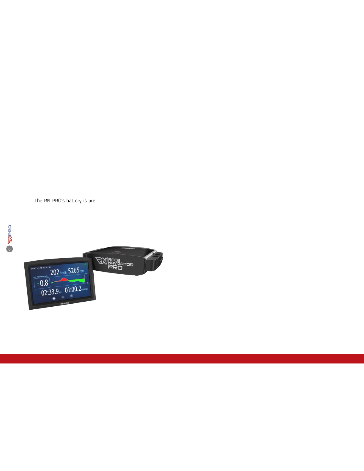
-charged so you can
start using the device immediately.
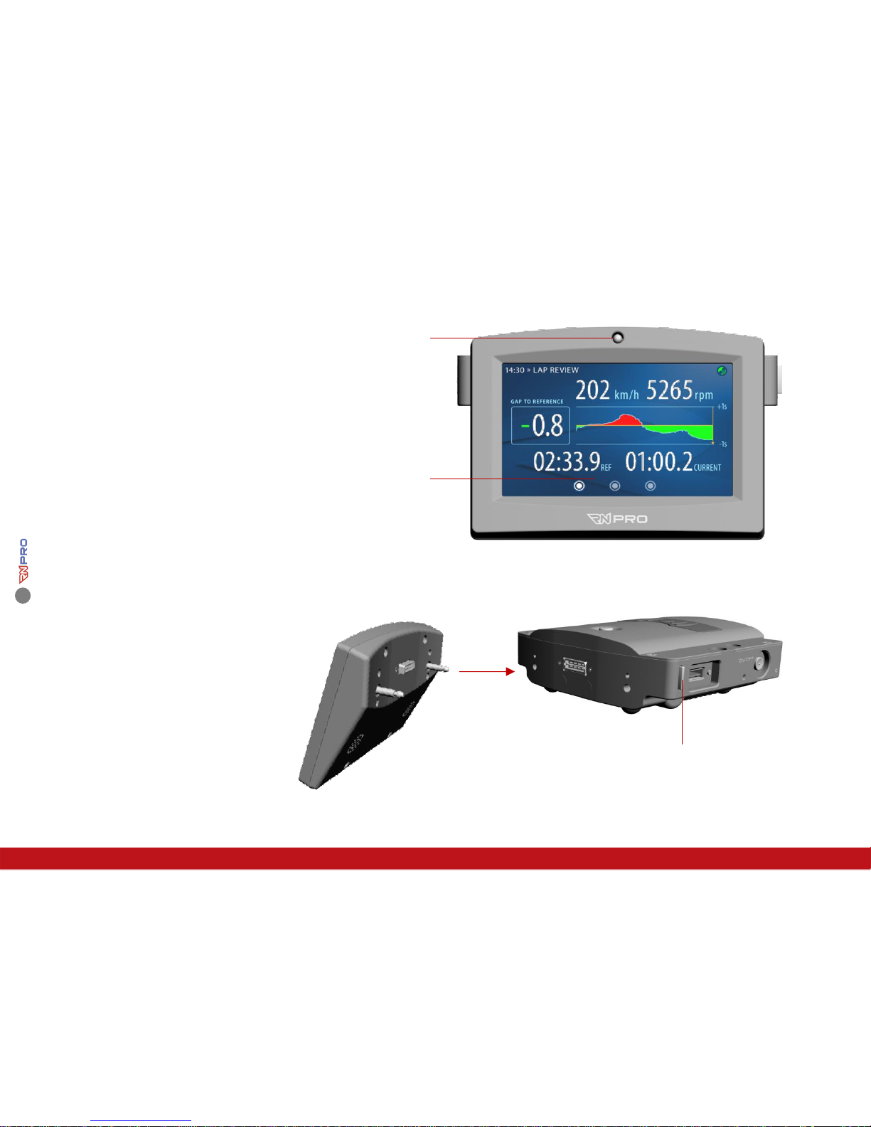
Race Navigator PRO
The RN PRO is an autonomous modularly built system which largely functions
wirelessly. The system is highly flexible and easy to use and sets the standard for
video and data analysis.
A number of functions are available including:
Full HD video recording (1080p/30fps) or HD (720p/30fps),
Cameras withwide-angle lensand image stabilizer,
Night vision camera with HD resolution works up to 0,01 lux,
Composite video and data upto4 cameras simultaneously,
HDMI video output,
High dynamic range microphone,
Recording starts and ends automatically, depending on the
speed,
GPS position and speed(10 Hz),
Acceleration sensor (20 Hz),
Gyro sensor (roll/yaw/pitch) and compass,
Engine speed, throttle position and more car-specific data via
OBD2 or CAN connectors,
Wireless (Wi-Fi) data/videotransfer,
Export of data/videoto USB stick (USB 3.0).