Radcal Dynalyzer IIIU User manual

RAPIDOSE
Rapid Measurements – with a super small footprint detector
USER GUIDE
DYNALYZER
OPERATION MANUAL
Dynalyzer IIIU High Voltage Unit

Warranty for the Model M-96311 Dynalyzer High-Voltage Unit
Radcal Corporation warrants that, in the event that any defects in material or workmanship should
develop within one year of the date of shipment, the company assumes full responsibility for
servicing equipment of its manufacture without charge upon return of the equipment to Radcal,
with shipping costs prepaid by the customer. Costs to return-ship by ground to customers will be
paid by Radcal if the repairs are warranty-applicable.
Radcal shall not be held liable for damages or delays caused by defects beyond making repairs or
furnishing replacement parts, not shall Radcal be liable for any defective material replaced without
Radcal’s consent during the period of this warranty. Radcal reserves the right to perform warranty
services at its own factory.
Non-Warranty Repairs
The calibration of this instrument was correct within specified limits when the instrument left our
factory. Radcal cannot be responsible for injury or damage resulting from improper use or
calibration errors which develop subsequent to our shipment of the instrument.
If Radcal determines that a fault has been caused by misuse, abnormal operating conditions, or
repairs by unauthorized personnel during the warranty period, repairs and shipping costs will be
billed at normal rates.
If the equipment is found to be in proper working condition, Radcal will return-ship the equipment
at customer expense.
Radcal Corporation
426 West Duarte Road
Monrovia, CA 91016-4591 USA
USA (626) 357-7921
Fax USA (626) 357-8863
email sales@radcal.,com
www.radcal.com
Radcal Part # MNL/ST-3672
4078221 Rev:D
Printed: OCT 2017

Dynalyzer – High Voltage Unit OPERATION MANUAL
1
Contents
Preface..................................................................................................................................................................2
Safety Notice.....................................................................................................................................................2
Introduction..........................................................................................................................................................3
General..............................................................................................................................................................3
Basic Principle of Operation..............................................................................................................................3
Anode Current Sensor..................................................................................................................................3
High-Voltage Divider.....................................................................................................................................3
Filament Current ...........................................................................................................................................3
Equipment Supplied..........................................................................................................................................4
Specifications ....................................................................................................................................................4
Installation............................................................................................................................................................8
Inspection..........................................................................................................................................................8
Parts Necessary for Use ...................................................................................................................................8
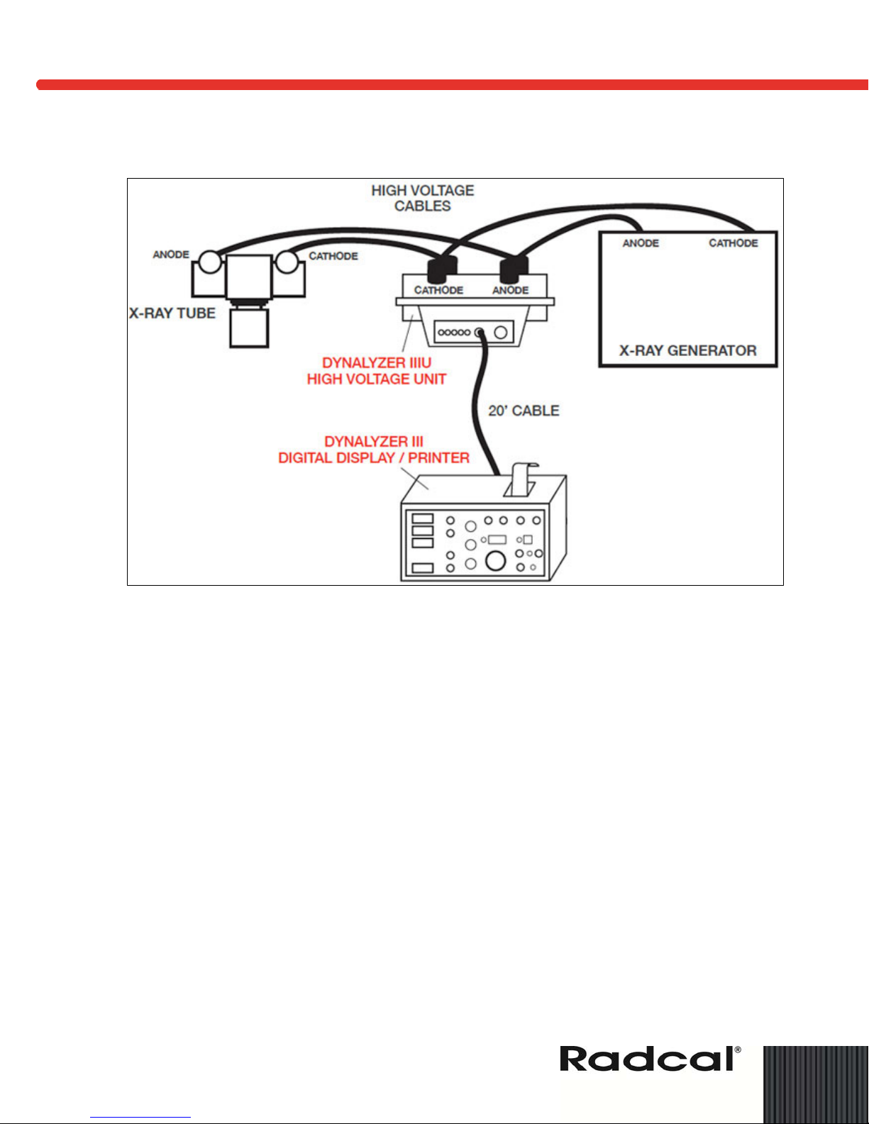
Electrical Connections.......................................................................................................................................9
Precautions...................................................................................................................................................9
High Voltage Cable Connections..................................................................................................................9
Operation............................................................................................................................................................13
Readout Oscilloscope .....................................................................................................................................14
Measurement procedure for kVp and Exposure Time Using Oscilloscope................................................14
Measurement Procedures for mA and mAs using Oscilloscope ................................................................15
Three-Phase Current Measurements (using Oscilloscope)........................................................................15
Fluoroscopic Current Measurements (using Oscilloscope)........................................................................16
Measurements with Digital Display.................................................................................................................16
Current Measurements with Dynalyzer III Digital Display (mA and mAs)...................................................16
Exposure Duration (Time)...........................................................................................................................17
Dynalyzer Digital Display of kVp Measurements........................................................................................17
Filament Current Measurement with the Dynalyzer Digital Display............................................................17
Measurements with Suitable RMS Voltmeter..................................................................................................17
Removing High Voltage Unit from X-ray Installation.......................................................................................18
Interpreting Oscilloscope Measurement Waveforms ......................................................................................18
Single-Phase Current Waveform................................................................................................................18
Three-Phase Current Waveforms...............................................................................................................19
kVp Calibration for X-Ray Generator..........................................................................................................20
Equipment Fault Diagnosis by Voltage Waveform Analysis.......................................................................20
Evaluating Fluoroscopic Current Measurements........................................................................................21
Single-Phase Radiographic Current Measurements using Oscilloscope...................................................22
Filament Current Measurements using Oscilloscope.................................................................................24
How to Select Operating Voltage....................................................................................................................27
Maintenance.......................................................................................................................................................27
System Pressure.............................................................................................................................................28
Failure Modes..................................................................................................................................................28

Dynalyzer – High Voltage Unit OPERATION MANUAL
2
Preface
IMPORTANT: ALWAYS PLUG DYNALYZER, SCOPE, AND
DISPLAY INTO SAME OUTLET.
Safety Notice
This unit is designed to operate at hazardous voltages found in x-ray generators. The operator is
cautioned to observe all safety practices normally associated with x-ray equipment. Among these
precautions are:
1. Never make or break connections in the high voltage circuit when the generator is
energized. In spite of all interlocks present, it is still possible for an accidental firing to
occur.
2. Never assume that a cable voltage is discharged. There is sufficient capacitance in the x-
ray cable to maintain a lethal charge. Touch the pins of any cable to ground to be sure that
there is no residual charge.
3. Inspect cables often. Do not use any cables with a broken braid at the connectors or in the
cable.
4. Always tighten the locking ring of the cable connector to ensure a good ground connection.
Do not overtighten the ring.
5. Use oil or vaporizing compound on all high-voltage connectors to prevent flashover.
6. Keep away from x-ray beam. This system is designed for remote reading so the equipment
should not be placed near the x-ray beam path.
7. Do not knowingly operate this unit in excess of 150 kVp, or in equipment with unstable x-
ray tubes. Severe damage to the equipment may result from an overvoltage condition.
8. Be sure of your grounds. When in doubt, ground tank to transformer.
9. Always monitor tank pressure. Do not use the system if the pressure reads less than 22
psig. Read the maintenance section for refilling or return to the factory.
CAUTION: IMPORTANT HANDLING NOTICE: This unit is a precision high-voltage measurement
instrument and must be handled with as much care as one would handle an
oscilloscope. While it is portable and is designed to sustain normal handling and
transportation shock and vibration, it must not be subjected to excessive shock or
vibration. The precision electronic assemblies contained inside the tank are subject to
damage from abnormal shock transmitted from the heavy flanges on the tank.
Improper handling can cause tank failure and loss of warranty protection.

Dynalyzer – High Voltage Unit OPERATION MANUAL
3
Introduction
General
The Dynalyzer III High Voltage Unit is capable of providing isolated signals analogous to:
1. Anode, Cathode, and Anode + Cathode kilovoltages
2. Anode Current
3. Filament Current (AC)
These signals may be viewed on an oscilloscope, may be measured with a voltmeter, or may be
processed and displayed with the Dynalyzer Digital Display.
This unit has been designed as a calibration instrument and as a diagnostic tool for servicing x-ray
equipment.
This unit is designed for continuous duty, and may be left in the high-voltage circuit indefinitely, if
desired. This feature is desirable in special applications where frequent calibration is required.
This unit is portable. It weighs 32 pounds and is designed to simplify servicing and repair.
Basic Principle of Operation
The Dynalyzer High Voltage Unit is built in two sections. All high-voltage components are located
in a tank pressurized with 30 psig of Sulfur Hexafluoride (SF6) gas. In the base of the unit are
power supplies and buffer amplifiers to adjust the levels of the isolated signals, provide buffering
against cable and instrument loading effects, and provide frequency compensation. In addition,
there is an oscillator which in conjunction with a high-frequency isolation transformer located in the
tank, provides power to operate the anode current sensing system.
Anode Current Sensor
The anode current sensor is an optically-coupled device that is capable of providing an isolated
signal that represents the anode current waveform. The sensor is capable of measuring current in
the range of 1 mA to 2 Amperes with a 2% absolute accuracy ± zero offset. The output conversion
factor is 1 mV/mA for fluoroscopic measurements. The insertion impedance of the unit is 200 ohms
± 5%. The average power rating of this resistor network is 10 watts, and is the only duty cycle
limitation on this unit. The kVp rating is 150.
High-Voltage Divider
The divider consists of two 1000 megaohm sections that are connected between the anode and
ground, and cathode and ground. Each section contains ten (10) 100 megaohm resistors
connected in series. The geometry of the structure provides distributed capacitance that allows a
frequency response of 100 kHz to be obtained by adjustment of the buffer amplifier compensation
capacitor.
Filament Current
Filament current is measured in the common lead of the cathode circuit using an insulated AC
toroidal transformer. The output of the transformer, which is loaded with a 1 ohm resistor, is

Dynalyzer – High Voltage Unit OPERATION MANUAL
4
amplified to a signal level of 0.1 volt (p-p), and is frequency compensated to a maximum frequency
of 20 kHz.
Equipment Supplied
As supplied, the High Voltage Unit is shipped with the following components:
•High Voltage Unit Assembly
•12 ft. Coaxial Cable, BNC Connectors each end (2 each)
•Vaporproofing Compound (2 [two] 1.5 oz. tubes)
•Line cord (6 ft.)
•Dummy plugs (2)
Additional equipment required for use includes:
•Dual-trace oscilloscope to display mA and kV waveforms
Optionally, a digital voltmeter (DVM) or the Dynalyzer III Digital Display
•Two (2) 3-conductor, 5-foot long high-voltage x-ray cables, Federal Standard Connector
Specifications
Calibration Standard Factory calibrated, all output parameters traceable to National
Bureau of Standards
Electrical Rating (maximum
peak voltages) Anode to cathode: 150 kVp
Anode to ground: 85 kVp
Cathode to ground: 85 kVp
Current from x-ray to
Generator (max) Anode (peak): 2 amps for 8 msec
Anode (continuous): 100 mA
Filament: 10 amps (ac rms)
D.C. Voltage Division Ration 10,000: 1 ± 1% (10kV to 75 kV plus & minus polarity)
Voltage Divider Load 1000 megohms to ground
2000 megohms anode-cathode
Duty Cycle Continuous
Frequency Response Voltage: 0-1 kHz ± 2.9%
1 kHz – 100 kHz ± 12.2%
Anode current: 0-5 kHz ± 1db, ± 2% to 300 Hz (Rad. Range)
0-500 Hz ± 1 db, ± 2% to 100 Hz (Fluoro. Range)
Filament current: 20 Hz to 20 kHz, ± 1db
Filament Current Sensor Output level: 0.1 volt (p-p) per ampere (p-p)
Ratio: 0.1 volt/ampere (±5% + zero offset)
Noise level: 0.1 ampere, rms
Anode Current Sensor Current rating: 1 mA to 2 amps
Insertion impedance: 200 ohms ±5%
Power rating: 10 watts

Dynalyzer – High Voltage Unit OPERATION MANUAL
5
Ratio: 1 millivolt/milliampere, (Rad. Range) 20
millivolts/milliampere (fluoro Range)
Accuracy: 1 mA to 10 mA, ± 2% (± zero offset; Fluoro range)
10 mA to 2 Amp, ± 2% (± zero offset; Rad Range)
Noise level: 2 mV (p-p) (Max)
Gas Volume 0.5 cubic foot
Pressure Gauge 0-30 psig scale
Insulation Sulfur Hexafluoride gas (SF6) @ 25-30 psig
Gas Relief Valve 22 psig
Gas Filling Valve Schrader type, spring loaded
Test Level Connectors Scope inputs: 5-BNC type, insulated
Digital display: 1-Bendix PT 02A-16-8P
High Voltage Receptacles
3-conductor cables Receptacles conform to NEMA XR-7-1979
Coaxial Cable Two 12-foot long cables RG-58/U with BNC connectors
Temperature Operating: +15° to +30°C
Storage: - 10° to + 50°C
Dimensions See Outline Data
Weight 32 lbs (14 kg)
Power Requirements 104-125 or 208-240 VAC
50-60 Hz, 50 watts
Fuse 0.25 amp for 120 VAC, or 0.25 amp for 240 VAC

Dynalyzer – High Voltage Unit OPERATION MANUAL
6
Figure 1: Cabling Data

Dynalyzer – High Voltage Unit OPERATION MANUAL
7
Figure 2: Outline Data (dimensions in inches)
Calibration
R
Date
Report #
Radcal Corporation
By
Due
S/N
monrovia,CA 91016
(818)357-7921 FAX(818)357-8863
DYNALYZER U
RDIVIDERVOLTAGEHIGH
FIL
Radcal Corporation
R
kV mA
9.00
13°
26°
12.97
0.37
8.13
3.21
1.26
0.63
24.75
22.88
5.19 5.19
3.21

Dynalyzer – High Voltage Unit OPERATION MANUAL
8
Installation
Inspection
Inspect the unit after receipt for signs of physical damage. Report any damage to the carrier at
once if any occurred in shipping.
Observe that tank pressure is within the 15-30 psi range. If the pressure is below 10 psi, the unit
should be recharged. Refer to the Maintenance section.
Verification of the operation of the unit may be made with the aid of a digital voltmeter (DVM). Plug
the line cord into the 115 VAC, 60 Hz power source. Measure the output voltages from the BNC
output connectors. All voltages should be within ± 1 millivolt with respect to ground. Operation may
be verified by actual operation or by preliminary low-voltage calibration techniques.
Reasonable care should be taken in the handling of this unit as undue shock may loosen the
integrated circuits from their sockets or upset the optical system in the current detection unit.
The equipment setup depends on the tests to be performed and the auxiliary equipment used.
Details are contained in subsequent paragraphs.
This section describes the proper techniques for the installation of the High Voltage Unit for
calibrating or diagnostic investigation of an x-ray installation. The user is again cautioned about
possible safety hazards due to the presence of high voltage x-ray radiation, and is requested to
review the safety notice in the Preface.
Parts Necessary for Use
Two 12-foot long RG-58U cables with BNC connectors at each end for oscilloscope connections.
(Supplied)
Besides the High Voltage Unit, the following parts are required:
•Two high-voltage cables, approximately 5 feet long with ASA (Federal) terminals at each
end
•Two ASA (Federal) dummy high-voltage receptacle plugs (Supplied)
•Two 1.5 oz. tubes of vaporproofing compound for cables and plugs (Supplied)
•Small quantity of alcohol for cleaning high-voltage cable receptacles and terminals
•A piece of lead sheet 0.5 in. thick for blocking x-ray tube port, if no collimator is present
•A digital voltmeter
A differential input scope is not necessary as a composite A + C output is provided. Dual-trace or
dual-beam capability is desirable to allow mA and kV to be viewed simultaneously.
NOTE: If the oscilloscope does not have a storage feature, an oscilloscope camera will be
useful to permit analysis of the waveform after the trace fades.
•A BNC for binding post adapter (if needed)

Dynalyzer – High Voltage Unit OPERATION MANUAL
9
Electrical Connections
The electrical interconnections are dependent on the test equipment used and the tests that will be
performed. The High Voltage Unit can be used with an oscilloscope, digital voltmeter of the
Dynalyzer II or III Digital Display. These instructions will be directed primarily for use with an
oscilloscope readout. The Digital Display unit operation is described in a separate document.
Precautions
X-ray equipment is operated at lethal voltages. The operator must make certain that the
main power switch is off when making or breaking connections in the high-tension circuit
and that the cables are discharged before touching any high-tension lines.
Damage to the high voltage unit, the transformer, and the x-ray tube can occur if the cable
plugs are not properly handled. Cable plugs are usually treated with silicone oil,
transformer oil, or a vaporproofing compound. This lubrication prevents corona or arcing
from occurring in the receptacle. Oil is often used in vertically mounted receptacles while
vaporproofing compound is used in conditions where the oil could seep out, such as in the
horizontal plans when cables are installed upside down. If the cables in an installation
have some vaporproofing compound on them, it would be in the best interest of system
compatibility for the operator to insulate the cables from the Dynalyzer in a similar manner.
If oil is used, and appears in to a depth of 1/8 in. in the receptacle, then additional oil is not
necessary. Otherwise, add oil as necessary.
High Voltage Cable Connections
The Dynalyzer III High Voltage Unit can be connected into the high voltage circuit in several ways.
Each configuration implements the best method of measurement for the particular selected
application. The following paragraphs outline these methods.
Series Connection (Figure 3)
This method is most often used since all x-ray exposure parameters attainable with the
High Voltage Unit are measured e.g., Anode kVp, Cathode kVp, Anode + Cathode kVp,
mA and filament current. The High Voltage Unit should be connected as close to the x-ray
tube as possible (5-foot cables recommended) in order to properly observe the possible
effects of cable charging during exposures of less than 100 mA. The High Voltage Unit
may be located at the transformer when it is physically impossible to locate it close to the
x-ray tube, bearing in mind the effects of cable charging.
Series Connection Anode Only (Figures 3 and 4)
The addition of a short high voltage cable necessary to complete the cathode circuit
between the High Voltage Unit and the x-ray tube may have an adverse effect in certain
situations, predominantly due to contact resistance. The added impedance of this cable
and connections in the filament circuit may have a loading affect on the filament
transformer. Therefore, when the Dynalyzer and short high-voltage cable is removed from
the circuit, the filament current may increase resulting in an increase in mA which will in
turn load the high tension transformer resulting in a lower kVp. The percent error will vary
as a function of the loading characteristics of the filament transformer and high tension
transformer as well as the total length of the high-voltage cables already in the circuit.
Because of this phenomenon, the following procedure is recommended:

Dynalyzer – High Voltage Unit OPERATION MANUAL
10
1. Use the shortest high-voltage cable jumper as physically possible between the High
Voltage Unit and the x-ray tube (recommended length 5 feet).
2. Insert both the anode and cathode sections of the High Voltage Unit in the x-ray circuit.
(See Figure 3).
3. For each desired measurement, record the anode kVp required to obtain the anode to
cathode kVp at the mA of interest.
4. Remove the cathode side of the High Voltage Unit from the circuit, leaving the anode side
connected, and complete the circuit from the high tension transformer to the x-ray tube.
(See Figure 4).
5. Readjust the kVp and mA to precise values using the anode kVp readings and mA
readings. This eliminates the effect of the added cathode cable insertion.
The setup as shown in Figure 4 may also be employed in grid-pulsed applications to accurately
determine anode kVp and x-ray tube current. This technique does not measure cathode kVp or
filament current because the cathode side of the Dynalyzer is not connected.
Series Parallel Connection
This method can only be used with x-ray generators having auxiliary high-voltage
receptacles capable of simultaneous activation.
This setup shown in Figure 7 enables the measurement of all parameters except filament
current and eliminates the possible adverse effect of an additional test cable in the filament
circuit.
NOTE: The Dynalyzer III has been designed for remote reading to minimize x-ray danger to
the operator.
CAUTION: The High Voltage Unit, Digital Display and oscilloscope must be connected to
the same grounded outlet or damage may result to the equipment and/or the
accuracy of the readings may be affected.

Dynalyzer – High Voltage Unit OPERATION MANUAL
11
Figure 3: Series Connection
ANODE
X-RAY
TUBE
CATH
TUBE
CATH CATH
TRANS
ANODE ANODE
TRANSTUBE
VOLTAGE
HIGH
UNIT
ANODE
TRANSFORMER
CATHODE
CABLES
VOLTAGE
5 FT HIGH EXISTING
CABLES
Figure 4: Series Connection Anode Only
ANODE
X-RAY
TUBE
CATH
TUBE
CATH CATH
TRANS
ANODE ANODE
TRANSTUBE
VOLTAGE
HIGH
UNIT
ANODE
TRANSFORMER
CATHODE
5 FT HIGH
VOLTAGE
CABLES CABLES
EXISTING

Dynalyzer – High Voltage Unit OPERATION MANUAL
12
Figure 5: Mammography Machine Connection
X-RAY
TUBE
CATH
TUBE
CATH CATH
TRANS
ANODE ANODE
TRANSTUBE
VOLTAGE
HIGH
UNIT TRANSFORMER
CATHODE
CA-4 4-PIN HV CABLES
Figure 6: Mammography Machine Connection GR DMR Only
X-RAY
TUBE
PLUG
CATH
TRANS
DUMMY
ANODE
TUBE
ANODE
TRANSFORMER
HIGH
VOLTAGE
UNIT
TRANS
CATH
ANODE
HV TEST
POINT
PMI H44 ADAPTER CABLE
(LORAD OR HOLOGIC)
OR PMI H0493-005
TUBE
ANODE

Dynalyzer – High Voltage Unit OPERATION MANUAL
13

Dynalyzer – High Voltage Unit OPERATION MANUAL
14
Operation
This unit is designed to operate with three possible read-out devices:
1. A suitable oscilloscope
2. The Dynalyzer II or III Digital Display
3. A digital voltmeter
All measurements can be made with the optional Digital Display Unit and most measurements can
be made with the oscilloscope (requiring interpretation contained in the Measurements with
Suitable RMS Voltmeter section of this manual). In addition, some measurements can be made
with a voltmeter readout.
CAUTION: As 5 foot long high voltage cables are normally used to connect the Dynalyzer III High
Voltage Unit to the x-ray tube (necessitating that the HVU be placed on the table) the
possibility exists that the HVU may be inadvertently left in the primary beam. If this
occurs, the SF6gas used to insulate the internal components in the tank section of the
HVU may become sufficiently ionized to cause gross measurement errors, e.g., 20 to
30 kV. In order to guard against this possibility, the user must be careful to angle the
tube away from the HVU or close the collimator shutters.
Readout Oscilloscope
a. Measurement of kVp and exposure duration for both single-phase and three-phase machines
may be read directly from the oscilloscope trace.
b. Current measurements for radiographic exposures may be read from the oscilloscope trace.
Measurement procedure for kVp and Exposure Time Using Oscilloscope
a. Connect the oscilloscope to the High Voltage Unit as shown in Figure 7.
b. Adjust the gain of the preamp of the oscilloscope for 2-volts per division.
c. Adjust the horizontal time base for 10 milliseconds per division.
d. Connect the scope to the Anode + Cathode output or to the separate outputs if switching
between individual and summed outputs is desired. The exact switching will vary due to
differences in x-ray high-voltage generator controllers. Refer to specific instructions for the
model being calibrated.
Anode + Cathode Output
It is often necessary to view kVp and mA on the same dual trace oscilloscope. As this unit
features a composite kV output with a separate BNC connector, the Anode + Cathode kV

Dynalyzer – High Voltage Unit OPERATION MANUAL
15
waveform may be viewed on a conventional scope. The scale factor is 0.5 V/10 kVp
(20000:1 ratio). The reduced scale factor is needed to prevent saturation of the amplifier.
The individual outputs are provided to allow checking transformer balance, or for use
where multi-channel plug-in scopes are available for viewing all available data, or where
the operator wishes to switch between dual trace and the add/invert mode (allowing the
summation to occur at the scope).
Figure 7: Series Connection with Oscilloscope or Digital Voltmeter
Measurement Procedures for mA and mAs using Oscilloscope
This unit provides a unique means for viewing and measuring the current waveform in an x-ray
generator. Interpretation may require some analysis on the part of the user. In general it will be
found that three-pulse (constant potential) current measurements can be easily obtained from the
oscilloscope trace while single-phase measurements will require some calculation.
A storage oscilloscope, or oscilloscope camera will significantly aid in analyzing single-phase
measurements.
Three-Phase Current Measurements (using Oscilloscope)
Current measurements in three-phase equipment may be read directly from the oscilloscope trace.
Figure 8 shows a typical three-phase current waveform. By visual inspection, the average value
may be read from the oscilloscope trace. The scale factor is 1 millivolt per milliampere. Through
practice, the average area of ripple above and below the estimated current value should be equal.
The x-ray tube is an emission limited device. Normally, the peaks of the current waveform have a
lower slope than the voltage waveform and therefore the ripple in the current will be smaller than
the ripple in the three-phase voltage.
-
+
OR
OSCILLOSCOPE
DIGITAL VOLTMETER
+
X-RAY
TUBE
-
TUBE
CATH GEN
GEN
ANODE ANODE
TUBE
ANODE
TRANSFORMER
CATHODE
CABLES
VOLTAGE
5 FT HIGH
CABLES
EXISTING
CABLES
RG-58U

Dynalyzer – High Voltage Unit OPERATION MANUAL
16
Figure 8: Typical Three-Phase Current Waveform
Fluoroscopic Current Measurements (using Oscilloscope)
For these measurements, the front panel switch should be set to the FLUORO position. Three-
phase fluoroscopic current measurements can be evaluated per the Three-Phase Current
Measurements section above. Single-phase fluoroscopic measurements may fall into two
categories: 1) filtered and 2) unfiltered. At low current levels (below 5 mA) in systems with
sufficient cable, or external capacitor banks, the voltage applied to the x-ray tube may appear to be
purely direct current. The current waveform will depend on the location of the Dynalyzer High
Voltage Unit with respect to the x-ray tube. Use the FLUORO position if there is significant low
level noise filtering by the amplifier circuitry in the High Voltage Unit.
Measurements with Digital Display
The Dynalyzer II or III Digital Display can be used in conjunction with the high voltage unit to
provide the following five measurements simultaneously:
1. mA and mAs
2. Exposure time (triggered by kV, mA, external trigger or internal (line) trigger
3. kVp of anode or cathode only or both
4. Auxiliary readout of filament current or line voltage
An oscilloscope can be connected in conjunction with the Digital Display to obtain a visual image of
the waveform measured. Refer to the Digital Display Instructions for additional information.
Current Measurements with Dynalyzer III Digital Display (mA and mAs)
The Dynalyzer III Digital Display contains all necessary signal processing required for accurate
measurements of either mA or mAs in all modes described above. In operation, the incoming

Dynalyzer – High Voltage Unit OPERATION MANUAL
17
analog signal is digitized, and the resulting pulses are stored. Thus, the pulse count gives a true
indication of the mAs of an exposure. Simultaneously with the current integration, the exposure
time is being counted by a digital clock. The average current is displayed by electronically dividing
the mAs by time.
Triggering for this measurement may be made with current, voltage, external trigger, or manually
(auto mode).
Exposure Duration (Time)
The third line of the display is the exposure time that is triggered by the kV, mA, auto (internal), or
an external signal.
Dynalyzer Digital Display of kVp Measurements
The Dynalyzer Digital Display is interconnected to the High Voltage Unit with a 20-foot long
shielded cable. The Digital Display is powered from the 120/240 VAC, 50/60 Hz line.
kVp measurements are made by selecting either the sum of Anode + Cathode or the individual
terminals with respect to ground. The Digital Display is triggered by dialing in the fraction of the
peak or preset (absolute) amount of kVp or mA that is considered the beginning of the exposure,
i.e., 0-10% for single-phase and 75% for three-phase operation. A test exposure is made to set the
gain factor of the display. Each subsequent exposure will trigger both the peak detector circuit and
the electronic time clock. Both kVp and time in milliseconds will be displayed. (Current and filament
will also be displayed.) A delay, adjustable up to 20 milliseconds, is provided to prevent
measurement of the leading edge which may contain substantial overshoot of a three-phase
exposure.
In both single and three-phase exposures, the kVp displayed will be the highest value within the
exposure, with the exception of the kVp present during the delayed period.
Details on operation are supplied in the Digital Display Instruction Manual supplied with the Display
Unit.
Filament Current Measurement with the Dynalyzer Digital Display
Pressing MANUAL TRIGGER after selecting AUTO at the TRIGGER SOURCE switch on the
display causes the filament current to be displayed at an update rate of 0.5 second.
Measurements with Suitable RMS Voltmeter
An ac rms voltmeter, such as the Data Technology Model 31 may be used to obtain a readout of
the filament current.
Rms conversion modules are available from Analog Devices, Burr-Brown, and Intronics, as well as
other manufacturers. These modules require ± 15 VDC power to operate and a digital voltmeter to
display their output.

Dynalyzer – High Voltage Unit OPERATION MANUAL
18
Removing High Voltage Unit from X-ray Installation
CAUTION: Turn off the main power before removing the Dynalyzer. At the completion of testing
remove the cables in the sequence provided to prevent any possible cross connection
of anode and cathode cables.
1. Remove anode cable first. The jumper cable from the Dynalyzer to either the x-ray tube or
high-voltage transformer, depending on test configuration, should be disconnected. Do not
handle the insulator.
2. Touch the pins of the cable to ground to remove any residual charge remaining in the cable.
NOTE: Grid bias operation often causes large residual cable voltages if no bleeder resistance
is present at the high tension transformer.
3. Clean off the oil or grease and place a protective cover over the cable ends.
4. Disconnect the system cable from the other anode connector of the Dynalyzer.
5. Reconnect the x-ray tube to the high-voltage transformer. Be sure sufficient oil or
vaporproofing compound remains in the receptacle or on the cable.
6. Repeat the procedure for the cathode cables.
Interpreting Oscilloscope Measurement Waveforms
Three-phase current waveforms are generally easier to interpret than single-phase waveforms,
however, following the procedure outlined, measurements may be made for both waveforms.
Fluoroscopic exposure current values may be read directly on the DVM. The scale factor is 20
mV/mA. Filament current may be viewed on the scope, or may be measured with a digital
voltmeter connected to the High Voltage Unit readout terminal. The waveform of the filament
current will to some extent influence the accuracy of the reading of the peak reading as ac rectifier
circuit used in most DVMs. For low current level exposures, the zeroing of the High Voltage Unit
should be checked and adjusted, if necessary, through the access hole on the base. Fluoro gain
should be selected. The limiting parameter for measurements will be the response time of the
DVM. In general, exposures having a duration of at least 3 seconds should be adequate for most
DVMs to integrate and display.
Single-Phase Current Waveform
Figure 9 illustrates the waveform of a typical single-phase generator for an exposure of 200 mA,
120 kVp, 1/20 sec. A properly timed single-phase generator will contain one or more complete
pulses, each lasting 1/120 of a second on a 60 Hz power line, or 1/100 of a second on a 50 Hz
system. Thus, a single-phase exposure time for normally operating equipment is N x 1/120, where
N is the number of pulses. For longer exposures, the time may be read from the start of the first
major pulse to the end of the last pulse. The trailing off of the voltage, (region C of Figure 9), is due
to cable capacitance. Cable capacitance is also responsible for the failure of the voltage to drop to
zero at the end of each pulse.
In low-level fluoroscopic systems, or in systems with a capacitor bank, level B may be equal to the
kVp. By convention, kVp is the greatest amplitude value observed, which may vary by amount D.
Pulse A is due to the system of contacting which provides for the closing of the contactor during
the end of the last pulse preceding the beginning of the exposure. This is done to minimize the
Table of contents
Other Radcal Control Unit manuals
Popular Control Unit manuals by other brands

schmersal
schmersal AES 1337 operating instructions

Siemens
Siemens MVS661 N Series Mounting instructions

PDi
PDi PD295-001 Installation and operating instructions

Texas Instruments
Texas Instruments TRF7970A BoosterPack user guide

Pentair
Pentair FLECK3150 DOWNFLOW Service manual

Econ
Econ 7755 Installation & operation manual