SERIES AJ
4
EXPLANATION & USE OF
RATINGS & SERVICE FACTORS
Mechanical ratings and service factor FM
hour of operation.
used instead of Fm.
refer to application engineering.
application engineering.
Thermal ratings and service factors
Double Reduction Units
General
250
500
875
1160
1450
1750
2400
3500
280-610
730
860
280-610
730
860
280-610
730
860
280-610
730
860
280-610
730
860
280-610
730
860
280-610
730
860
280-610
730
860
1.0
1.0
1.0
1.0
1.0
1.0
1.0
1.0
1.0
1.0
1.0
1.0
1.0
1.0
1.0
1.0
1.0
1.0
1.0
1.0
1.0
1.0
1.0
1.0
1.46
1.44
1.46
1.46
1.38
1.46
1.46
1.34
1.41
1.46
1.30
1.37
1.46
1.28
1.34
1.46
1.26
1.32
1.46
1.22
1.30
1.46
1.13
1.24
1.72
1.52
1.72
1.72
1.56
1.72
1.72
1.47
1.60
1.72
1.43
1.54
1.72
1.39
1.50
1.72
1.36
1.46
1.72
1.30
1.42
1.72
1.23
1.34
1.96
1.92
1.96
1.96
1.75
1.96
1.96
1.64
1.79
1.96
1.56
1.72
1.96
1.52
1.66
1.96
1.47
1.61
1.96
1.39
1.55
1.96
1.30
1.45
2.32
2.26
2.32
2.32
2.02
2.32
2.32
1.84
2.07
2.32
1.75
1.96
2.32
1.69
1.88
2.32
1.63
1.81
2.32
1.53
1.75
2.32
1.41
1.61
2.86
2.75
2.86
2.86
2.38
2.86
2.86
2.16
2.45
2.86
2.05
2.32
2.86
1.97
2.21
2.86
1.89
2.14
2.86
1.75
2.03
2.86
1.58
1.85
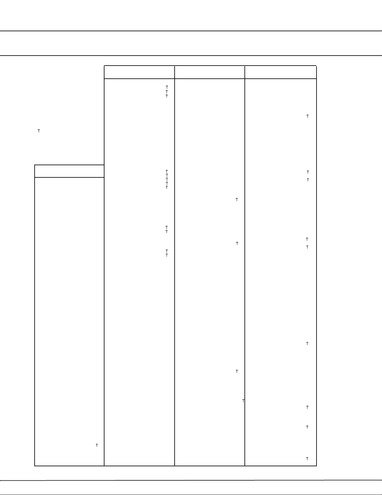
Input
shaft
speed
Unit
>60 >50-60 >40-50 >30-40 >20-30 >20
% Running time per hour
Table 4. Thermal service factor Fd
0 to 100
>100 to 200
>200 to 300
>300 to 400
>400 to 500
>500 to 600
>600 to 700
>700
Output
Speed
1.0
1.0
1.0
1.0
1.0
1.0
1.0
1.0
1.0
1.0
1.0
1.0
1.0
1.0
1.0
1.0
DEF
1.0
1.0
1.0
1.0
1.0
1.0
1.0
1.0
KMN
Refer to
Engineering
PST
Mounting Position (See pages 9 and 10)
Table 3. Thermal service factor Fp (Single Reduction units)
temperature oF
Factor Ft
-20 020 40 60 68 80 100 120
1.64 1.50 1.36 1.22 1.07 1.00 0.92 0.77 0.63
Table 2. Thermal service factor Ft
Prime mover
or
internal
engine
internal
engine
Duration of
service hrs
Under 3
3 to 10
Over 10
Under 3
3 to 10
Over 10
Under 3
3 to 10
Over 10
Table 1. Mechanical service factor Fm
0.80
1.00
1.25
1.00
1.25
1.50
1.25
1.50
1.75
Uniform
0.80
1.00
1.25
1.00
1.25
1.50
1.25
1.50
1.75
Moderate
Shock
0.80
1.00
1.25
1.00
1.25
1.50
1.25
1.50
1.75
Shock