Radio Corporation Of America 100 Operating and maintenance manual

RCA LOUDSPEAKER
MODEL 10 0
Reg. U. S. Pat. Office
SERVICE NOTES
NS-100-2
Second Edition-November, 1926
RADIO CORPORATION OF AMERICA
326 Broadway
New York City
Prepared by
NATIONAL SERVICE DIVISION
233 Broadway, New York City
DISTRICT SERVICE STATIONS
10 South La Salle Street
Chicago, Ill.
3308 Fourteenth Street, N. W.
Washington. D. C.
28 Geary Street
San Francisco, Cal.
www.americanradiohistory.com

A Word or Two About Service
Service goes hand in hand with sales. The well informed Radiola Dealer renders service at
time of sale in affording information as to proper installation and upkeep. Subsequent service
and repair may be required by reason of wear and tear and mishandling, to the end that Radiola
owners may be entirely satisfied.
Obviously this service can best be rendered at point of contact and therefore, Dealers and
Distributors, who are properly equipped with a knowledge of the design and operation of
Radiolas, occupy a favorable position to contract for this work.
To assist in promoting this phase of the Dealers' business the National Service Division
of the RCA has prepared a series eef Service Notes-of which this booklet is a part-containing
technical information and practical helps in servicing Radiolas.
This information has been compiled from experience with Radiola Dealers' service prob-
lems, and presents the best practice in dealing with them. A careful reading of these Service
Notes will establish their value to Dealer and Distributor, and it is suggested they be preserved
for ready reference.
In addition to supplying the Service Notes the RCA, through its Service Stations, has
available to Dealer and Distributor the services of engineers who are qualified to render valu-
able help in solving service problems.
Property of Radio Corporation of America. Confidential and to be used only by its
authorized distributors and dealers in furnishing service in connection with its apparatus.
Copyright 1926-Radio Corporation of America
www.americanradiohistory.com

RCA Loudspeaker Model 100 Service Notes
Non.-Cone assembly of RCA Loudspeaker Model 102 is
identical to Model .100 less the filter unit
Prepared by
NATIONAL SERVICE DIVISION
Instructions NS-100.2
PART I
RCA Loudspeaker Model 100 is of the free floating cone type. It is suspended at
the outer edge'by means of a strip of soft kid which holds the cone in a central position
but does not impede its movement to any great degree. The cone is attached rigidly to
the speaker mechanism at the center.
In servicing Model 100 Loudspeaker always make certain that the output of the
Radio Receiver used in conjunction with it, is of good quality. If distortion is present in
the Radio Receiver, RCA Model 100 Loudspeaker will reproduce that distortion as
faithfully as it does the tone variations of the program.
Rattling sounds, or the so-called "paper rattles," are generally caused by a distor-
tion in the lower tone registers of the amplifying system of the Radio Receiver. It is
therefore quite important to first check the Receiver for quality of signal. This may
be done by substituting another loudspeaker of known quality or else by replacing the
loudspeaker with a pair of headphones. If distortion is present either in the second
loudspeaker or the headphones it is a positive indication that the trouble is originat-
ing in the Radio Receiver.
Similarly, if the Radiotrons in the Receiver are overloaded by an abnormally strong
signal being forced through the amplifiers, distortion will follow.
If it is definitely established, however, that the distortion or rattle complained of is
not due to a defect or improper adjustment of the Radio Receiver, but is apparently
caused by the Loudspeaker itself, it may be the result of one of the following conditions:
(A) Foreign material interfering with armature vibration.
(B) Armature striking the pole piece.
(C) Cone misaligned.
(D) Excessive pressure on the stylus.
(E) Bent stylus.
(F) Loose or bent connecting rod.
Figure 1 shows a rough sketch of the complete armature assembly and its relation
to the cone. The armature vibrates between the pole pieces (not shown), this motion
being transmitted through the stylus to the thrust lever. The thrust lever is held rigidly
to one of the motor side pieces. It is attached rigidly to the cone by the connecting rod.
Dirt at any of these points may cause distortion.
On inspecting the RCA Model 100 Loudspeaker, note whether or not the stylus is
bent, if so straighten it. The cone is attached to the connecting rod by means of a small
nut "B", Figure 1. The end of the connecting rod is threaded. Make certain that the
cone is drawn up tight to the connecting rod.
If the two foregoing points have been checked and found to be O.K., note whether or
not the armature is striking the pole pieces. Figure la and Figure 2 show the relation
of the armature to the pole pieces. There should be a space approximately .010 inch
Between the armature and the pole pieces, Figure la. This is true at both ends of the
armature. 3
www.americanradiohistory.com

Fig. 1-Moving part of motor
Fig. la-End view of motor
Method of adjusting armature clearance
www.americanradiohistory.com

If either end of the armature strikes the pole piece a very disagreeable rattle will
result. To correct a misalignment of the armature a pair of spacer tools, shown in
Figure 3, and a screwdriver will be necessary. These spacer tools should be made
of .010 phosphor bronze stock aborit 1/8 inch wide. The distance between the open
ends of the tool should he .091 inches. See Figure 3a.
Any loose screws, nuts or parts in the speaker may cause rattles and for that reason
in making adjustments all screws should be seated properly, which means that all screws
and nuts should be drawn up firmly enough to prevent their loosening when the speaker is
placed in operation. Care should be taken to prevent stripping of the threads on the
screws and nuts as well as to prevent torsion of the elements held in place by such
screws and nuts.
To readjust the armature it will be first necessary to free it. Figures 4 and 5 show
the method of doing this. The screws shown as "C" should be backed off about two
turns. Do not remove them entirely.
When the two screws are loosened it is a simple matter to insert one of the spacer
tools between each of the two armature ends and the pole pieces as shown in Figures 6
and 7.When the spacing tools are inserted the clearance between the armature and the
pole pieces must necessarily be the required ten thousandths as this is the thickness
of the blades of the two spacers.
After the spacer tools have been inserted, one at each end, the two screws "C" that
were loosened (Figures 4 and 5) should be tightened firmly. Figure 8 shows the method
of tightening the upper screw with the spacers in place.
After the two screws have been tightened the spacer tools should be removed
and the Loudspeaker tested. If the rattle has been eliminated no further adjustment will
be necessary. If, however, the rattle is still present it may be due to the fact that the cone
is out of centre with respect to the connecting rod.
To correct this, again refer to Figure 2. The screw "d" holds the thrust lever.
When this screw is loosened the cone will automatically assume the proper position and
the screw "d" should then be tightened down. Care should be taken that the sides of the
thrust lever, visible in Figure 2, be held at right angles to the pole pieces as shown when
tightening "d".
The Loudspeaker should again be tested. If the rattle still persists it is probably due
to an excessive pressure on the connecting rod which may be corrected as shown in Figure
9. A soldering iron should be applied to the point where the inner end of the stylus is
soldered to the thrust lever. The solder at that point should be softened sufficiently to
allow free movement of the stylus. Here again the adjustment is automatic and it is only
necessary to keep the solder soft until this readjustment takes place.
PART II
Should it become necessary to replace the field coils due to burn-out or other causes,
it will be necessary to remove the entire reproducer unit.
The procedure is as follows:
1. Remove the flexible leads of the coils from the binding posts. Tag the leads
as they are removed so that when the unit is reassembled they may be connected to the
proper binding posts. THIS IS IMPORTANT.
2. Remove the small nut holding the cone to the connecting rod shown in Figure 1.
5
www.americanradiohistory.com

3. Remove the nuts F, Figure 10, from the upper supporting screws "H". A
small open end wrench will be necessary for this operation as it is necessary to remove
these nuts by inserting the wrench between the cone and the frame.
4. Unscrew the lower supporting screw G, Figure 9, and remove the strap "N".
5. Remove the unit by pulling out. Do not strain the cone or the connecting rod
when removing the unit. Make certain that the connecting rod slides out freely as the
unit is removed.
6. Remove the two screws "H", Figure 10, holding the motor in place. These
screws thread into the spacer bushings "E".
7. Place a piece of iron on the ends of the horseshoe magnet and slide the motor
off. The piece of iron takes the place of the motor and acts as a keeper on the magnet.
8. Remove the screw holding the thrust lever to the motor frame "D", Figure 2.
9. Unsolder the thrust lever from the stylus and remove Point "E", Figure 1.
10. Remove the two armature screws "C", Figures 4 and 5.
11. Dissemble the motor by removing the two countersunk screws. One of these
screws "K" is shown in Figure 2. The coils are then accessible, but the armature is still
in position in the center of the coils. Figure 11.
Fig. 3-Spacer tools
.091.
.010 0.125« {-
Fig. 3a-Spacer tool dimensions
Freeing the armature
6
www.americanradiohistory.com

12. Slip one coil over the free end of the armature and then slip the second coil
off the armature and stylus. All parts before re-assembling should be thoroughly
cleaned and freed from all traces of dust or dirt and metal filings, etc. Use a brush to
remove foreign matter from the parts. Avoid the use of liquid cleaners as they often
induce corrosion.
The re-assembly should be a reversal of the operation just described.
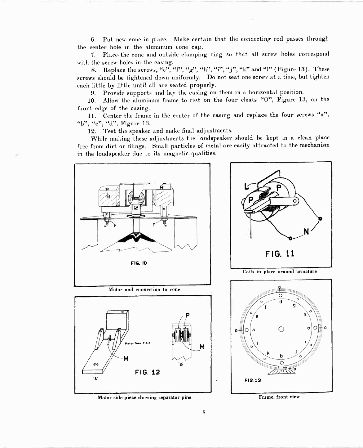
1. Place the coils "P"-"P", Figure 11, in proper position around the armature.
The small length of wire connecting the two coils in series should be at the outside of
each coil when assembled, "L", Figure 11.
2. Place the coils with armature in position onone of the motor side pieces, Figure
12. Place the other motor side pieces in place and screw the assembly together by means
of the screw. In making this assembly make certain that the small pins "M", Figure 12,
projecting from the inner side of the motor side piece, separate the two field coils as shown
in "B", Figure 12.
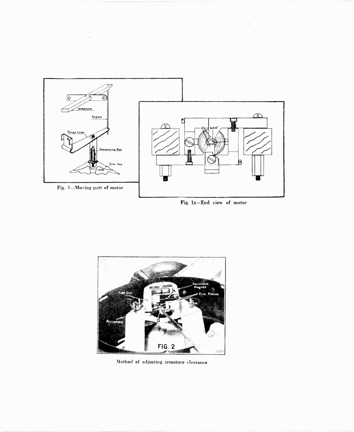
3. Place the thrust lever in position and screw it in place "d", Figure 2, but, do
not solder to the stylus at this time.
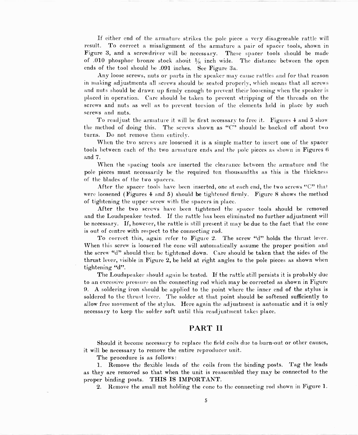
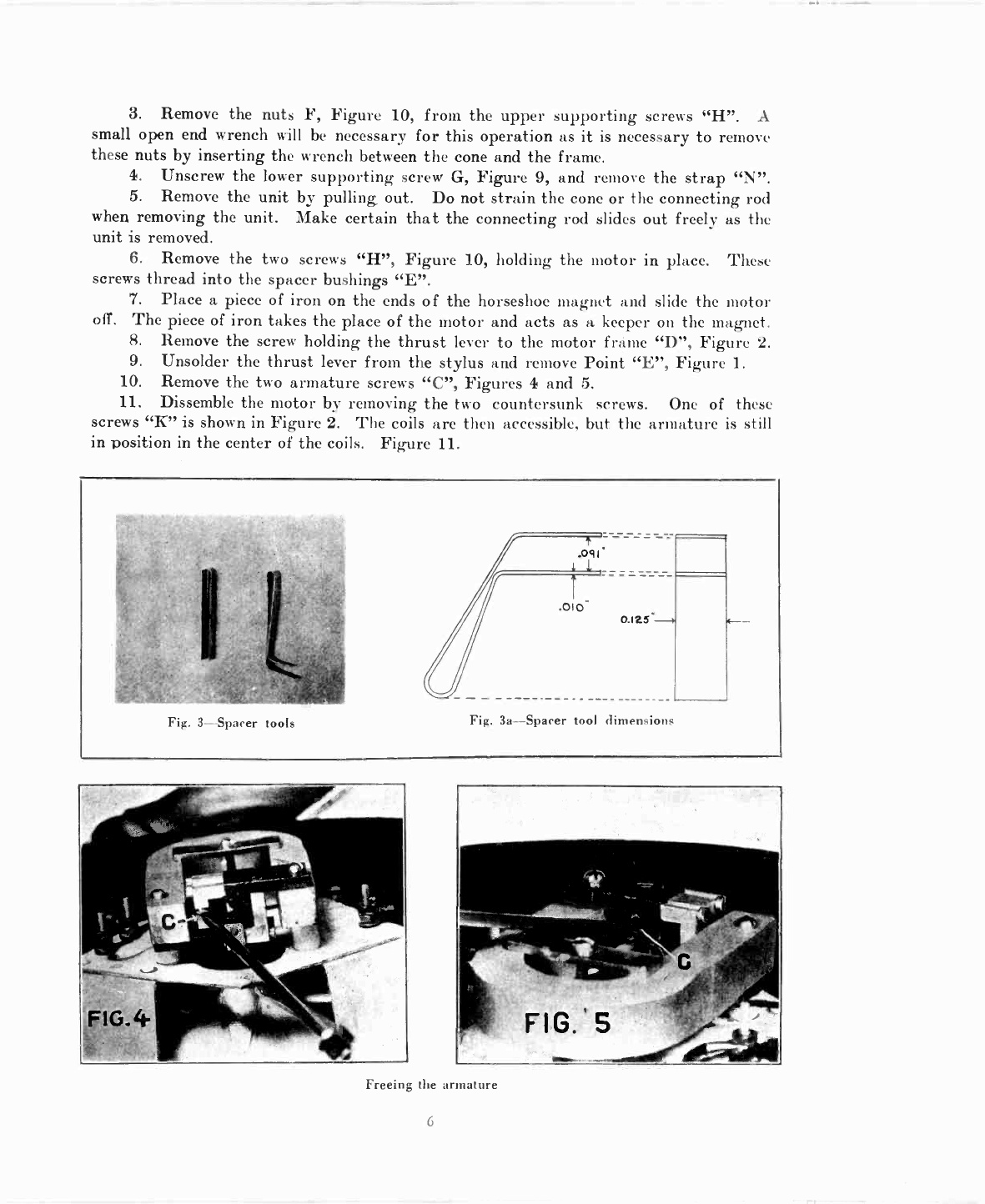
4. Replace the armature screws "C", Figures 4 and 5, but do not seat them firmly.
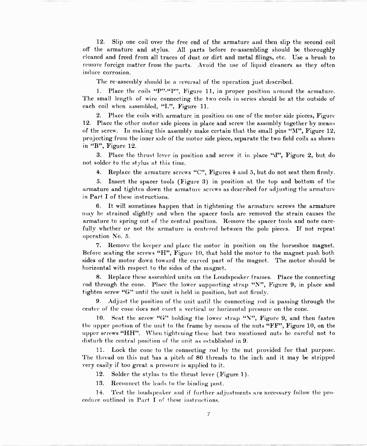
5. Insert the spacer tools (Figure 3) in position at the top and bottom of the
armature and tighten down the armature screws as described for adjusting the armature
in Part I of these instructions.
6. It will sometimes happen that in tightening the armature screws the armature
may be strained slightly and when the spacer tools are removed the strain causes the
armature to spring out of the central position. Remove the spacer tools and note care-
fully whether or not the armature is centered between the pole pieces. If not repeat
operation No. 5.
7. Remove the keeper and place the motor in position on the horseshoe magnet.
Before seating the screws "H", Figure 10, that hold the motor to the magnet push both
sides of the motor down toward the curved part of the magnet. The motor should be
horizontal with respect to the sides of the magnet.
8. Replace these assembled units on the Loudspeaker frames. Place the connecting
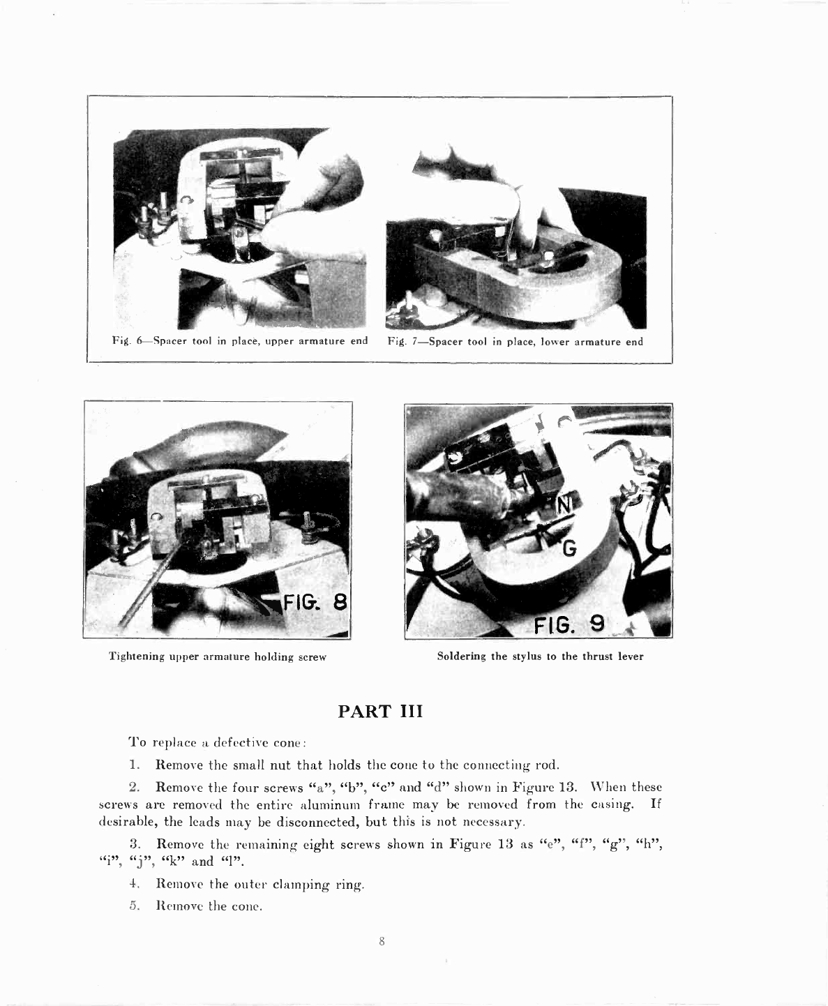
rod through the cone. Place the lower supporting strap "N", Figure 9, in place and
tighten screw "G" until the unit is held in position, but not firmly.
9. Adjust the position of the unit until the connecting rod in passing through the
center of the cone does not exert a vertical or horizontal pressure on the cone.
10. Seat the screw "G" holding the lower strap "N", Figure 9, and then fasten
the upper portion of the unit to the frame by means of the nuts "FF", Figure 10, on the
upper screws "HH". When tightening these last two mentioned nuts be careful not to
disturb the central position of the unit as established in 9.
11. Lock the cone to the connecting rod by the nut provided for that purpose.
The thread on this nut has a pitch of 80 threads to the inch and it may be stripped
very easily if too great a pressure is applied to it.
12. Solder the stylus to the thrust lever (Figure 1).
13. Reconnect the leads to the binding post.
14. Test the loudspeaker and if further adjustments are necessary follow the pro-
cedure outlined in Part I of these instructions.
7
www.americanradiohistory.com

Fig. 6-Spacer tool in place. upper armature end Fig. 7-Spacer tool in place, lower armature end
Tightening upper armature holding screw
PART III
Soldering the stylus to the thrust lever
'l'o replace a defective cone:
1. Remove the small nut that holds the cone to the connecting rod.
2. Remove the four screws "a", "b", "c and "d" shown in Figure 13. When these
screws are removed the entire aluminum frame may be removed from the casing. If
desirable, the leads may be disconnected, but this is not necessary.
3. Remove the remaining eight screws shown in Figure 13 as
"k" and "1".
J
4. Remove the outer clamping ring.
5. Remove the cone.
8
www.americanradiohistory.com

6. Put new cone in place. Make certain that the connecting rod passes through
the center hole in the aluminum cone cap.
7. Place. the cone and outside clamping ring so that all screw holes correspond
with the screw holes in the casing.
8. Replace the screws, "e", "f", "g", "h", "i", "j", "k" and "1" (Figure 13). These
screws should be tightened down uniformly. Do not seat one screw at a time, but tighten
each little by little until all are seated properly.
9. Provide supports and lay the casing on them in a horizontal position.
10. Allow the aluminum frame to rest on the four cleats "O", Figure 13, on the
front edge of the casing.
11. Center the frame in the center of the casing and replace the four screws "a",
"b", "c", "d", Figure 13.
12. Test the speaker and make final adjustments.
While making these adjustments the loudspeaker should be kept in a clean place
free from dirt or filings. Small particles of metal are easily attracted to the mechanism
in the loudspeaker due to its magnetic qualities.
Motor and connection to cone
Motor side piece showing separator pins
9
Coils in place around armature
Frame, front view
www.americanradiohistory.com

Fig. 14
Cylindrical filter type
lo
Fig. 15
Square filter type
www.americanradiohistory.com

Telephone
Tips
CONTINUITY DIAGRAM
MODEL 100 LOUD SPEAKER
FIG. 16
PART IV
Continuity and Filter Tests
Coils of
Reproducer Unit
There are two types of filters appearing in the Model 100 Loudspeaker, one con-
tained in a cylinder and the other in a square box. Both of these filters are electrically
identical, the only difference being in the type of container employed.
In the model employing the cylindrical type of filter (Fig. 14) the input leads
(phone tips) are connected to the two binding posts at A and B on the frame. In the
square filter type (Fig. 15), however, one of the phone tips is soldered to point A and
taped, the other being connected to the binding post at B.
The only equipment required to test the electrical circuit of Model 100 Loudspeaker
is a pair of head phones connected in series with a 41/2-volt C battery. The test points
are shown in capital letters in the circuit diagram and illustrations, Figs. 14, 15 and 16.
Before starting the "click" test, disconnect terminal D from the binding post at B.
This free terminal D will then become a separate test point. In case terminal A is
a taped connection, as it is in the sqúare box filter type of Model 100 Loudspeaker, the
tape will have to be temporarily removed to expose the metallic surface for the "click"
test. Remove loudspeaker plug from radio receiver jack before proceeding with test.
CONTACT POINTS
A to D
AtoC
C to D
C to B
CORRECT EFFECT
Click, closed thru filter coil and reproducer coi
Click, closed thru filter coil.
Click, closed thru reproducer coils.
No click, open thru filter condenser.
A to B No click, open thru filter coil and condenser.
DE.EECT
ls. Open in circuit.
Open filter coil.
Open reproducer coil.
Filter condenser or tele-
phone plug shorted.
Filter condenser or tele-
phone plug shorted.
NOTE.-Care should be taken to replace terminal D on binding post at B after completion
of "click" test.
www.americanradiohistory.com

www.americanradiohistory.com

RCA LOUDSPEAKER
MODEL 100A
SERVICE NOTES
100A-1
Firnt Edition-June, 1927
RCA Loudspeaker Model 100A
RADIO CORPORATION OF AMERICA
Prepared by
Service Division of the Production and Service Department
233 Broadway, New York City
326 Broadway
New York City
DISTRICT SERVICE STATIONS
1412 Monroe Street, N. W. 2001 West Pershing Road 274 Brannan Street
Washington, D. C. Chicago, Ill. San Francisco, Cal.
www.americanradiohistory.com

A WORD OR TWO ABOUT SERVICE
Service goes hand in hand with sales. The well informed RCA Dealer renders serv-
ice at time of sale in affording information as to proper installation and upkeep.
Subsequent service and repair may be required by reason of wear and tear and mis-
handling, to the end that RCA Loudspeaker or Radiola owners may be entirely satisfied.
Obviously this service can best be rendered at point of contact and therefore Deal-
ers and Distributors who are properly equipped with a knowledge of the design and
operation of RCA Loudspeakers and Radiolas occupy a favorable position to contract
for this work.
To assist in promoting this phase of the Dealers business the Service Division of
the RCA has prepared a series of Service Notes-of which this booklet is a part-
containing technical information and practical helps in servicing RCA Loudspeakers
and Radiolas.
This information has been compiled from experience with RCA Dealers' service
problems, and presents the best practice in dealing with them. A careful reading of
these Service Notes will establish their value to Dealer and Distributor, and it is sug-
gested they be preserved for ready reference.
In addition to supplying the Service Notes the RCA, through its Service Stations,
has available to Dealer and Distributor the services of engineers who are qualified to
render valuable help in solving service problems.
Property of Radio Corporation of America. Confidential and to be used only by its
authorized distributors and dealers in furnishing service in connection with its apparatus.
Copyright 1927-Radio Corporation of America.
www.americanradiohistory.com

CONTENTS Page
A Word or Two About Service - 2
Introduction - 5
PART I-SERVICE DATA
Receiver Output - 6
Procedure to Remove Housing - 6
Foreign Material Interfering with Armature Action - 7
Armature Striking Pole Pieces 7
Cone Not Properly Adjusted - 8
Loose Thrust Lever, Nuts and Screws 9
Filter Unit and Magnet Coil Tests - 9
Filter Unit Continuity Test - - - - 9
Continuity Test for Magnet Coils and Loudspeaker Cord 10
Testing Loudspeaker Cord and Loudspeaker Connections 10
Service Data Chart - - - - - 15
PART II-MAKING REPLACEMENTS
Replacing Magnet Coils - - - - - 11
Replacing Armature and Drive Pin - - - 12
Replacing Thrust Lever and Driving Rod to Cone - - - 13
Replacing Motor Assembly Complete 13
Replacing Cones - - - 13
Replacing Filter Units - 14
Replacing Front or Rear Grille - 14
Refitting Grille Cloth - - 14
ILLUSTRATIONS
RCA Loudspeaker 100A 1
Plan View - - 4
Output Transformer 5
Removal of Mechanism Assembly from Housing 6
Armature Spacer Tools - 7
Armature Adjustment - 8
Adjusting the Drive Pin Thrust Lever Connection 9
Removing Cone - 10
Schematic Circuit 11
Units Dismounted 12
Motor Mechanism Partly Exploded 13
www.americanradiohistory.com

RCA LOUDSPEAKER MODEL 100A
MAGNET COILS
THRUST LEVER
SOFT SOLDER
(MAKE ADJUSTMENTS
WITH SOLDERING IRON)
SILVER SOLDER
DRIVE PIN
DRIVING ROD
CONE
SEATING
NUT
CONE
Figure 1 Diagram showing constructional details and operating principle of RC.-1
Loudspeaker 100A
www.americanradiohistory.com

SERVICE NOTES
RCA LOUDSPEAKER MODEL 100A
Prepared by
RCA SERVICE DIVISION
100A-1
INTRODUCTION
RCA Loudspeaker, Model 100A is a new type of loudspeaker operating on the cone
principle and especially designed for use with Radiolas and standard receivers. An
inspection of the interior mechanism reveals a compact unit of rugged construction and
simplicity of design. The loudspeaker consists essentially of a cast metal housing with
an ornamental grille at the front and back, a cone, frame, magnet, motor mechanism
and filter unit. The four screws on the front of the housing support the grille and
mechanism assembly on the inside. This method of mounting provides easy access to
the different parts.
When Loudspeaker Model 100A is used in conjunction with receivers using plate
voltages passing current in excess of 10 milliamperes some method of coupling the out-
put of the receiver to the Loudspeaker should be employed. A choke and condenser
arrangement or an output transformer of proper design will function satisfactorily
for this purpose. Figure 2 illustrates the correct connections for employing either of
these methods.
The service data contained in the present text deals with the problems of imper-
fect loudspeaker reproduction generally and the cause and cure specifically as it applies
to RCA Loudspeaker 100A, The simple and rugged design of RCA Loudspeaker
100A makes it practically trouble proof and permits easy and simple adjustment or
replacement when necessary.
4To S MFDS PLATE
PLATE
30-HEURT[
OR MORE- 11111 To
NOT OVER 11111
i000-ows IIIII
ei LOUD-
SPEAKER
DC.RE5i5T- 111111¡
ANGE b
-ßo
Figure 2-Typical output circuits
To
LOUD-
SPEAKER
www.americanradiohistory.com

PART I-SERVICE DATA
The service problems of loudspeakers deal with conditions evidenced by weak repro-
duction, no reproduction, distortion, noise and rattle. These conditions and their at-
tending causes, while not common to Loudspeaker 100A, are explained in the following
text, and remedies noted so that service men may be provided with helpful information
in any service work that may be required on Loudspeaker 100A.
Figure 3-Removing mechanism assembly from housing
(1) RECEIVER OUTPUT
Before inspecting the loudspeaker for imperfect reproduction check the receiver
output with headphones. Any distortion in the receiver will be faithfully reproduced
in the loudspeaker. If a signal of good quality and volume is being delivered by the
receiver the loudspeaker will have to be examined for the cause of any imperfect repro-
duction that may occur.
(2) PROCEDURE TO REMOVE HOUSING
To examine Loudspeaker 100A the mechanism assembly must be removed from
the housing. This is accomplished by removing the four screws and the fibre sheet at
the bottom of the housing. Then supporting the mechanism assembly inside of the
housing with one hand loosen the four screws that hold the front grille in place. These
screws also fasten the mechanism assembly. After removing the screws the unit can be
lifted clear of the housing, Figure 3. The cord should be pulled inside of the housing
sufficiently to allow enough slack for this operation. The cone and motor mechanism
is now readily accessible for any inspection or adjustment that may be necessary.
6
www.americanradiohistory.com

(3) FOREIGN MATERIAL INTERFERING WITH ARMATURE
ACTION
An inspection of the armature will generally disclose any foreign matter interfer-
ing with the armature action resulting in poor reproduction. A small piece of heavy
paper or a piece of copper or brass not over .010" thick may be used between the arma-
ture and pole piece to remove dirt, dust or other interfering substance. The spacer
tool, described in Section 4, may also be used for this purpose.
Ñ
Y
Figure 4-General appearance and correct dimensions of armature spacing
tools
(4) ARMATURE STRIKING POLE PIECES
Distortion and rattle may be caused by the armature striking either or both of
the pole pieces. This is generally determined by inspection, though in some cases the
contact may be so slight it may be necessary to adjust the armature to check on this
condition. In any case an adjustment of the armature is necessary.
To adjust the armature a set of spacer tools are necessary. Figure 4 illustrates
the general appearance and correct dimensions of these spacer tools. The stock-
obtainable on the open market-should be phosphorous bronze strip .010" thick and
.25" wide. It is bent as illustrated and soldered to hold the opening fairly rigid. The
two ends are tapered as illustrated to a .15" width at their extremities.
Two of these tools are necessary when adjusting the armature. Place one tool in
the space between the armature and pole piece of the motor mechanism at the end next
to the filter unit. This is shown in Figure 5. The other tool is placed at the other end
of the armature a little to one side in order to clear the drive pin located at this end of
the armature. By loosening screws A and B, Figure 5, any tension in either direction
7
www.americanradiohistory.com

that may have been on the armature is released and the spacer tools will provide the
correct clearance or spacing. Now while the spacer tools are in place a hot soldering
iron is applied to the drive pin thrust lever connection point C, Figure 6, and the solder
heated sufficiently to allow the drive pin to find its normal position with regard to the
thrust lever. The iron is now removed. Screws A and B, Figure 5, are tightened and
the spacer tools removed. The armature is now correctly aligned and balanced so that
no abnormal strain is being imposed upon it in any direction.
Figure 5-Armature bracket adjusting screws A and B
(5) CONE NOT PROPERLY ADJUSTED
In some cases a cone may become improperly aligned or adjusjed, causing a strain
to be placed on the driving rod, due to the cone not centering or seating properly.
Poor reproduction is the result and inspection of the armature drive-pin may indicate
a slight torque or twist. This is most likely to occur when replacing a cone. The new
cone should be carefully seated by placing the cone over the driving rod and adjusting
the cone seating nut located on driving rod next to thrust lever (See Figure 1, page 4).
Then attach cone lock nut and washer lightly on inside of cone before fastening the
edge of cone. The holes on the edge of the cone can now be lined up with those of the
metal frame and the outside ring lightly attached with screws and nuts. The cone lock
nut is then tightened and sealed in place with ordinary sealing wax so that the vibration
of the cone will not cause it to loosen. This nut can best be tightened by means of a
small socket wrench made to fit a 3/16" hex. nut (Stevens "Spintite" No. 3 can be
used). The six screws at the outside edge are then seated properly. In doing this
take up on each screw a little at a time causing a gradual seating of the screws.
8
www.americanradiohistory.com
This manual suits for next models
2
Table of contents
Popular Speakers manuals by other brands

Bose
Bose FreeSpace DS 100SE Technical data sheet

Dell
Dell AY511 user guide

Federal Signal Corporation
Federal Signal Corporation BP350S Installation and operating instructions

OXA
OXA Mini Bluetooth Speaker user manual

Imagine
Imagine AMAZON ECHO DOT 3RD GEN Product details

Samsung
Samsung MXT50/ZA Full manual