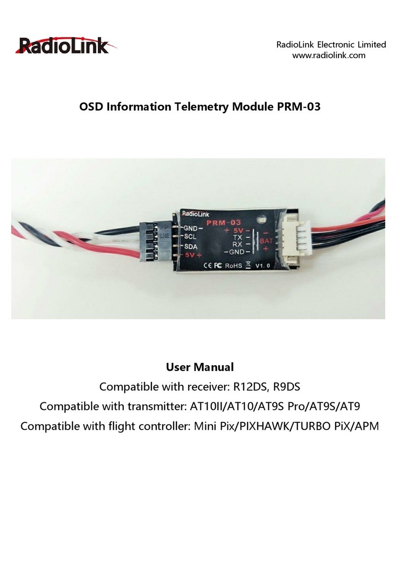
RadioLink Mini Pix User manual

1
Radiolink Mini Pix
(setup for multicopter)
User Manual
Technical updates and additional programming examples available at: http://www.
radiolink.com
This manual is based on the ARDUPILOT, add some introductions about how to setup with
transmitter AT9S, more details about how to use flight controller PIXHAWK-series can from this
website: http://ardupilot.org/copter/docs/initial-setup.html
Please start here for getting service if you have any questions during using the MINI PIX.
www.radiolink.com
Phone: +86-755-88361717-882
Email: after_service@radiolink.com.cn/after_service1@radiolink.com.cn

2
CONTENTS
1. Mini Pix Introduction....................................................................................................................................... 3
1.1 Spare Parts................................................................................................................................................ 3
1.2 Connectors and Parameters..................................................................................................................... 4
1.3 Warning..................................................................................................................................................... 6
2. Mission Planner ............................................................................................................................................... 6
2.1 Install Mission Planner ............................................................................................................................. 6
2.2 Misson Planner Introduction.................................................................................................................... 8
3. Initial Setup...................................................................................................................................................... 8
3.1 Download and Install Firmware................................................................................................................. 8
3.2 Frame Type.............................................................................................................................................. 11
3.3 Accelerometer Calibration ...................................................................................................................... 12
3.4 Compass Calibration................................................................................................................................ 16
3.5 Radio Calibration ..................................................................................................................................... 20
3.6 Flight Modes………………………………………………………………………………………………………………………….……………25
3.6.1 Stabilize Mode.................................................................................................................................. 27
3.6.2 Acro Mode(FPV)............................................................................................................................... 28
3.6.3 Altitude Hold Mode ......................................................................................................................... 29
3.6.4 Auto Mode....................................................................................................................................... 30
3.6.5 PosHold Mode ................................................................................................................................. 32
3.6.6 RTL Mode......................................................................................................................................... 33
3.6.7 Simple and Super Simple Modes..................................................................................................... 35
3.6.8 More Flight Mode............................................................................................................................ 38
4. FailSafe Setting .............................................................................................................................................. 39
4.1 Radio FailSafe setup................................................................................................................................ 39
4.2 EKF FailSafe( Firmware MPV3.2.1+) ....................................................................................................... 44
5. Optional Hardware Setup............................................................................................................................. 45
5.1 Install Mini Pix on Drone ......................................................................................................................... 45
5.2 Connect the Spare Parts.......................................................................................................................... 48
5.3 Arming and Disarming………………………………………………………………………………………………………………………..51
5.4 ESC Calibration(first flight) ....................................................................................................................... 55
5.5 Calibrate Level ........................................................................................................................................ 57
5.6 Geofence ................................................................................................................................................. 57
6. AutoTune…………………………………………………………………………………………………………………………………….…………..61
7. Download DataFlash Log………………………………………………………………………………………….……………….…...............64

3
1. Mini Pix Introduction
Radiolink mini PIX, with STM32F405VGT6 processor and LPS22HB barometer from America ST,
MPU6500 accelerometer from INVENSENS, QMC5883L compass which same technology as
HMC5983 from Honeywell, is your best choice that with top configuration and affordable price.
Shell completely closed to protect, prevent the interaction effects of air current wake on air
pressure when flight. The main board has air pressure vent to ensure the accuracy of the barometer
testing. Shell design and vibration damping by software make Radiolink mini PIX achieved better
Altitude Hold effect.
Based on the mature research and development of PIXHAWK, we take about one year to reanalyze
and retest all the functions of all the models including fixed wing, multicopter and helicopter, make
vibration damping by software to achieve better Altitude Hold effect come true. All the planes
including helicopters, fixed wings and drones no need to add mounting frame.
1.1 Spare Parts

4
1.2 Connectors

5
Parameters

6
1.3 Warning
Warning!!!
This product is not a toy and is not suitable for children under the age of 18. Adults should keep
the product out of the reach of children and exercise caution when operating this product in the
presence of children.
Please don't fly in the rain!
For the users who is the first time to use mini PIX, we suggest that you use it follow these steps:
1. You have to install the mission planner and driver from here and familiar with the menu.
Download the latest Mission Planner from here: http://radiolink.com.cn/doce/product-detail-
133.html
Download the driver form here: https://www.microsoft.com/net/download/dotnet-framework-
runtime/net462
2. To establish a connection you must first choose the communication method/channel you want to
use, and then set up the physical hardware and Windows device drivers. You can connect the PC and
autopilot using USB cables, Telemetry Radios, Bluetooth, IP connections etc.
3. Download the update firmware by USB cable if you need.
4. Connect Mission Planner to AutoPilot, and then connect receiver to AutoPilot to finish the
calibration of transmitter, Accelerometer and compass.
5. Setup RC transmitter flight mode.
6. Assemble aircraft and finish the pre-flight checklist.
7. PID usage.
8. Advanced configuration.
2. Mission Planner
This section contains articles about Mission Planning; creating automated missions that will run
when the ArduPilot is set to AUTO mode.
2.1 Install Mission Planner
Install Mission Planner need download Net Framework 4.6.2 first, you can download form here:
.net4.6.C2 download website
Install Mission Planner after finished Net Framework installation: Mini Pix Mission Planner Download
website : https://www.microsoft.com/net/download/thank-you/net462

8
2.2 Mission Planner Introduction
Once installation is complete, open Mission Planner by clicking on its system icon.
Finish Mission Planner and drive installation, there will several hints when you open the MP at the
first time. The first hint clicks Yes and the others click NO.
There are six Menu Button in main menu.
FLIGHTDATA: flight attitude and data will show in real time on MP
FLIGHTPLAN: planning the flight mission
INTIAL SETUP: for firmware installation and update, Mandatory Hardware and Optional Hardware
setup
CONFIG/TUNING: including detailed PID setup and parameters change
SIMULATION: make MINI PIX work as a simulator after upgrade a special simulation firmware
HELP: you can get help when you have questions about MP
3. Initial Setup
First, you have to upgrade the firmware you need when you the first time ready to use MINI PIX.
Radiolink Mini Pix is default with quadcopter firmware, you have to install the right firmware if you
use the other frame drone.
3.1 Download and Install Firmware
Please connect your Mini Pix and computer via USB cable. Open the Mission Planner and select the
right COM port drop-down on the upper-right corner of the screen (near the Connect button). Make
sure the Baud rate is 115200 as shown.

9
Attention:
(1) Do not click CONNECT before you upload the new firmware, please click DISCONNECT if you
have connected successful before. Upload new firmware will be not success if you have
connected already.
(2) Please do not upload new firmware by wireless data transmission because it has missed the
reset signal.
(3) If there’s without firmware version number, it means failed upload new firmware. It may
cause of network problem, please re-upgrade firmware until shows the version.
Click “Yes” to install the firmware,
Disconnect the USB cable, click OK and then reconnect USB cable immediately (Pay attention:
Mini Pix will have failed to connect if there are more than one COM, please remove other
equipment if disconnect).
Red status LED means the MINI PIX is loading the firmware.

10
After upgrade firmware 3.1 or after version 3.1, it will pops up a warning box that shows motors will
run at idle speed after disarmed.
Please click “CONNECT” to connect your Mini Pix and computer when firmware has installed
successful.
Click “CONNECT” and it turns to green means connect successful.
Pay attention:
Please set Layout from “Basic” to “Advanced” in CONFIG/TUNING menu if comes out three
questions as below when you installing the Mission Planner.

11
(1) It takes a long time to read the parameters.
(2) There are not have “Load custom firmware” and “Pick previous firmware”.
(3) INITIAL SETUP menu missed some parameters.
3.2 Frame Type
Please setup as below:

12
1. INITIAL SETUP
2. Mandatory Hardware->Frame Type
3. Choose Quad or Hexa or other frame types as you need
3.3 Accelerometer Calibration
Make sure the Mini Pix is keeping horizontal when do the accel calibration.
1. Place vehicle level and press any key to save setting.

13
2. Place vehicle on its LEFT side and press any key to save setting.
3. Place vehicle on its RIGHT side and press any key to save setting.

14
4. Place vehicle DOWN and press any key to save setting.

15
5. Place vehicle UP and press any key to save setting.
6. Place vehicle on its BACK and press any key to save setting.

16
3.4 Compass Calibration
There are two situations about compass calibration:
1. Without GPS, use internal compass.
Calibrate interface will shows Externally mounted is None, then click “Start” and turn Mini Pix till
the progress bar of Mag 1 to the end and comes out the MAG_CAL_SUCCESS marked words.
2. with GPS, use external and internal compass.
Calibrate interface will shows as picture below when use with GPS.
If the GPS mounted with the same direction with flight controller, then it need not to setup the direction of
GPS in MP but if you mounted the GPS with the different direction of MINI PIX, you have to setup in the MP.

17
Compass calibrate Positioning Indicate
Please use Mission Planner
Arrows shows the front, point to the Humanized positioning green LED indicate.
same direction as the flight controller. The green LED will flicker when TS100 have
Keep the same direction with flight controller. positioning.
Please fixed Mini Pix and TS100, then click “Start” and turn Mini Pix and TS100 till the progress bar
of Mag 1 and 2 to the end and comes out the MAG_CAL_SUCCESS marked words.

18
Calibrate the compass as these steps below:
Hold the vehicle in the air and rotate it slowly so that each side (front, back, left, right, top and
bottom) points down towards the earth for a few seconds in turn.

19
The mission planner will keep recording the data that collected by the compass sensor and the
progress bar and the percentage will keep change when you calibrate the compass, if the
percentage have not changed, please check if the compass is connect success.
The mission planner will remind you when the compass has calibrated success.
Click OK and then reconnect MINI PIX to computer, compass calibrate success after restart the MINI
PIX.
Attention:
1. when the progress bar moves to 100 and then restart from 0, it may because of the wrong
calibrate action or interference. You can have a try to calibrate again till compass calibrate success,
or setup the Fitness is Relaxed and recalibrate.

20
3.5 Radio Calibration
This article shows how to perform radio control calibration using
Mission Planner
.
RC transmitters are used to control vehicle movement and orientation. Copter and Plane minimally
control throttle, pitch, roll and yaw, while on Rover we just control throttle and roll. Each of these
control signals are mapped to transmitter stick/switch(s) and in turn to autopilot channels from the
connected receiver.
Calibrating each of the transmitter controls/channels is a straightforward process - simply move
each of the enabled sticks/switches through their full range and record the maximum and minimum
positions.
There are two main transmitter configurations:
Mode 1: left stick controls pitch and yaw, the right stick will control throttle and roll.
Mode 2: left stick controls throttle and yaw; the right stick will control pitch and roll.
Copter default channel mappings are:
Channel 1: Roll
Channel 2: Pitch
Channel 3: Throttle
Channel 4: Yaw
Channel 5: Flight modes
Channel 6: (Optional) In flight tuning or camera mount (mapped to transmitter tuning knob)
Unused channels can be mapped to control additional peripherals.
This manual suits for next models
2
Table of contents
Other RadioLink Control Unit manuals
Popular Control Unit manuals by other brands

Comelit
Comelit 20004605 Technical manual

Wallbox
Wallbox Commander 2 installation guide

Bosch
Bosch MS 6 manual

Microchip Technology
Microchip Technology RN4870 manual

Hanwha Vision
Hanwha Vision SPA-D2000 quick guide

Franklin Electric
Franklin Electric SubStart3P SS037P3 Installation and operation instructions