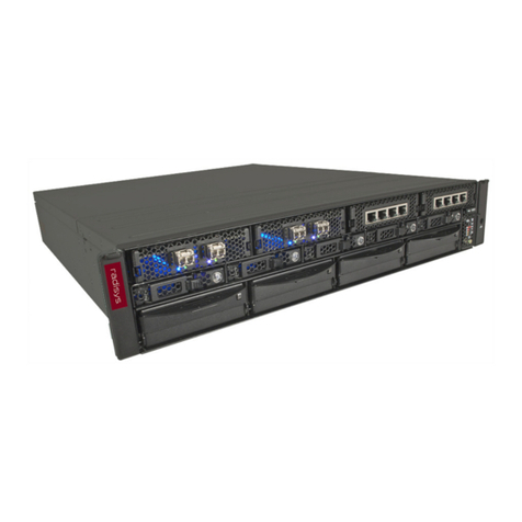
RadiSys ATCA-5400 RTM Service manual

www.radisys.com
PROMENTUM®
REAR TRANSITION MODULE
REFERENCE
ATCA-5400
007-03301-0000 • August 2009

2
Release Date Description
-0000 August 2009 First release.
Copyright © 2009 by RadiSys Corporation. All rights reserved.
RadiSys and Promentum are registered trademarks of RadiSys Corporation. AdvancedTCA, ATCA, and PIGMG are registered
trademarks of PCI Industrial Computer Manufacturers Group. LSI Logic is a registered trademark of LSI Logic Corporation.
All other trademarks, registered trademarks, service marks, and trade names are the property of their respective owners.

3
TABLE OF CONTENTS
Preface ................................................................................................................................................................ 5
About this manual....................................................................................................................................................................... 5
Notational conventions.............................................................................................................................................................. 5
Where to get more product information ............................................................................................................................... 6
Related Promentum manuals ..............................................................................................................................................................6
Standards information...........................................................................................................................................................................6
Other related documents......................................................................................................................................................................6
Electrostatic discharge ................................................................................................................................................................ 7
Chapter 1: Product Overview........................................................................................................................... 9
Block diagram............................................................................................................................................................................... 9
RTM overview..............................................................................................................................................................................10
Chapter 2: Installing FRUs.............................................................................................................................. 11
Installing SFPs..............................................................................................................................................................................11
Configuration recommendations..................................................................................................................................................... 11
Transceiver installation ....................................................................................................................................................................... 11
Filler plug installation.......................................................................................................................................................................... 12
Installing a hard disk drive....................................................................................................................................................... 12
Updating the drive information record........................................................................................................................................... 12
Attaching the drive sled to the HDD ............................................................................................................................................... 13
Mounting the hard disk drive and sled onto the RTM ................................................................................................................ 14
Inserting the RTM into the chassis................................................................................................................................................... 14
Chapter 3: Configuring a Redundant Disk Array ........................................................................................ 15
Supported RAID configurations ............................................................................................................................................. 15
Preparing hard disk drives to participate in an array..........................................................................................................16
Configuring a hard disk drive array in the SAS BIOS .........................................................................................................17

4
Table of Contents
Chapter 4: LEDs and External Interfaces...................................................................................................... 19
Face plate interfaces ..................................................................................................................................................................19
LEDs........................................................................................................................................................................................................ 20
Face plate connectors......................................................................................................................................................................... 21
Reset button.......................................................................................................................................................................................... 21
Zone 3 interface.........................................................................................................................................................................22
Alignment keys..................................................................................................................................................................................... 23
Chapter 5: Components and Subsystems....................................................................................................25
SAS/SATA controller ..................................................................................................................................................................25
Hard disk drive...........................................................................................................................................................................25
Hardware management...........................................................................................................................................................26
Hot swap................................................................................................................................................................................................ 26
Reset ....................................................................................................................................................................................................... 27
Connectivity records for interface compatibility ........................................................................................................................... 27
Upgradeable components.......................................................................................................................................................27
Appendix A: Specifications ............................................................................................................................. 29
Environmental specifications ..................................................................................................................................................29
Safety specifications..................................................................................................................................................................30
Mechanical dimensions ........................................................................................................................................................... 30
Electromagnetic compatibility (EMC) ................................................................................................................................... 31
Power consumption..................................................................................................................................................................32
Mean time between failures (MTBF)....................................................................................................................................33
Environmental assumptions.............................................................................................................................................................. 33
General assumptions .......................................................................................................................................................................... 33
General notes ....................................................................................................................................................................................... 33
Appendix B: IPMI Commands and Managed Sensors ...............................................................................35
Supported IPMI commands....................................................................................................................................................35
Managed sensors ......................................................................................................................................................................36
Types of sensors .................................................................................................................................................................................. 36
Supported sensors............................................................................................................................................................................... 37

5
PREFACE
About this manual
This manual describes the Promentum®ATCA-5400, a rear transition module (RTM) that is fully
compliant with AdvancedTCA®(PICMG 3.0 Advanced Telecommunications Computing
Architecture R3.0). The RTM is designed to mate with a compatible front module, such as the
ATCA-4500 Compute Processing Module, in high availability (HA) systems like the Promentum
SYS-6010 platform.
Use this manual as a reference for the operation and maintenance of the RTM. The material
presented here is not introductory; it is assumed that you are already familiar with the intended
use of the RTM in your organization’s ATCA platform.
For instructions on installing optional components into the RTM, see Chapter 2, Installing FRUs,
on page 11. For instructions on installing the RTM into the shelf, see the ATCA-4500 Compute
Processing Module Installation Guide.
The simplified name of “RTM” will be used in place of “ATCA-5400” for the rest of the manual.
The simplified name of “CPM” will be used in place of “Compute Processing Module” or
“ATCA-4500” for the rest of the manual.
Notational conventions
This manual uses the following conventions
All numbers are decimal unless otherwise stated.
ItalicText File, function, and utility names.
MonoText Screen text and syntax strings.
BoldMonoText A command to enter.
ItalicMonoText Variable parameters.
Brackets [ ] Command options.
Curly braces { } A grouped list of parameters.
Vertical line | An “OR” in the syntax. Indicates a choice of parameters.

6
Where to get more product information
Please visit the RadiSys Web site at www.radisys.com for product information and other
resources. Downloads (manuals, release notes, and software) are available at
www.radisys.com/downloads.
Related Promentum manuals
The following manuals are available to help you use the RTM and the CPM:
Installation and initial setup instructions. The ATCA-4500 Compute Processing Module
Installation Guide provides the steps for installing the CPM and RTM into a shelf and
completing the initial configuration.
Hardware reference information. The ATCA-4500 Compute Processing Module Reference
describes the module’s hardware features and operation. It also contains information on the
main BIOS configuration, Intelligent Platform Management Interface (IPMI) commands, and
troubleshooting.
Standards information
For information about the PCI Industrial Computer Manufacturers Group (PICMG) and the
AdvancedTCA standard, consult the PICMG Web site at this URL:
http://www.picmg.org
Other related documents
CAN/CSA C22.2 No. 60950-1-03 Safety for Information Technology Equipment, Version 2,
Canadian Standards Association (www.csa.ca), April 1, 2003
EN 60950-1:2002 Information Technology Equipment. Safety. General Requirements,
European Committee for Electrotechnical Standardization (CENELEC) (www.cenelec.eu),
February 22, 2002
IEC 60950-1 Information Technology Equipment - Safety - Part 1: General Requirements, 1st
Edition, International Electrotechnical Commission (www.iec.ch), October 25, 2001
Information Technology - Serial Attached SCSI - 1.1 (SAS-1.1), ANSI/INCITS 417-2006
Integrated RAID for SAS User’s Guide, LSI Logic®Corporation
LSISAS1064E PCI Express to 4-Port Serial Attached SCSI, LSI SAS1064E Revision 2.3, LSI Logic
Corporation, November 2007
Intelligent Platform Management Interface Specification v1.5, Revision 2.0, Intel Corporation;
Hewlett Packard Company, NEC Corporation, and Dell Computer Corporation
PICMG 3.0 Advanced Telecommunications Computing Architecture R3.0, PCI Industrial
Computer Manufacturers Group, March 24, 2008
PICMG 3.1 R1.0 Specification, Ethernet/Fibre Channel for AdvancedTCA Systems, PICMG,
January 22, 2003

Electrostatic discharge
7
PICMG AMC.0 R2.0 Advanced Mezzanine Card Base Specification, PCI Industrial Computer
Manufacturers Group, November 15, 2006
PM8380 QuadSMX 3G Quad SATA/SAS Mux/Demux for 3G, PMC-2031101, Issue 8, PMC-
Sierra, April 2005
Serial ATA Revision 2.5, Serial ATA International Organization, October 27, 2005
Small Form-factor Pluggable (SFP) Transceiver Multisource Agreement (MSA), Cooperation
Agreement for Small Form-Factor Pluggable Transceivers, Agilent Technologies, Blaze Network
Products, E2O Communications, Inc., ExceLight Communications, Finisar Corporation, Fujikura
Technology America Corp., Hitachi Cable, Infineon Technologies Corp., IBM Corp., Lucent
Technologies, Molex, Inc., Optical Communication Products, Inc., Picolight, Inc., Stratos
Lightwave, and Tyco Electronics, September 14, 2000
UL 60950-1 Safety for Information Technology Equipment – Part 1: General Requirements,
Edition 1, Underwriter Laboratories (www.ul.com), April 1, 2003
Electrostatic discharge
WARNING!This product contains static-sensitive components and should be handled with care.
Failure to employ adequate anti-static measures can cause irreparable damage to components.
Electrostatic discharge (ESD) damage can result in partial or complete device failure,
performance degradation, or reduced operating life. To avoid ESD damage, the following
precautions are strongly recommended:
Keep each RTM in its ESD shielding bag until you are ready to install it.
Before touching the RTM, attach an ESD wrist strap to your wrist and connect its other end
to a known ground.
Handle the RTM only in an area that has its working surfaces, floor coverings, and chairs
connected to a known ground.
Hold the RTM only by its edge and mounting hardware. Avoid touching PCB components
and connector pins.
For further information on ESD, visit www.esda.org.

8

9
1
PRODUCT OVERVIEW
This chapter briefly describes the ATCA-5400 RTM.
Block diagram
Figure 1. ATCA-5400 RTM block diagram
ATCA-5400 RTM
Zone 3
P30
Zone 3
P31
+12_RTM
+3_3_MP
RTM_PRESENT
Note: Zone 3 pins
that are not shown
are not connected.
RTM_EN *
IPMB-L
USB
JTAG _TCK
JTAG _TDI
JTAG _TDO
JTAG _TM S
JTAG _TRST
SAS 0 [R X,TX] +/-
(f ro m AM C Po rt 2 )
SAS 1 [R X,TX] +/-
(f ro m AM C Po rt 3 )
GE1 [RX,TX]+/-
GE2 [RX,TX]+/-
S
A
S
2
SFP 1
LSI SAS 1064 E
Controller
2. 5" SFF
Drive
3210 01
Alarm
CPLD
SFP port lin k /
status LEDs
USB
Power
Conver sion
& Monitori ng
+3.3V
+1.8V
+5V
+1.2V
MMC
Circuitry
PWR EN (x4 )
EN
CPU0_RTM_RST *
To Alarm CPLD JTAG
PCI e_RST*
x4 PCI e
REF_CLK
PCI E_REFCL K
PCI E_[RX,TX]+/-
RS-232
Buffer
SER0
SFP 2
RTM-L
(from Zone3)
RESET _0
RTM-L To Alarm CPLD
E-Key/
GPIO
Latch
Temp
Sen.
75.00
MHz Clk
37.50
MHz Clk
NVSRAM
FLASH ROM
CLK
Prim a ry
Secondary
Prim a ry
Secondary
CPLD JTAG
SERDES
Buffers w / PE
& EQ contr ol
S
A
S
1
SFP status: present,
LOS, disable, tx fault
SFP 1 I 2C
SFP 2 I 2C
To MMC
Controller
Disk
Controller
Disk
Color Key:
Gigabit Ethernet
SAS /SATA
PCI Expre ss
Powe r
FRU Cold Rst
Board IDs
ATCA LEDs
SFP control
USB OC *
SER Cable det*
PM8380
SAS
Driver
SERIAL_0

1
Product Overview
10
RTM overview
The ATCA-5400 RTM is an optional compatible rear transition module for the ATCA-4500 CPM
front module that supplies the CPM with additional data storage and connectivity options.
The RTM has an on-board SAS/SATA controller and can host an optional SAS hard disk drive
(HDD). The controller can access an HDD AMC if one is installed on the CPM. The RTM also
includes two rear panel SAS ports to allow cable connections to additional hard disk drives, such
as hard disk drives accessible from another RTM. The SAS/SATA controller supports RAID
(redundant array of inexpensive disks), including RAID 0 (striping) and RAID 1 (mirroring)
configurations.
For instructions on installing a hard disk drive, see Installing a hard disk drive on page 12. For
instructions on configuring a RAID, see Chapter 3, Configuring a Redundant Disk Array, on
page 15.
The RTM has two 1-gigabit Ethernet SFP sockets on its face plate that can facilitate external
connections through the RTM to the CPM. These rear Ethernet ports are usable when the
Ethernet controller on the CPM is configured to route the connections to the RTM. On the
ATCA-4500 CPM, a BIOS menu setting determines whether these connections are routed to the
CPM front panel or to the RTM. For instructions on installing SFP transceivers in the SFP sockets,
see Installing SFPs on page 11.
The RS-232 serial port on the RTM provides a management interface to the CPM. The RTM also
includes a USB 2.0 port that connects to the CPM.
A module management controller (MMC) provides intelligent management of the RTM
hardware, including its managed sensors. The MMC responds to reset signals from the CPM as
well as IPMI commands.

11
2
INSTALLING FRUS
Installing SFPs
The RTM has sockets that accept SFP (small form-factor pluggable) transceiver modules. If SFP
transceivers are installed, they can provide external connections to the Ethernet interfaces. The
sockets are located on the face plate of the RTM, as shown in Figure 4 on page 19.
SFP transceivers can be installed on the RTM at any time.
Configuration recommendations
The RTM supports up to two SFP transceivers, with filler plugs installed in unused sockets. For a
list of tested and qualified transceivers, see the Promentum Component Compatibility Report in
the AdvancedTCA downloads section of the RadiSys Web site at www.radisys.com/downloads.
Standard RTM configurations come with SFP filler plugs installed to protect the internal
components of the RTM.
Transceiver installation
The illustration shows the correct orientation for
inserting an SFP transceiver. The transceiver
may vary in appearance, but the same insertion
guidelines should be used.
1. Obey the ESD procedures in Electrostatic
discharge on page 7 and make sure you
are adequately grounded.
2. Remove the RTM and the transceivers from
their antistatic bags.
3. On the RTM face plate, remove the filler
plugs from the sockets where the
transceivers will be installed. For sockets
not being used, keep the filler plugs in
place. The plugs protect the sockets, control
airflow, and prevent electromagnetic
interference.
4. Make sure the latch on the cable end of the
transceiver is closed. This makes the SFP
snap into position when it is inserted into
the socket.
Vertical insertion
Connector
side is down
Cable end
Horizontal insertion
Cable end
Connector
side is on right
Latch in
closed position

2
Installing FRUs
12
5. Hold the transceiver near the cable end and turn the connector side to the correct position
depending on the RTM orientation:
If the RTM is vertical, turn the transceiver so the connector side is on the right.
If the RTM is horizontal, turn the transceiver so the connector side is down.
6. Insert the connector end of the transceiver into the socket.
7. Once inserted into the socket, carefully slide the transceiver until its connector is fully seated
and the SFP snaps into position.
8. Repeat the previous steps for each transceiver being installed.
9. For transceivers with cable plugs installed on their cable end, keep the plugs in place until it
is time to connect cables to the transceivers. The cable plugs protect the internal
components of the transceivers from dust and foreign contaminants.
Note: If an SFP needs to be removed, open the latch and pull the SFP out of the socket.
Filler plug installation
If the SFP transceivers are removed, install either replacement transceivers or filler plugs to
protect the sockets, to control airflow, and to prevent electromagnetic interference.
Installing a hard disk drive
RadiSys ships the RTM without a hard disk drive (HDD) installed. A separate HDD can be
ordered from RadiSys and installed onto the RTM prior to installing the RTM into the shelf. For
information on suitable hard disk drives, see the Promentum Component Compatibility Report
in the AdvancedTCA downloads section of the Web site at www.radisys.com/downloads.
The RTM ships with a sled for sliding the HDD into the correct mounting position on the RTM
(see Figure 2 on page 13). To install the HDD on the RTM, first attach the HDD to the drive sled
with the provided screws and then mount the sled and HDD onto the RTM. The following
sections explain the installation procedure.
Before starting: Get a medium-size Phillips screwdriver and a suitable HDD.
Updating the drive information record
If you are installing a new hard disk drive or replacing an existing one, follow these steps to
ensure that the drive information record for the MMC has the correct hard disk drive type when
the RTM resets after it is inserted into the chassis.
1. Insert the RTM into the rear of the chassis in the slot corresponding to the associated front
module CPM.
2. Update the drive information record in the FRU data with data about the new hard disk drive
to be installed. Enter this rmcpta command:
setdriveinfo
3. Remove the RTM from the chassis and proceed to Attaching the drive sled to the HDD on
page 13.

2
Installing a hard disk drive
13
Attaching the drive sled to the HDD
1. Obey the ESD procedures in Electrostatic discharge on page 7 and make sure you are
adequately grounded.
2. Place the drive sled on a static-free surface with the retaining screw (screw head up) at the
left. See Figure 2.
3. Place the hard disk drive (HDD) component side down on the drive sled with the HDD
SAS/SATA connector at the right.
4. Hold the HDD and drive sled together and turn them upside down to access the screw
holes.
5. Screw the four supplied M3 screws through the sled holes shown in Figure 2 and into the
corresponding holes on the HDD.
6. Turn the HDD and drive sled right-side up so the retaining screw head faces up.
Figure 2. HDD installation
Retaining screw SAS/SATA connector
Mounting screw
Keyhole
SAS/SATA connector
Keyhole screw
Hard disk drive (HDD)
Drive sled

2
Installing FRUs
14
Mounting the hard disk drive and sled onto the RTM
1. Align the four sled keyhole screws over the RTM keyholes and simultaneously guide all four
screws down into the keyholes.
2. Slide the sled along the keyhole slot toward the RTM face plate and then toward the RTM
SAS/SATA connector. See Figure 2 on page 13. The hard disk drive SAS connector mates
with the RTM SAS/SATA connector.
3. Secure the sled to the RTM by tightening the retaining screw with a screwdriver.
Inserting the RTM into the chassis
After the hard disk drive is installed, insert the RTM into the chassis. The MMC will report the
correct drive type because it was previously set in Updating the drive information record on
page 12.

15
3
CONFIGURING A REDUNDANT DISK ARRAY
This chapter explains the RTM’s support for RAID (redundant array of inexpensive disks) and
how to configure a RAID from the available hard disk drives. Hard disk drive arrays can be
configured in the SAS BIOS, which is the BIOS for the SAS/SATA controller. Some hard disk
drives must be connected to the RTM with cables before you can include them in an array.
Supported RAID configurations
The RTM’s SAS/SATA controller supports these RAID levels and configurations:
RAID 1 integrated mirroring (IM), which provides redundancy. Two hard disk drives (a
primary and secondary) must be identified to be used as exact copies. Up to two hot spare
hard disk drives can be included in case one of the copied hard disk drives fails. In case of
failure, the contents of the remaining good hard disk drive can be copied to a hot spare,
which also gets a copy of all new data. The available hard disk drive capacity is the same as
the smallest hard disk drive or spare in the array.
RAID 1 integrated mirroring enhanced (IME), which provides striping and one copy of
each stripe for redundancy. At least 3 hard disk drives must be used, with a maximum of 8
copies. Up to two hot spare hard disk drives can be included in case one of the participating
hard disk drives fails. The available hard disk drive capacity is the smallest disk capacity in
the array multiplied by the number of hard disk drives in the array, and then divided by two.
This is due to the mirrored stripes used in the IME array.
RAID 0 integrated striping (IS), which improves performance. At least 3 hard disk drives
must be identified to participate, with a maximum of 10 hard disk drives. The available hard
disk drive capacity is the capacity of the smallest hard disk drive in the array multiplied by
the number of hard disk drives in the array.
The SAS/SATA controller supports multiple arrays at once, including arrays of different types, as
long as the number of available hard disk drives is sufficient to support the arrays. For additional
information on the supported RAID options, see the Integrated RAID for SAS User’s Guide from
LSI Logic Corporation.

3
Configuring a Redundant Disk Array
16
Preparing hard disk drives to participate in an array
Table 1 identifies the locations of hard disk drives that can be used by the RTM SAS/SATA
controller in an array. It also shows the physical SAS connection that must be present before you
can include the hard disk drive in an array through a SAS BIOS configuration.
Tip: Before configuring an array in the SAS BIOS, you may want to make a copy of any existing
data on the hard disk drives. All existing data is deleted from the hard disk drives that participate
in an IS array. For a hard disk drive that will act as the primary hard disk drive in an IM or IME
array, the SAS BIOS configuration gives you the option to keep existing data on the hard disk
drive. For other hard disk drives in an IM or IME array, any existing data is deleted.
Table 1. Locations and SAS connections for eligible disks
Disk location Connection to the RTM SAS/SATA controller
RTM (with its SAS/SATA controller hosting the RAID) On board (no action required)
HDD AMC on a CPM in the front slot hosting the RTM Zone 3 connectors (no action required)
Another RTM Cable between the SAS 1 ports on each RTM (see
Figure 3 on page 17)
HDD AMC on another CPM in the front slot hosting
another RTM
Cable between the SAS 2 ports on each RTM (see
Figure 3 on page 17)
HDD AMC in bay 1 on an ATCA-45xx CPM in the front slot
hosting an ATCA-5400 RTM
Custom cable from the ATCA-5400 RTM SAS 1 port to
one of the RTM SAS ports
HDD AMC in bay 2 on an ATCA-45xx CPM in the front slot
hosting an ATCA-5400 RTM
Custom cable from the ATCA-5400 RTM SAS 2 port to
one of the RTM SAS ports
Any other hard disk drive or hard disk drive array that can
be connected to the RTM with a cable
Cable from the hard disk drive or hard disk drive
array to a SAS port on the RTM

3
Configuring a hard disk drive array in the SAS BIOS
17
In Figure 3, the top illustration shows the connections between hard disk drives on two RTMs
and the CPMs in the front slots. The bottom illustration shows the connections between a hard
disk drive array and hard disk drives on the RTM, with the CPM in the front slot.
Figure 3. Connections between hard disk drives on two ATCA-5400 RTMs or to a hard disk drive array
Configuring a hard disk drive array in the SAS BIOS
The SAS BIOS can be accessed during the CPM’s boot process, before the main BIOS prompt
appears.
To configure a RAID:
1. Reset the CPM.
2. From the CPM serial console, access the SAS BIOS when you are prompted to press Ctrl-C
to start the LSI configuration utility.
3. The SAS/SATA controller is shown. Select it and press Enter.
Cabled Link
PCB Traces
Custom SAS
Crossover
Standard SAS
Crossover
External hard disk
drive array enclosure
ATCA-4500 CPM
ATCA-5400 RTM
HDD AMC
Port 2
SAS/SATA
controller
Port 1
SAS/SATA
driver
Port 3
0
1
Port 2
Port 0
Port 1
01
0
1
SAS 1
0
1
01
0
1
0
1
01
0
1
Drive enumeration order:
1) Local RTM hard disk drive
2)
Local AMC hard disk drive
3)
Upper SAS connector
4)
Lower SAS connector
Cabled Link
PCB Traces
Port 3
Port 2
Port 0
Port 3
Port 3
Port 2
Port 0
Port 1
Hard disk
drive
SAS 2
SAS 1 SAS 2
Port 2
Port 0
Port 3
Port 1 Port 2
Port 3
SAS/SATA
controller
SAS/SATA
driver
ATCA-4500 CPM
ATCA-5400 RTM HDD AMC
ATCA-4500 CPM
HDD AMC
Port 2
Port 3
Port 1 Port 2
Port 0
Port 3
SAS/SATA
controller
SAS/SATA
driver
Port 3
Port 2
Port 0
Port 1
SAS 1
SAS 2
ATCA-5400 RTM
Drive enumeration order
:
1) Local RTM hard disk drive
2)
Local AMC hard disk drive
3)
Upper SAS connector
4)
Lower SAS connector
Hard disk
drive
Hard disk
drive

3
Configuring a Redundant Disk Array
18
4. Select the RAID Properties option and press Enter.
5. Select the option for the type of RAID to create:
A. Select Create IM Volume to set up a RAID 1 mirroring volume.
Select two RAID hard disk drives to act as the primary and secondary mirror hard disk
drives, and optionally up to two hot spares in case the primary or secondary fails.
The first hard disk drive you select is the primary hard disk drive, which allows the option
to keep existing data. Data on a secondary hard disk drive is deleted.
B. Select Create IME Volume to set up a RAID 1E volume for mirroring with
enhancements.
Select at least three RAID hard disk drives to participate in the array, and up to two hot
spares in case a participating hard disk drive fails.
The first hard disk drive you select is the primary hard disk drive, which allows the option
to keep existing data. Data on each secondary hard disk drive is deleted.
C. Select Create IS Volume to set up a RAID 0 striping volume.
Select at least 3 hard disk drives to include in the array, with a maximum of 10. Data on
each hard disk drive in a striping array is deleted.
Note: When two pairs of RTMs and CPMs are cabled together, the hard disk drives are
identified in the SAS BIOS screens by slot number instead of the SAS/SATA port number.
The identification is as follows:
Slot 0: Local RTM hard disk drive (on the RTM controlling the RAID)
Slot 1: Local HDD AMC hard disk drive
Slot 2: Remote RTM hard disk drive (when a custom crossover cable is used)
Slot 3: Remote HDD AMC hard disk drive (when a custom crossover cable is used)
When a standard crossover cable is used, slots 1 and 2 remain the same but slots 3 and
4 identify an external hard disk drive array.
The slot numbers correspond to the SAS/SATA controller port numbers in Figure 3 on
page 17.
6. Complete the array configuration by pressing C.
7. Save the changes when prompted.
Note: When one array has been configured, use the Manage Array option to view, delete, or
modify the hot spares in the array. When multiple arrays have been configured, use the View
Existing Array option to select and manage an array.
For additional details about using the SAS BIOS screens to create an array, see the Integrated
RAID for SAS User’s Guide from LSI Logic Corporation.

19
4
LEDS AND EXTERNAL INTERFACES
Face plate interfaces
The external interfaces on the RTM face plate include a USB port, two external SAS ports, an
RS-232 serial port, two SFP sockets, and a reset button.
Figure 4 shows the location of the interfaces on the RTM face plate.
Figure 4. RTM face plate
Link status LED
Port status LED
Link status LED
Port status LED SFP sockets (2)
Hot swap LED (H/S)
Out of service LED (OOS)
Power Good LED (PWR)
HDD Activity LED (ACT)
RS-232 serial port
SAS ports (2)
USB port
Reset button

4
LEDs and External Interfaces
20
LEDs
Table 2 describes the face plate LEDs.
Table 2. Face plate LEDs
Label LED ID Definition Color LED explanation and states
OOS LED1 Out of service Red or
amber
a
Controlled by the MMC.
Red or amber: RTM is OOS
Off: RTM is operating normally
PWR LED2 Power good Green Controlled by the MMC.
Green: Power to the RTM is normal
Off: RTM is not powered or in the hot-swap process
ACT LED3 Activity Amber Controlled by the RTM’s HDD.
Blinking: HDD activity
Off: No activity
H/S BLUE LED Hot swap Blue Controlled by the MMC.
Solid: Ready for hot swap
Long blink: Activating the module after insertion
Short blink: Preparing for hot swap
Off: No hot-swap activity in progress
SFP 1,
SFP 2
N/A Link status Green or
amber
Controlled by the alarm CPLD over the RTM-link bus.
Green: 1000BASE connection
Amber: 10/100BASE connection (Copper only)
Solid: Link OK
Blinking: Link activity
Off: Link fail, port disabled
Port status Green or
amber
Controlled by the OS
b
, so the implementation may vary.
Suggested states are:
Solid green: Port enabled
Solid amber: Port in standby mode
Off: Port disabled.
a
The user application can select the LED color using the Set FRU LED State IPMI command.
b
The user application can control LED illumination using the Set FRU LED State IPMI command.
Other manuals for ATCA-5400 RTM
1
Table of contents
Other RadiSys Network Hardware manuals
Popular Network Hardware manuals by other brands

Matrix Switch Corporation
Matrix Switch Corporation MSC-HD44AAL product manual

Zenitel
Zenitel Vingtor Stentofon FCDC3 manual

ATTO Technology
ATTO Technology iPBridge 1550E Specification sheet

Cabletron Systems
Cabletron Systems MMAC-5FNB Overview and setup guide

Cabletron Systems
Cabletron Systems SPECTRUM FRX6000 Installation & setup guide

NEC
NEC NRS Expanded Series Configuration guide