Rain Soft EC5 Series Supplement

Part No.:16843
Rev: B 03/17
™
Rainsoft Division of Aquion, Inc
101 S. Gary Ave
Roselle, Illinois 60172
1.847.437.9400 or 1.800.860.7638
www.rainsoft.com
EC5 SERIES
WATER TREATMENT SYSTEM

2
Table of Contents
Application Limitations................................................................................ 3
Operational Specifications .......................................................................... 3
Installation Instructions .......................................................................... 4–8
System Start Up ...................................................................................... 8–10
Sanitize The Conditioner .......................................................................... 10
System Selectable Settings.......................................................................... 11
Customer Menu, Service Menu and Hidden Keys low chart ...... 12-16
Incoming Water Conditions ( Hardness Settings/Iron Settings) ........ 17
Troubleshooting Guide........................................................................ 18–19
Exploded Views and Parts Lists .......................................................... 20-23
Control Wiring diagram ............................................................................ 24
Water low Diagrams .......................................................................... 25–27
8 Steps to Successful Service ................................................................ 28-30
Troubleshooting Guide for the 8 Steps to Successful Service ........ 31-32
Disassembly Instructions .................................................................... 33-41

Application Limitations
On hardness levels of 60 grains and higher, the system may not
achieve a hardness of less than 1 grain, due to high Total Dissolved
Solids; some bleed through is possible. Bleed through is also caused by
sodium levels higher than 1000 parts per million. In either case, the
system can be programmed to minimize these effects.
Chlorine or Chloramine levels on municipality treated water supplies
should not exceed 4 parts per million.*In applications where high
levels are a concern, pre-filtration is necessary to reduce the Chlorine
or Chloramine to an acceptable level.
When this system is installed on water with ferrous iron, also known
as clear water iron, the maximum range of removal is based on local
water conditions. The range is generally 2 to 10 parts per million. The
system may require special programming, along with an additive to
the brine tank, to maximize the equipment’s ability to remove iron.
perational Specifications
lumbing
3/4 inch to 11/4 inch I.D.
Drain Line
1/2 inch I.D.
Water ressure
20 psi–120 psi (1.38 bar–6.89 bar)
Operating Temperatures
40° –100° (4.4° C–37.8° C)
Electrical Requirements
A properly grounded alternating current supply (110 VAC 60 Hz or
230 VDC 50 Hz) is required for system operation. The system
operates at 24VDC 1.0 Amps, as provided by the included power
supply.
Bypass Valve
The manually operated bypass valve enables the conditioner to be
isolated from the water service line for maintenance and service.
Existing lumbing Conditions
Plumbing should be free from lime and/or iron buildup. Piping that
contains large amounts of lime and/or iron should be replaced.
Additional Specifications
• Do not install this system where water is microbiologically unsafe or
of unknown quality without adequate disinfection before or after the
system.
• This system must be installed in accordance with all applicable state
and local laws and regulations.
• This system must be installed in an area not affected by extreme
heat, cold, or the elements. The selected installation area must be
adequate for easy service and accessibility.
• The installation must be on a cold water supply.
Maximum disinfectant level of Chlorine or
Chloramine recommended from the EPA.
*
!
Important Note: xidizing agents, such as
Chlorine or Chloramine in excess of 4 ppm,
and/or ferric iron will foul the resin bed.
Fouled resin is not eligible for warranty
replacement.
!
Important Note: This system requires the
use of the included power supply (24 VDC).
3
!
Important Note: The EC5 will adjust brine
refill time based on incoming pressure.
Please measure and set incoming pressure
on the EC5 control for most accurate brine
refill.

4
Installation Instructions
1. Safety recautions
• To prevent accidents and/or injuries, do not hoist the equipment
over your shoulder; use a hand truck to transport the equipment.
• Do not lay the system on its side.
• Wear safety glasses and work gloves during installation and service.
2. Test the Raw Water
• If water contains iron, manganese or hydrogen sulfide, a seperate
iron removal system is suggested to be installed prior to the
conditioner, consulting with your local dealer.
3. Check the Water ressure
• Use a pressure gauge to confirm that the water pressure does not
exceed 120 psi. If the water pressure does exceed this limit, install
a pressure regulator on the inlet pipe of the system. The minimum
water pressure for a conditioner is 20 psi; 60 psi is the optimum
operating pressure.
4. Locate a Site for the System
• There are three primary requirements needed for a site: a
main water source, an air-gap drain, and a grounded electrical
connection. Locate the system as close to these items as practical
; Drain lines over 50 feet long, may need to be increased in size
to allow proper flow.
•Place the system in the desired location. The location should have
a level, smooth, and clean surface.
• If the system is installed outdoors, the outdoor model must be
used. The system must also be protected from direct sunlight;
direct sunlight can damage the fiberglass and system components.
If necessary, build a box or shed.
5. Install the Valve Head
•Remove the cap plug from the tank.
• Lubricate the riser pipe O-ring and tank O-ring with Dow 111
silicone-based lubricant or equivalent.
• Attach the supplied upper basket to the bottom of the control
valve; twist to lock in place. Do not use if water contains any
amount of iron.
Helpful Tip: The drain may be a floor
drain, a sewer trap, utility sink, vent
stack, dry well, etc., depending on local
plumbing codes.
!
Important Note: The system can only be
installed outdoors in climates that do
not reach freezing levels.
!
Important Note: Do not over-tighten the
valve to the tank.
!
Important Note: For Massachusetts
Residents nly: The Commonwealth of
Massachusetts Plumbing Code 248 CMR
shall be adhered to. A licensed plumber
shall be used for this installation.
!
Important Note: Not Applicable for EC5-
CAB and SS models.
Figure 1
!
Important Note: Water pressure often
spikes higher at night. We recommend
adding a pressure regulator if your
daytime pressure reading is higher than
80 PSI.

5
!
Important Note: The bypass valve is not
designed to withstand heat from soldering
or twisting from the attached threaded
connections.
• Align the upper basket with the riser pipe and slowly lower the
control valve onto the riser pipe, using a twisting motion.
• Align the control valve with the tank. Push down on the control
valve and continue to turn it clockwise until the valve O-ring
seals against the tank.
6. Turn Off the Water and Drain the lumbing
•Turn off the water at the meter or the pressure tank.
• To drain the plumbing system, open all faucets in the house and
flush the toilets. The water will drain out of the lowest faucet or
outlet.
• Do not sweat pipes with water in them or while attached to the
system; steam will damage the plastic parts in the valve.
• Do not point the soldering torch directly at the mineral tank or
control valve. These composite materials will last a lifetime, but
cannot withstand the intense heat from a torch.
• Avoid short connections of pipe between the system and the
water heater. If you can’t avoid a short connection, move the
system to another location. As a last resort, install a heat trap or
check valve. If this causes “water hammer”, install a water
hammer suppressor..
7. rovide Untreated Water for Irrigation or Outdoor
Watering
• If avaiable, run an untreated water line to outside faucet or
provide a hose connection on untreated line prior to system.
8. Install the Yoke to the Bypass Valve
• Once the plumbing is complete, connect the yoke to the bypass
valve (see figure 2).
• Support all plumbing connected to the yoke.
• Connect the raw water supply to the inlet pipe connection of the
yoke. When looking at the front of the system, the inlet is the
pipe connection on the right side of the valve (see figure 3). The
arrow molded into valve indicates the direction of flow.
• Connect the treated water pipe to the outlet pipe connection on
the yoke. When looking at the front of the system, the outlet is
the pipe connection on the left side of the valve (see figure 3).
The arrow molded into the valve indicates the direction of flow.
!
Important Note: Water heaters can some-
times transmit heat back down the cold
water pipe into the control valve. It may be
necessary to install a back-flow prevention
device to prevent this from occurring.
Figure 2 Figure 3

6
Wrap PTFE Thread
Sealant Tape Around
1/2" NPT Fitting
Figure 5
"Mr. Drain"
AIR GAP
STAND PIPE
FOR
WASHER,
DRAIN
STACK
Figure 6
!
Important Note: The air gap
should be two times the diam-
eter of the drain line or a
minimum of two inches. lease
check your local plumbing
codes to ensure compliance.
• Ensure that the bypass valve is in Bypass position.. The valve
handles should be perpendicular to the pipes (see Figure 4).
9. Install the Drain Line and Air Gap ( Air Gap Not Supplied)
• or all drain lines, use at least a 1/2 inch I.D. line.
• Connect the drain line to the drain outlet on back of the valve, opposite
the inlet connection ( see figure 5). A fitting is required to connect the
female pipe thread to the drain line
• Run the drain line to the air gap. The air gap must be installed
between the end of the drain line and the drain to prevent possible
back-siphoning (see fig 6).
Figure 4

7
10. Install the Brine Safety Float
• Insert the brine well into the brine tank ( see figure 7.1)
• Attach the brine well to the brine tank with the overflow elbow.
( see figure 7.2)
• Insert the safety float into the brine well. The top of the safety float
should be about 5 inches from the overflow elbow (see Figure 7.3).
11. Install the Brine Line
• Slide the brass compression nut over the end of the brine line,
followed by the ferrule and tube support. Attach the brine line to
the brass fitting on the right side of the valve (see Figure 8).
• Insert a tube support into the other end of the brine line and push
the brine line into the brine safety float elbow. Use a locking clip
to secure the connection (see Figure 8).
FIGURE
FIGURE 7.2
FIGURE 7.3 FIGURE 7.4
FIGURE 7.5
7.1
!
Important Note: Not Applicable for EC5-
CAB models.
Figure 7
Figure 8
!
Important Note for EC5-CAB
Models: The overflow elbow is
located on the back of the brine
cabinet tank (not shown).
!
Important Note: Not Applicable for EC5-
CAB models.
!
Important Note: The brine over-
flow line must not be higher than
the overflow elbow on the brink
tank. (This is a gravity overflow.)
This line is used only when other
overflow valves fail.

8
12. Install the Brine Overflow Line (indoors)
• Run a 1/2 inch I.D. brine overflow line from the overflow elbow
on the side of the brine tank to an approved drain.
13 Attached the Electrical Connection
• Insert the barrel plug from the DC power supply into the mating
jack in the back of the control box.
• Plug the DC power supply into a 110 VAC 60 Hz or 230 VAC 50
Hz outlet.
System Start Up
1. Turn on the Water and Check for Leaks
• Close all faucets and turn the water back on at the water meter or
pressure tank.
• Check for leaks. If a leak is present, drain the plumbing again
before soldering.
2. Flush the Remaining Debris from the System
• Open the cold water faucet on a bathtub.
• Allow the system to flush the remaining dirt and debris into the
bathtub, until the water runs clear.
• Open all remaining faucets and allow the plumbing to release any
trapped air in the system.
• Close all of the faucets.
3 Open the Bypass Valve
• Move the bypass valve handles to the service position. The valve
handles should be parallel to the pipes (see figure 9).
• Open a cold water tap and allow the appliance to flush for 20
minutes or until approximately 100 gallons has passed through the
appliance.
Helpful Tip: It is common for new systems
to have some color in the water. The color
should disappear after you completely
flush the system.
Helpful Tip: This procedure will
prevent dirt and debris from
entering the valve.
Figure 9

4. Flush the Hot Water Heater
• Run hot water in the bathtub until the water tests soft.
5. Add Salt to Brine Tank
Salt Recommendations
RainSoft Water conditioners use water softener Block Salt, Bag
Salt (Pellet), or Potassium Chloride. Go to the Main Menu, >
Configure Settings, >Salt Settings, to change Salt Type
(Sodium or Potassium) and Salt orm (Bag or Block)
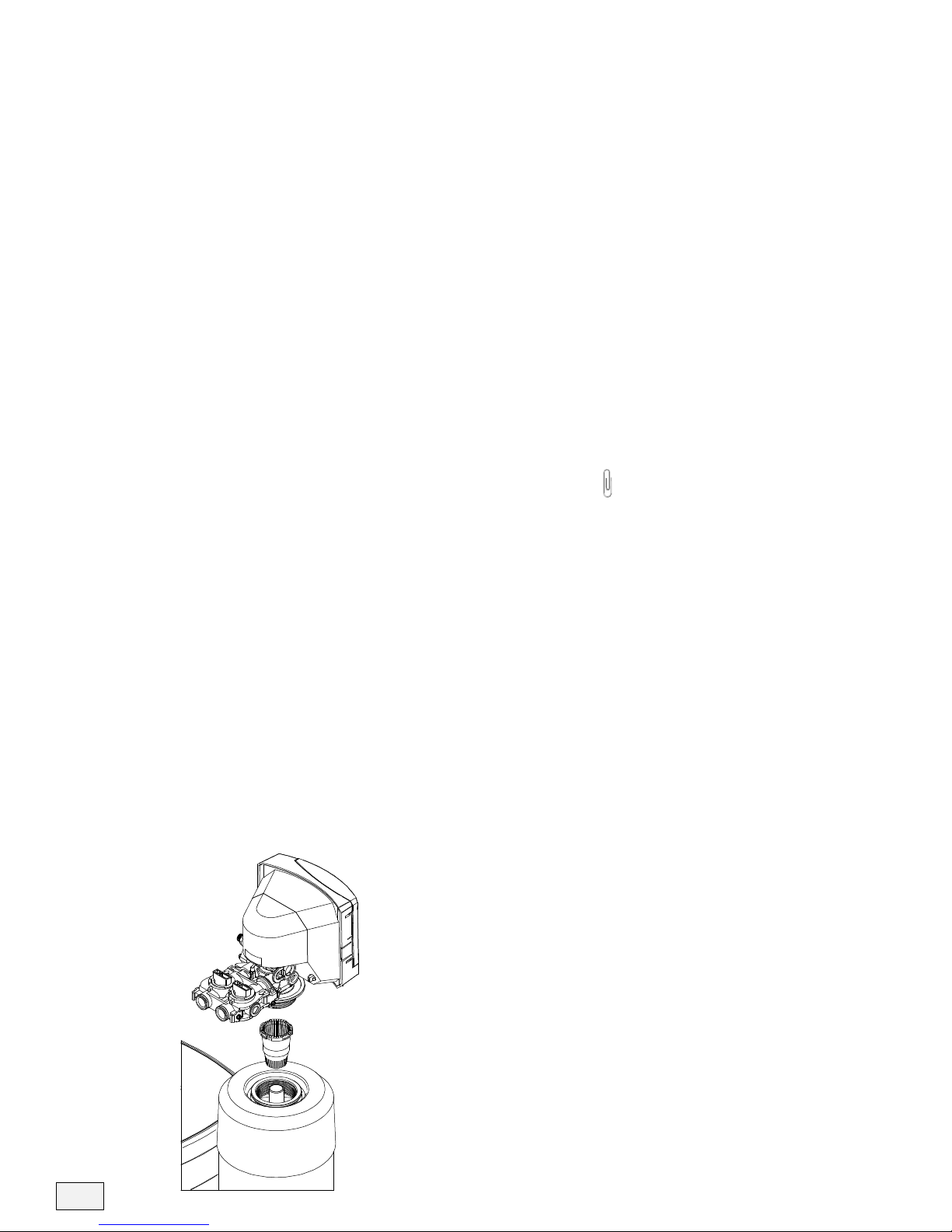
Adding Salt to your Brine Tank
1) ill the Salt Tank with Block Salt, bag Salt (Pellet) or
Potassium Chloride. or maximum salt capacity of the
brine tank, see table on page 11 for the maximum setting
salt levels.
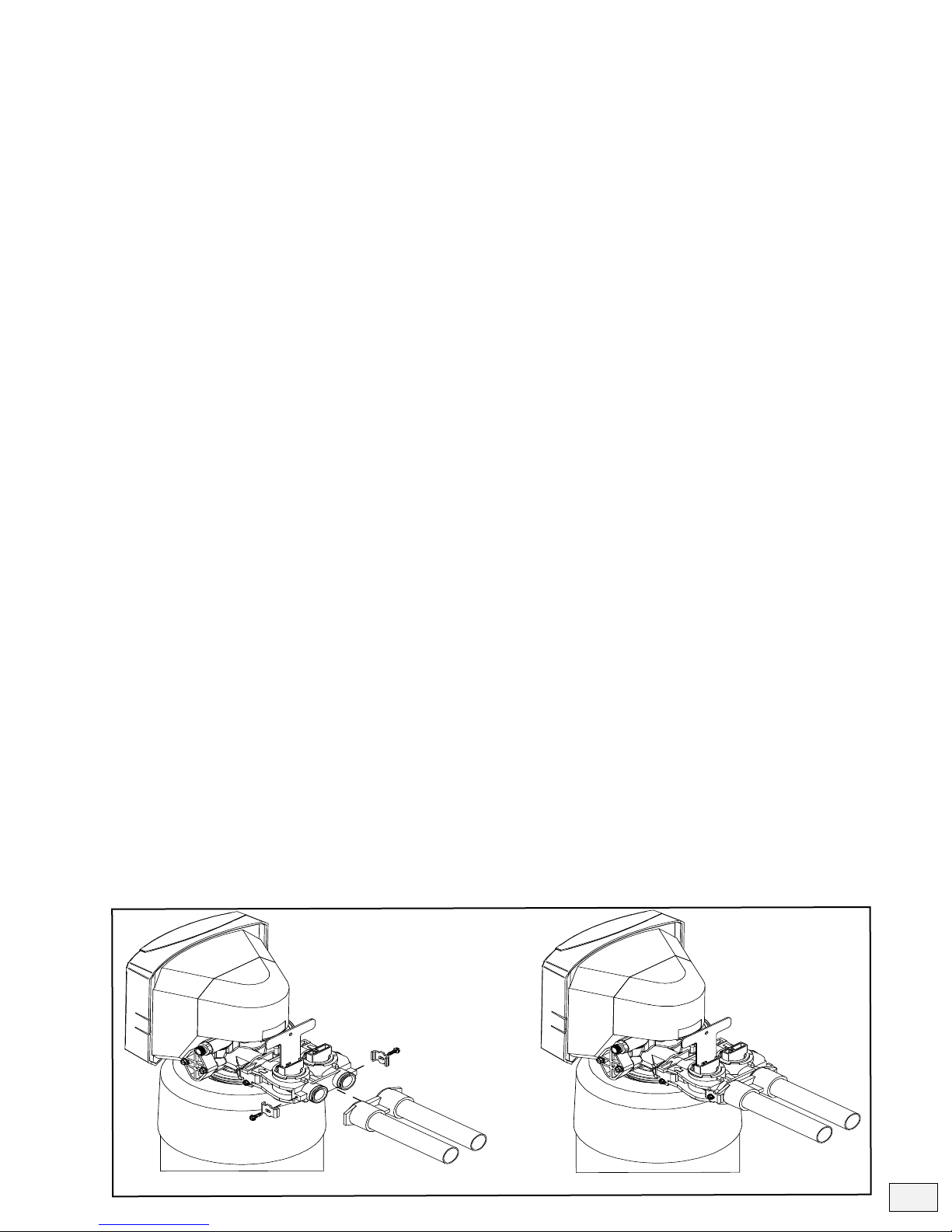
• Bag Salt and Potassium Chloride generally come in 40 lbs.
Pellet orm Bags. ill tank with pellets by empting contents
right into center of brine tank.
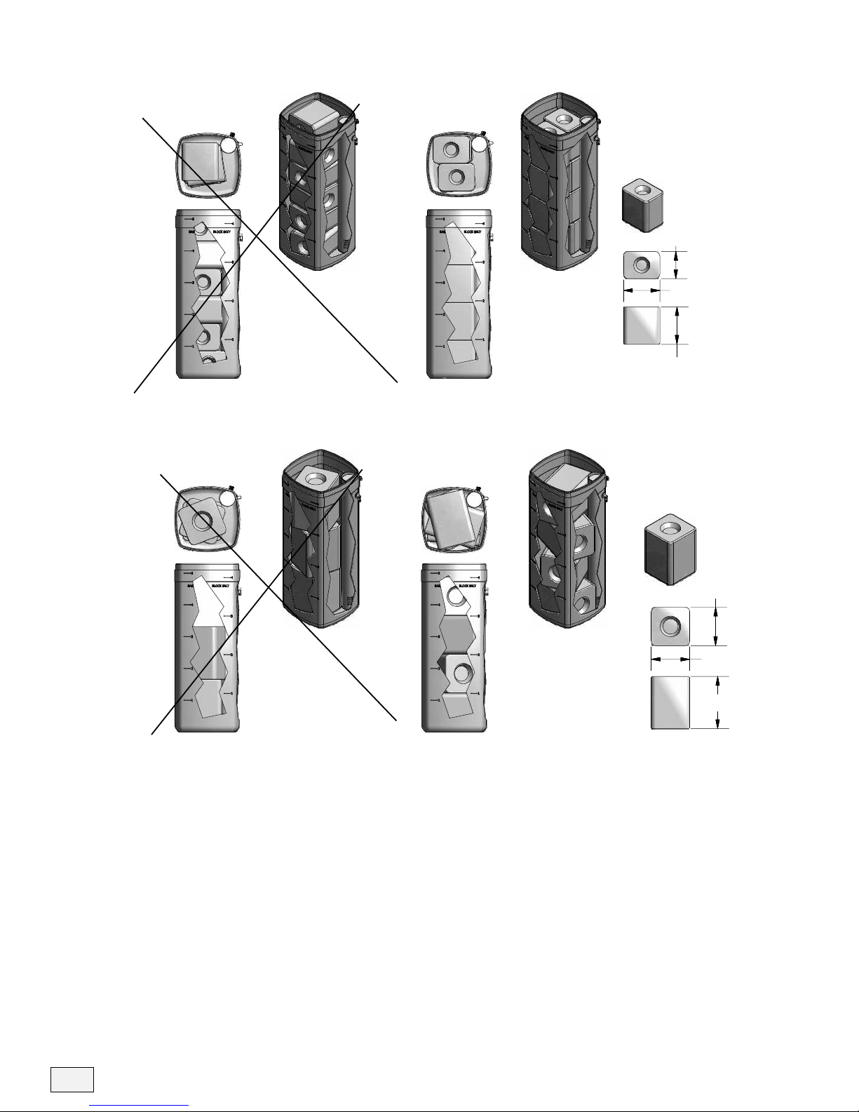
• Block Salt comes in 25 lbs. blocks or 50 lbs. blocks. See Block
Stacking igures on page 14 for correct and incorrect stacking
of block salt.
2) On the EC5, press any button from the home screen to enter
the Main Menu, then select >SALT LEVEL, Press Enter or
Right Arrow button. Using the Up and Down Arrows, set the
Salt Level to the level of salt that is filled in the brine tank. You
can reference the weight of salt you entered for more precise
entering of amount of salt used. Level of 1.0 is equal to 50 lbs.
22kg] of salt.
3) Press Enter Button to save new salt level and exit salt level
screen. Press the Left Arrow button to exit the Main Menu and
return to the Home Screen.
Note: Exiting Salt Level screen with the Left Arrow button will
NOT save new salt settings.
9
!
Important Note: It is important to main-
tain at least 15 lbs. to 30 lbs. of salt in
your brine tank to correctly regenerate
your System and to continue to enjoy soft
water. LOW SALT ALERTS will activate
for salt levels under 30 lbs.
!
Recommendations: If choosing to use
both Block and ellet form of salt when
filling the brine tank, we recommend
you maintain your settings on ellet
Form. We do not recommend this
method of filling your brine tank for
system sizes of EC5 150 and higher. The
total volume of salt in the full brine tank
will not allow enough room for water to
make the appropriate amount of brine
solution to regenerate the system fully.
!
Important Note: Salt for your water
conditioner can be readily purchased in
either bag or block form. Bagged salt
(sodium chloride) may be described on
the packaging as pellet, flake, crystal, or
solar salt. Any of these are fine, with the
most important point being that the salt
is clean, high purity, or labeled specically
as suitable for water softeners. Salt used
for melting ice, such as rock salt, is
typically high in impurities and should not
be used, since dirt can clog the brine
system. Very fine, granulated salt is also
not recommended.The use of granulated
salt may cause service problems.
Salt in block form should also be labeled
as high purity, solar or suitable for water
softeners. Blocks sold as cattle licks
should not be used, since these may be
high in impurities.
You can also use potassium chloride
instead of sodium chloride. otassium
chloride is usually available only in bags
and sold specifically for this purpose.

6. Sanitize the Conditioner
• Mix a 3/4 cup of common (unscented) 5.25% household bleach
with 1 quart of water. Pour this solution into the brine well.
• Initiate a manual regeneration. The solution will be drawn into the
conditioner during the regeneration process.
• After the system has completed a manual regeneration, the condi-
tioner will be sanitized and ready for use.
7. System Selectable Setting, Customer Menu,
Service Menu and Hidden Keys
•See page 11-16 for System selectable settings, Customer menu,
Service menu and Hidden key.
10
STACKIN G BLOCK SALT - 25 lbs B LOCK S
INCORRECT STACKING CORRECT STACKING
Incorrect Stacking Using
- 25 lb Salt Blocks
Standard Block Dims
- 8 x 6 x 8.5
Total Blocks Possible
- 6 =150 lbs of Salt
Level - 4.0 level
- equal to 200 lbs (Not Correct)
Correct Stacking Using
- 25 lb Salt Blocks
Standard Block Dims
- 8 x 6 x 8.5
Total Blocks Possible
- 8 =200 lbs of Salt
Level - 4.0 level
- equal to 200 lbs (Correct)
6"
8.5"
8"
Correct Stacking Using
- 50 lb Salt Blocks
Standard Block Dims
- 8.5 x 8.5 x 11.5
Total Blocks Possible
- 4 =200 lbs of Salt
Level - 4.0 level
- equal to 200 lbs (Correct)
Incorrect Stacking Using
- 50 lb Salt Blocks
Standard Block Dims
- 8.5 x 8.5 x 11.5
Total Blocks Possible
- 3 =150 lbs of Salt
Level - 4.0 level
- equal to 200 lbs (Not Correct)
INCORRECT STACKING CORRECT STACKING
STACKIN G BLOCK SALT - 50 lbs B LOCK S
11.5"
8.5"
8.5"

11
SYSTEM SELECTABLE SETTINGS
EC5 SYSTEM MODEL SETTINGS & DEFAULTS
Capacity Info
# Model
Unit Size
(Name)
MEDIA TYPES
Selectable
Actual RESIN
(Cu.ft)
Injector Size
Backwash Flow
Control
Refill Flow Control
Max Salt Level
BAG (DEFAULT)
Max Salt Level Block
Minum Salting
Dose (Lbs)
Maximum
Salting Dose
(Lbs)
130 V, CV, T, CT 0.30 #00 1.5 0.25 2.0 1.0 0.90 4.50
230SS V, CV, T, CT 0.30 #00 1.5 0.25 2.0 2.0 0.90 4.50
350 V, CV, T, CT 0.50 #00 1.5 0.25 5.0 4.0 1.50 7.50
460S V, CV, T, CT 0.60 #00 2.0 0.25 5.0 4.0 1.80 9.00
560SS V, CV, T, CT 0.60 #00 2.0 0.25 2.0 2.0 1.80 9.00
Default 675 V, CV, T, CT 0.75 #00 1.5 0.25 5.0 4.0 2.25 11.25
7100 V, CV, T, CT 1.00 #00 2.0 0.25 5.0 4.0 2.50 15.00
8100S V, CV, T, CT 1.00 #00 2.0 0.25 5.0 4.0 2.50 15.00
9150 V, CV, T, CT 1.50 #00 2.0 0.25 5.0 4.0 3.75 22.50
10 250 V, CV, T, CT 2.50 #0 3.0 0.50 10.0 10.0 6.25 37.50
11 400 V, CV, T, CT 4.00 #0 4.0 0.50 10.0 10.0 10.00 60.00
130SS- V, CV, T, CT 0.30 #00 1.5 0.25 2.0 2.0 0.90 4.50
260SS- V, CV, T, CT 0.60 #00 2.0 0.25 2.0 2.0 1.80 9.00
Default 360 V, CV, T, CT 0.60 #00 2.0 0.25 5.0 4.0 1.80 9.00
4100 V, CV, T, CT 1.00 #00 2.0 0.25 5.0 4.0 2.50 15.00
EC5 FILTER LINK MODEL SETTINGS & DEFAULTS
Additional System Settings
# Model
Unit Size
(Name)
MEDIA TYPES
Selectable
Actual RESIN
(Cu.ft)
Drinking Water
1EC5-FLT 50 H 0.50 None
Default 75 H 0.75 Ultrefiner Time: 6 to 84 months
100 H, A, AS 1.00 Hydrefiner
150 H, A, AS 1.50
Other
250 H, A, AS 2.50 House FILTER
None
Carbon Time: 6 to 84 months
Neutralizer Volume: 10K to 990K GALS
Sediment
Other
System 1
None
Clean Start Time: 6 to 84 months
AirMaster
UV
Ultra Filter
Other
System 2
None
Clean Start Time: 6 to 84 months
AirMaster
UV
Ultra Filter
Other
Types:
Types:
Types:
Types:
Service Intervals
Service Intervals
Service Intervals
Service Intervals
Salt Lbs Used
EC5-Cab
Max Setting Salt Levels
EC5
Model Type _ [EC5-75-CV}
Default Settings

12
MAIN MENU
>SALT LEVEL
>SYSTEM INFORMATION
>START REGENERATION
>CONFIGURE SETTING
>WI-FI SETTINGS
>FILTER LINK**
SYSTEM INFORMATION
>SYSTEM ALERTS
>ALARM HISTORY
>SYSTEM SETTINGS
>SYSTEM STATS
>ADDITIONAL SYSTEMS
>DEALER INFO
START REGNERATION
>Regenerate Now?
Start Regen Later?
Off / On – Time?
CONFIGURE SETTINGS
SET REGEN TIME:
02:00 AM
>SALT SETTINGS
>VACATION MODE
>TIME/DATE SET
WI-FI SETTINGS
Wi-Fi On/Off?
ON / Off
Mobile App Connect?
NO/YES
Registration Status
None/Pending/OK
Network Status
000.000.0.000
FILTER LINK **
Filter Model
Model – Size - Type
Filter Install Date
00/00/0000
Filter Last Regen
00/00/0000
Filter Regen Now?
Confirm: No/Yes
Filter Regen Time:
00:00 PM
Filter Days Set
2-30 Days
Press Any
Button
Turns on
Back Light
SALT LEVEL
SALT LEVEL: 5.0
SALT TYPE:
SODIUM
PELLET
250
lbs
Press Any
Button
MAIN CUSTOMER MENU
EC5 FLOW CHART;
CUSTOMER MENU
Program RS VER - 1.2 – 1.4
Adjust Salt Level using the
Up & Down Arrow Buttons.
Press ENTER TO SAVE &
LEFT Arrow TO EXIT
WITHOUT Saving.
** Filter Link Menu
Not Displayed when
Filter Link is Turned
Off in Service Menu /
Configure Settings
System Information
does not have any
adjustable settings via
the customer menu
Enter Main
Menu
EC5 Home Screen
Regen Later – set time
for EC5 to initiate a
Regen at later time.
Regen Time – set time
for EC5 to Regen.
Regen Process starts 2
Hours Before scheduled
time with Cycles 1 & 2
Wi-Fi On/Off – Turns
Wireless reporting on or
off. On is default even if
not connected.
Mobile App Connect –
Turns on direct connect
mode for users to
connect EC5 to Wireless
network via REMIND
App..
Filter Regen Now – will
initiate an immediate
regen of the filter.
Filter Days Set – sets
the days between filter
regenerations.
Filter Regen Time –
setting is not adjustable.
The start time is = 2:05
Hours before Regen
time + Total Filter Regen
Cycle Time.
FLOW CHART CUSTOMER MENU

13
CONFIRM REGEN NOW?
YES / NO
DATE TIME:
ALERT Description
List of last 4 Alerts
DATE TIME:
ALARM Description
List of last 4 Alarms
SYSTEM SETTINGS
Model
Model – Size – Resin Type
System Serial #
1121113
Installation Date
00/00/0000
Water Hardness
00 grains / gallon
Water Iron Level
0.0 ppm
SYSTEM STATS
CURRENT WATER FLOW
0.0 GPM
AVG WATER USE
000 Gallon/Day
TOTAL WATER 28 DAYS
00000 Gallons
TOTAL WATER USED
0000000 Gallons
LAST REGEN DATE
00/00/00
GAL SINCE LAST REGEN
00 Gallons
AVG WEEKLY SALT
00 lbs
REGENS LAST 28 DAYS
0
ADDITIONAL SYSTEMS
Drinking Water
None / TYPE (install Date)
House Filter
None/Type (install Date)
System 1
None/Type (install Date)
System 2
None/Type (install Date)
DEALER INFO
DEALER
RainSoft (or Custom)
PHONE
800-724-6763 (or Custom)
Email Address
Remind@rainsoft.com (or
Custom)
SALT SETTINGS
SET LOW SALT ALERT
OFF / ON
SALT AUDIBLE TIME
05:00 PM
SALT TYPE
Sodium / Potassium
SALT FORM
Pellet / Block
VACATION MODE
Vacation Mode
OFF /ON
Set Total Days Away
2 - 180
SET TIME & DATE
Set Time
00:00 AM
Set Day of Week
Monday
Set Date
00/00/0000
Daylight Savings
On / Off
Set Time Zone
UTC #
SYSTEM INFORMATION
START REGENERATION
Salt Alert will sound
Audible Alerts at set
time when Low Salt
Status is active.
Regen Now will exit to
Home Screen. Count
down from 10 will begin.
Press Any Button to
Cancel Regen.
Salt Type – Sodium or
Potassium – Customers
can change Salt types.
Salt Form – Pellet or
Block – This affects the
Salt Level Max Height
On most units.
Vacation Mode –
Turning On VM will
cause any Days
override settings to not
Regen until out of VM.
Conditioner and Filter
Link.
Time & Date Settings –
Maintain Time Settings
to insure regens take
place on correct
schedule.
TIME ZONE – Correct
UTC Time setting is
important for Wi-Fi
Settings to ensure info is
transmitted correctly.

14
SERVICE MENU
>Configure System
>System Info
>System Testing
>Dealer Info
>Wi-Fi Settings
Press And Hold UP
Button 7 to 10 seconds
Press UP
Button 2x
Enter Authorize Code:
CONFIGURE SYSTEM
>System Setup
>System Overrides
>Filter Link
>Auxiliary Settings
>Additional Systems
SYSTEM INFO
>RegenInfo
>Alert History
Clear Alert?
No/Yes
>Alarm History
Clear Alarm?
No/Yes
>Water Stats
>Service History
Add New Service Tag
Codes: [1][2][3][4][5]
>Board Info
SYSTEM TESTING
>Run Electrical Test
Line Power Level
## Volts
Audio Test
Off / On
Aux Control 1
Off/ On
Aux Control 2
Off / On
>Cycle Motor Test
>Cycle 2nd Motor Test
>Motor Jog
DEALER INFO
DEALER
RainSoft
PHONE
800-724-6763
Email Address
Remind@rainsoft.com
WI-FI SETTINGS
>SCAN NETWORKS
Enable Service App
NO/YES
Network Status
000.000.0.000AVAILABLE NETWORKS
List of wireless networks /
SSID in ra nge of EC5
control.
(U/D) Jog by: 10
(R/L ) MTR1 Targ et: 650
ADC V ALUE: 645
{Press Enter B utton to Exit}
Mot or 1 Test
Curren t Position: #
Cycle Count: 000
[Press Left Bu tton to Exit]
Mot or 2 Test
Curren t Position: #
Cycle Count: 000
[Press Left Bu tton to Exit]
Electrical Test:
Follow Instructions
(Press if Test Fai ls Press
Down to Exit)
SERVICE MENU
Service Tags:
Add as many Tags per service
as required. Number definitions
are:
1. Scheduled System PM
2. System Repair Required
3. Filter Change
4. Change in EC5 Settings
5. New Equipment Install
SYSTEM TESTING
EC5 Home Screen
DEALER INFO
The Phone Number can be
edited in the EC5 by the EC5
Control.
Dealer Name / Email address
requires RS SERVICE App.
EC5 FLOW CHART;
SERVICE MENU
Program RS VER - 1.2 – 1.4
FLOW CHART SERVICE MENU

15
SYSTEM SETUP
Units
English / Met ric
Model
EC5 / EC5-CAB
Unit Size
{Size of S ystem}
Media Type
V, CV, T, CT
Hardne ss
01-99 grains/ gallon
Iron
0.0 ppm
Time o f Regen
02:00 AM
Start Capa city
30%-80%
Water P ressure
20 to 1 00 PSI
System Serial #
1121113
Installa tion Date
00/00/000 0
Tota l Capacity
### Gallons
Water to Start Regen
## Gallons
SYSTEM OVE RRIDES
90% Exha usted Regn
Immediate / Delayed
Injector Size
00 / 0 / 1
Backwa sh Control
Size s ( 1 thru 10)
Max Sa lt Override
Off (or set max level)
Regen Days Overrid e
Off / 1 thru 30 Da ys
>Mod Cycle Times
LED output O verride
OFF / ON
MOD CYCLE TIMES
C1 – Brine Fill
Add 0 to 15 Minutes
C2 – Brin e Make up
120 – 60 Minutes
C3 – Backwash
1 – 30 Minutes
C4 – Brine/S-Rinse
Add 0 to 20 Minutes
C5 – F-Rinse
Add 0 to 10 Minutes
FILTER LINK
Filter Mode l
Off / EC5-FLT
Filter S ize
{Size of Filter System}
Filter Type
H, A,AS, Y, Y Z, R,
Filter Install Date
00/00/000 0
Filter Cycle 3 Time
1 to 40 Minutes
Filter Cycle 4 Time
0 to 60 Minutes
Filter Cycle 5 Time
1 to 40 Minutes
Filter Rege n Time
{Calculated Start time}
Filter Days Set
1 to 30 Days
Service Reminders
Off / Time / Volume
Service Intervals
None/Months/Gallons
Time/Volume Re mai n
0 /# Months/# Ga llons
Service Reminder
Reset: No / Y es
AUX ILIARY SETTINGS
Acti vate Aux 1
OFF / 1 / 2 / 3
Acti vate Aux 2
OFF / 1 / 2 / 3
<Drinking Wat er >
Type:
None/Ultrefiner/Hydrefiner/Other
Install Date:
00/00/0000
Service Interval
Off /Time: 6 to 8 4 Months
Service Remaining
# Months RES ET: No / Yes
< House Filter >
Typ e:
None /Carbon/Neutralizer/Sediment/Ot her
Install Date:
00/00/000 0
Service Interval
Off /Time/Vol: 6 to 8 4 Months 10 K to 99 0K
Gals
Service Remaining
# Months / GALS RESE T: No / Ye s
< System 1 >
Typ e:
None /Clean Start/ AirMaster/ UV / Ultra
filte r / Other
Install Date:
00/00/0000
Service Interval
Off /Time: 6 to 8 4 Months
Service Remaining
# Months RESET: No / Yes
< System 2
Typ e:
None /Clean Start/ AirMaster/ UV / Ultra
filte r / Other
Install Date:
00/00/000 0
Service Interval
Off /Time: 6 to 8 4 Mont hs
Service Remaining
# Months RES ET: No / Yes
REGEN INFO
>Last Re gen In fo
>Last 5 Reg ens
Regens last 14 Days
#
Regen s last 28 Days
#
Tota l Regenerations
#
Avg Weekly Salt Used
# lbs
Last Regen Info L isted:
Date / Time
Tota l G allons before
regen
Salt lbs Calculated
Cycle 1 thr u 5 Times
Last 5 Regen Info
Listed:
Date / Time of La st 5
WATER S TATS
Total Capa city
## Gallons
Water To Start Regen
## Gallons
Water A vailable
# Gallons
Avg Water per Day
# Gallons/Day
Water L ast 28 Da ys
## Gallons
Total Water Used
### Gallons
Service History
Date / Time
Service Tags: #, #
List of last 4 Service Tags
BOARD INFO:
Program Revision
RS-EC5-VER-##
EEPROM Revision
EEPROM -EC5-VER- ##
DATE TIME:
ALERT Description
List of last 4 Alerts
DATE TIME:
ALARM De scription
List of last 4 Alarms
AUX S ettings
- Setting (1) Aux Output Signal on
during; REGE N Cycles [3],[4],[5]
Both EC5 and FILTER L INK
- Setting (2) Aux Output Signal on
during: REGE N Cycles [4] EC5
- Setting (3) Aux Output S ignal on
during: REGEN Cycles [3],[4],[5]
FILTER LINK Only
CONFIGURE SYSTEM MENU
SYSTEM INFO MENU
Additional Systems Menu
USE LEFT & RIGHT
ARROW BUTTONS
TO NAVIGATE
BETWEEN
ADDITIONAL
SYSTEMS MENUS

16
SERVICE MENU
>Configure System
>System Info
>System Testing
>Dealer Info
>Wi-Fi Settings
Press UP
ARROW 2x
Enter Authorize Code:
<Drinking Wat er >
Typ e:
None/Ultrefiner/Hydrefiner/Othe r
Install Date:
00/00/0000
Service Interval
Off /Time: 6 to 8 4 Mont hs
Service Remaining
# Months RESET: No / Ye s
< House Filter >
Type:
None /Carbon/Neutralizer/Sediment/Other
Install Date:
00/00/0000
Service Interval
Off /Time/Vol: 6 to 84 Months 10 K to 990K
Gals
Service Remaining
# Months / GALS RESE T: No / Ye s
< System 1 >
Typ e:
None /Clean Start/ AirMaster/ UV / Ultra
filter / Other
Install Date:
00/00/0000
Service Interval
Off /Time: 6 to 8 4 Mont hs
Service Remaining
# Months RESET: No / Yes
< System 2
Type:
None /Clean Start/ AirMaster/ UV / Ultra
filte r / Other
Install Date:
00/00/0000
Service Interval
Off /Time: 6 to 8 4 Mont hs
Service Remaining
# Months RESET: No / Yes
USE LEFT & RIGHT ARROW BUTTONS
TO NAVIGATE BETWEEN ADDITIONAL
SYSTEMS MENUS
EC5 Home Screen
Additional Systems
Press & Hold LEFT
ARROW 5to 7
Seconds – Access
Additional Systems
Screens.
Press & Hold UP
ARROW 5 to 7
Seconds –
SERVICE MENU.
CLEAR ALARMS &
ALERT MESSAGES
Press & Hold DOWN
ARROW 5 to 7
Seconds – to clear all
active alarms and
alerts
PROGRESS THRU EACH
REGENERATION STEP,
ONLY DURING REGEN.
Press & Hold RIGHT
ARROW 5 Seconds –
During Regen to
Progress thru Cycles.
EC5 SERVICE MENU Screen
EC5 FLOW CHART;
EC5 HIDDEN KEYS
Program RS VER - 1.2 – 1.4
FLOW CHART HIDDEN KEYS

Incoming Water Conditions
(Hardness Settings/ Iron
Settings)
Hardness setting is adjustable to match incoming water hardness in
grains/gallon. Range is 2 – 200 grains per gallon(gpg), in increments
of 1, with a default of 10.
Iron level is adjustable to match incoming iron level in parts per
million (ppm). Range is 0 – 3 parts per million (ppm), inincrements
of 0.5, with a default of 0.
A combined hardness setting is calculated as follows:
•Combined hardness setting = hardness setting (gpg) +
(iron level (ppm) x 6 gpg/ppm)
•Combined hardness setting is never displayed, but used in
capacity calculations.
•Iron Level of greater than or equal to 0.5 ppm will change
the START CAPACITY to change to 50% and only allow
for adjustment from 50% to 80%.
Example: Hardness set at 10 Grains, Iron Set at 1.5 ppm = Capacity
calculations use 19 Grains / 50% Start Capacity before Regen can be
triggered.
Metric Conversion Factors
(Units) Settings
•Gal / Grain / AM:PM (Imperial Settings)
•L / PPM / 24:00 (Metric)
• L / TH / 24:00 (Metric - rench Degrees)
1 gallon = 3.785 liters (l)
1 grain/gallon = 17.1 ppm = 1.71 th
1 lb. = .454 kilograms (kg)
Metric - Clock is displayed in 24-hour mode without AM or PM
Metric - Date is displayed as DD/MM/YY instead of MM/DD/YY.
In general, all calculations are based on Imperial units, then
converted for display purposes to metric when metric units are
selected.
Hardness settings in Metric, increase is every 17.1 ppm per 1 grain
(Imperial) and in Metric rench Degree, 1.71 th per 1 grain
(Imperial)
17

18
Troubleshooting Guide
4. Loss of resin to the drain
during backwash
3. Loss of resin to the
plumbing
2. System is using large
amounts of salt
1. Hard water/ Hard water
bleed-through
Symptom Cause Solution
1. The system is not regenerating often enough. 1. System is running out of capacity because the
hardness or capacity setting is incorrect. Test
the raw water, verify model, and reset if
necessary.
2. The check ball behind the injector is not seating. 2. Replace the check ball seat assembly.
3. The system is out of salt. 3. Add salt to the brine tank.
4. The system has lost power. 4. Check the power connection to the system.
5. The bypass valve is open or partially open. 5. Close the bypass valve completely.
6. The plumbing is not properly connected to the
system.
6. Replumb the system.
7. Salt is bridged in the brine tank. 7. Bag salt can sometimes form a bridge, which
will not allow the water to dissolve the salt.
Pour hot water along the sides of the brine tank
and use a tool to break the bridge.
8. The system will not draw brine. 8. See Symptom 6.
9. Worn internal seals. 9. See Symptom 6.
10. Bypass seals have failed. 10. Replace the bypass seals.
1. Soft water is being used to water the lawn. 1. Bypass the outside faucet(s) or show the
customer how the use the bypass valve while
watering the lawn.
2. The capacity or hardness setting is improperly set. 2. Verify that the settings are correct .
3. The brine refill rate is incorrect. 3. See Symptom 7.
1. The system is plumbed in backwards. 1. Replumb the system.
2. The riser pipe distributor is damaged. 2. Replace the riser pipe.
5. Valve out of
synchronization or does
not stop in the correct
position
1. Rotary position sensor. 1. Replace the motor sensor Assy.
2. Valve cam and brine cam are out of synchronization. 2. Realign cams.
3. Drive motor failed. 3. Replace the drive motor.
1. The backwash flow rate is too fast for the size of
the tank.
1. Make sure the system has the proper backwash
flow control (see below).
80tanks – 1.5 gpm backwash flow control
100tanks – 2.0 gpm backwash flow control
130tanks – 3.0 gpm backwash flow control
140tanks – 4.0 gpm backwash flow control
If the troubleshooting guide did not resolve the symptom, please contact Technical Support at 1-800-860-7638.

19
Troubleshooting Guide
11. Loss of water pressure
10. Salty water after
regeneration
9. Water is leaking at the
drain
Symptom
6. No brine draw, poor brine
draw, or loss of vacuum
7. Insufficient brine refill or
no brine refill
8. Excessive water in the
brine tank
Cause Solution
1. Low water pressure. 1. The water pressure must be above 20 psi.
4. Brine cam Lobe is worn or broken. 4. Replace the Brine cam.
2. Plugged injector or plugged injector screen.
If the injector is completely plugged, there will be
no flow to the drain. In most cases, the injector is
partially plugged and the flow is reduced. Normal
flow to the drain is about 1/2 the rate of backwash.
2. Inspect the injector and injector screen for
debris; clean or replace if necessary.
3. The internal seals are worn.
If the internal seals are worn, flow to the drain is
greater than normal. Normal flow to the drain is
about 1/2 the rate of backwash.
3. Inspect the internal seals; replace if necessary.
1. The brine refill flow control is plugged or restricted. 1. Inspect and clean the flow control and housing.
3. Low water pressure. 3. Increase the water pressure.
2. The brine refill flow control is not the correct size. 2. Replace with the correct size.
If the troubleshooting guide did not resolve the symptom, please contact Technical Support at 1-800-860-7638.
1. Debris is stuck in the refill stem. 1. Remove the brine line from the valve. If water
is coming out of the fitting, clean the brine
refill stem. Verify that the brine refill stem is
not depressed. If the stem is depressed, the
valve is not in the service position.
2. The system is not drawing brine. 2. See Symptom 6.
3. Air leak on the brine line connection. 3. Inspect the connections.
1. Water is leaking past the upper valve seals due to
worn seals or high water pressure.
1. Replace the internal seals or install a pressure
regulator.
2. The valve is not in the Service position. 2. Verify the position of the valve.
3. Drive cam is worn. 3. Replace the drive cam.
1. Low water pressure. 1. The water pressure must be above 20 psi.
2. Poor brine draw. 2. See Symptom 6.
3. The drain line is clogged or pinched. 3. Inspect the drain line.
4. Excessive water use during regeneration. 4. Instruct customer not to use water during
regeneration.
1. ouled resin due to iron/mineral accumulation. 1. Clean the valve and mineral bed with iron
cleaner or replace the resin.
2. The resin is broken-down. 2. Replace the resin.
4. Water pressure is set too high on the control. 4. Check incoming pressure and set control to
match.

20
Valve Exploded View
9
8
7
5
4
3
21
6
27 ABCD
22
23
24
10
25
30
31 AB
28
11
12
32
13
17
14
15
16
26 ABCDE
29
18
19
20 AB
21
Other manuals for EC5 Series
1
This manual suits for next models
1
Table of contents
Other Rain Soft Water Dispenser manuals
Popular Water Dispenser manuals by other brands

Elkay
Elkay EZSTLDWS 1G Series Installation & use manual

Judo
Judo QUICKSOFT-DUO Installation and operating instructions

NuvoH2O
NuvoH2O Manor Duo installation manual

Pentair
Pentair PCFE40P12 owner's manual

Haier
Haier WDLT165 installation manual

Whirlpool
Whirlpool Hot water dispenser Installation instructions and use and care guide