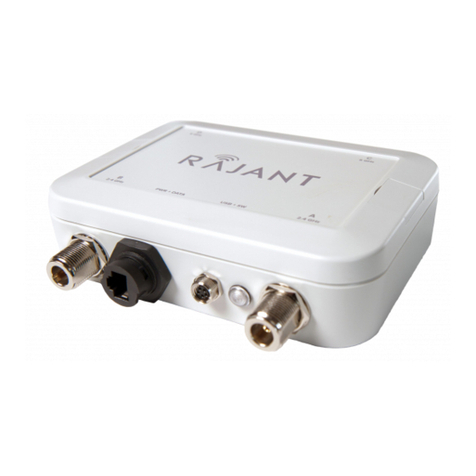
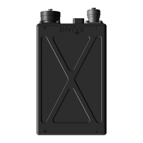
Rajant BreadCrumb ME3-09 User manual

BreadCrumb® ME3
ME3-09 / ME3-24
USER GUIDE
User Guide Version: 2.01
Software Version: 10.25
Date: August 31, 2011
Corporate Headquarters
Rajant Corporation
400 East King Street
Malvern, PA 19355
Tel: (484) 595-0233
Fax: (484) 595-0244
http://www.rajant.com
Document Part Number: 03-100116-001

ii
FCC and IC Statements
This equipment has been tested and found to comply with the limits for a Class A digital device,
pursuant to Part 15 of the FCC Rules. These limits are designed to provide reasonable protection
against harmful interference when the device is operated in a commercial environment. This device
generates, uses, and can radiate radio frequency energy and, if not installed and used in accordance
with this instruction manual, may cause harmful interference to radio communications. Operation of
this device in a residential area is likely to cause harmful interference in which case the user will be
required to correct the interference at their own expense.
This Class A digital apparatus complies with Canadian ICES-003 and RSS-210 rules.
Cet appareil numérique de la classe A est conforme à la norme NMB-003 et CNR-210 du Canada.
WARNING: To satisfy FCC RF exposure requirements a minimum safe distance of 20 cm must be
maintained between this device and all persons while the device is operating.
CAUTION: To reduce potential radio interference to other users, the antenna type and its gain
should be chosen so that the equivalent isotropically radiated power (EIRP) is not more than that
permitted for successful communication.
CAUTION: Changes or modifications not expressly approved by Rajant Corp. could void the user's
authority to operate the equipment.
Copyright Statement
You may use the software provided with the products only on personal computers owned by the
purchasing individual or entity, and may not use, load, or run any such software on any network or in
any type of service bureau, time-sharing operation, or non-purchasing individual or entity's
equipment.
BCAdmin and BCAPI are trademarks; Rajant, the Rajant logo, BreadCrumb, Instamesh, BC|
Commander, and Bring Your Network with You! are registered trademarks of Rajant Corp. in the
United States and certain other countries.
BreadCrumb
®
ME3 User Guide
Copyright © 2009–2011 Rajant Corp. All rights reserved.
ii

Rajant Corporation BreadCrumb
®
ME3 User Guide
03-100116-001 Version: 2.01
Table of Contents
FCC and IC Statements..................................................................................................ii
Copyright Statement.......................................................................................................ii
Preface....................................................................................................................................v
Purpose and Scope.............................................................................................................v
User Information..................................................................................................................v
Related Documentation.......................................................................................................v
1 Introduction to BreadCrumbs..........................................................................................1
1.1 What is a BreadCrumb?...............................................................................................1
1.2 Mobility through Meshing.............................................................................................2
1.2.1 Mesh – A Definition...............................................................................................2
1.2.2 BreadCrumb Mesh Connections..........................................................................2
2 Description of a BreadCrumb ME3..................................................................................5
2.1 Radio............................................................................................................................5
2.2 Enclosure.....................................................................................................................6
2.3 18-Pin Amphenol Connector........................................................................................7
2.3.1 Power....................................................................................................................7
2.3.2 Ethernet................................................................................................................8
2.3.3 USB.......................................................................................................................8
2.4 Antenna Connector......................................................................................................8
2.5 Status LED...................................................................................................................8
2.6 LED Configuration / Zeroize Keys and Restore Factory Defaults Switch...................9
2.6.1 LED Configuration..............................................................................................10
2.6.2 Zeroize Keys and Restore Factory Defaults.......................................................10
2.7 Internal Battery...........................................................................................................11
2.7.1 Protection Circuit................................................................................................12
2.7.2 Charging Circuit..................................................................................................12
2.7.3 Gas Gauge Circuit..............................................................................................12
2.7.4 Battery Monitoring...............................................................................................13
3 Using BC|Commander....................................................................................................15
4 Deploying the BreadCrumb Wireless Network............................................................17
4.1 Addressing.................................................................................................................17
4.1.1 BreadCrumb Device Addresses.........................................................................17
4.1.2 DHCP..................................................................................................................17
4.2 Channel Assignments................................................................................................17
4.3 Physical Placement and other Considerations..........................................................18
4.3.1 Line-of-Sight.......................................................................................................18
4.3.2 Distance..............................................................................................................18
iii

BreadCrumb
®
ME3 User Guide Rajant Corporation
Version: 2.01 03-100116-001
4.3.3 Weather..............................................................................................................19
4.3.4 Interference.........................................................................................................19
4.3.5 Placement of BCWN Components.....................................................................20
4.4 Deployment Guidelines and Methodology.................................................................20
4.4.1 Deployment Guidelines......................................................................................20
4.4.2 Deployment Methodology...................................................................................21
5 BreadCrumb ME3 Firmware Upgrade...........................................................................23
5.1 Over The Air Firmware Upgrade................................................................................23
5.2 USB Firmware Upgrade.............................................................................................23
6 Troubleshooting..............................................................................................................25
6.1 Sporadic Network Connectivity..................................................................................25
6.2 BreadCrumb Device Cannot Connect to BCWN.......................................................26
6.3 BreadCrumb Power and Start-Up Issues..................................................................26
Appendix A: Error and Warning Codes..........................................................................A-1
List of Figures
Figure 1: All BreadCrumbs use the same ESSID...................................................................3
Figure 2: ESSID of BreadCrumb C changes to "lonely.".........................................................3
Figure 3: BreadCrumb ME3 Enclosure Features...................................................................6
Figure 4: 18-Pin Amphenol Connector...................................................................................7
List of Tables
Table 1: 2.4 GHz Radio Channels and Frequencies..............................................................5
Table 2: 900 MHz Radio Channels and Frequencies............................................................6
Table 3: Status LED Color Codes..........................................................................................9
Table 4: Default and alternate display states of the Status LED..........................................10
Table 5: BreadCrumb ME3-24 battery load versus current consumption and run time......11
Table 6: Default Channel Assignments................................................................................18
Table 7: Sporadic Network Connectivity Issues...................................................................25
Table 8: BreadCrumb to BCWN Connectivity Issues...........................................................26
Table 9: BreadCrumb Power and Start-Up Issues...............................................................26
iv

N
ot
e
Rajant Corporation BreadCrumb
®
ME3 User Guide
03-100116-001 Version: 2.01
Preface
Purpose and Scope
This manual provides information and guidance to all personnel who are involved with and use
Rajant Corporation’s BreadCrumb ME3.
This manual begins with an introduction to the BreadCrumb Wireless Network (BCWN). It then
characterizes the features of the BreadCrumb ME3. Finally, it describes common deployment
scenarios and provides concise step-by-step instructions for each scenario.
Throughout this document, unless otherwise stated, the terms ME3 and
BreadCrumb are used to refer to Rajant BreadCrumb ME3.
User Information
The user of this manual is encouraged to submit comments and recommended changes to improve
version number of the manual you are using and please provide the page numbers related to your
comments wherever possible
Related Documentation
For additional information, refer to these documents:
●
Rajant BC|Commander® User Guide: This document contains information on the
BC|Commander management application, which is used to configure BreadCrumbs before or
during a deployment. This now includes a BreadCrumb VLAN Guide.
●
BreadCrumb® Video Guide
●
Rajant Troubleshooting Range User Guide
●
RF Component Installation and Verification in BreadCrumb® Networks
v


Rajant Corporation BreadCrumb
®
ME3 User Guide
03-100116-001 Version: 2.01
1 Introduction to BreadCrumbs
Rajant Corporation's (http://www.rajant.com) BreadCrumbs utilize the 802.11 wireless networking
standards to form a wireless mesh network. The network is mobile, self-integrating, self-meshing,
self-healing, and secure. The focus is on flexibility, adaptability, and simplicity.
The BreadCrumb Wireless Network (BCWN) is intended for rapid deployment of a broadband
wireless network into a situation or “hot zone.” The network can be deployed as a stand-alone
wireless network, or bridged to another network (such as the Internet) utilizing available reach-back
communication links (such as a DSL, cable, or satellite modem).
BreadCrumbs provide high bandwidth for applications to stream video, audio as well as data over
large distances. The network traffic can be secured by using different security features offered by
the BCWN. This makes the network optimal for tactical deployments as well as emergency
response situations since it offers robustness, stability and ease of setup in mission critical activities.
1.1 What is a BreadCrumb?
ABreadCrumb is an IEEE 802.11 (Wi-Fi) and Ethernet compatible networking device which has the
capacity to connect to other BreadCrumbs or networking devices to form a BreadCrumb network. A
BreadCrumb is specifically designed for the following scenarios:
Temporary Wireless Networks
Networks that must be established quickly and with minimal effort for short-term use (e.g., a
network established to provide First Responder support at the site of a disaster).
Mobile Wireless Networks
Networks in which the network infrastructure itself is mobile, in addition to client devices (e.g., a
convoy viewing a video stream from a UAV).
Wireless Network Extension
Networks in which a wireless network must be quickly extended around or through obstacles that
block wireless communications (e.g., urban canyon networks, tunnels/caves, etc.)
Wired Network Extension
Networks in which two or more wired LANs at different locations must be connected wirelessly
(e.g., to securely connect combat service support computers with logistics bases)
Any Combination of the Above
Most BreadCrumb deployments include elements from more than one of the above scenarios.
In many cases, BreadCrumbs will perform all of these tasks as shipped with no configuration
necessary at all, providing an instant TAN (Tactical Area Network). Moreover, because
BreadCrumbs use industry-standard 802.11 communications, client devices such as laptops or
handheld computers require no special hardware, software, or configuration to access a BCWN.
1

BreadCrumb
®
ME3 User Guide Rajant Corporation
Version: 2.01 03-100116-001
1.2 Mobility through Meshing
The key component to a BCWN is a technique known as Meshing. While this is generally handled
automatically by BreadCrumbs, complex deployment scenarios require a basic understanding of how
BreadCrumbs establish and maintain a mesh.
1.2.1 Mesh – A Definition
Amesh is a collection of network devices (in our case, BreadCrumbs), each of which is linked to one
or more other BreadCrumbs. Data can move between BreadCrumbs via these links, possibly passing
through several intermediate BreadCrumbs before arriving at its final destination.
The intelligence of a BCWN is in how it adapts rapidly to the creation or destruction of the links in
the mesh as devices are moved, switched OFF or ON, blocked by obstructions, interfered with by
other devices, or otherwise affected. This adaptation takes place automatically and immediately as
needed.
Note
Although all BreadCrumbs can be access points, most access points do not provide
mesh capability. Traditional access points simply allow wireless devices within
range to connect to a wired network; they do not extend range through other access
points.
1.2.2 BreadCrumb Mesh Connections
In order for two BreadCrumbs to establish a mesh link to each other, they must be set to the same
radio channel, and the same ESSID, and have the same InstaMesh key settings. An ESSID is
essentially a name for a wireless network. By default, BreadCrumbs use the ESSID "breadcrumb54-
v10” if programmed with version 10 firmware. InstaMesh key settings include the Network
Authentication Key (NAK) and the Network Encryption Key (NEK).
Assuming that the security settings are the same, the following examples illustrate how the use of
channels and ESSIDs can establish or break mesh links:
2

CHANNEL
8
CHANNEL 8
Rajant Corporation BreadCrumb
®
ME3 User Guide
03-100116-001 Version: 2.01
Example 1:
Suppose you have three BreadCrumbs, called A, B, and C. Each has two radios. BreadCrumb A’s
radios are on channels 1 and 8, B’s are on 8 and 11, and C’s are on 1 and 11. All three BreadCrumbs
are using the default ESSID of "breadcrumb54-v10." Assuming that all three BreadCrumbs are
within radio range of one another, the network will be connected, as shown below:
BREADCRUMB
A
RADIO 1 RADIO 2
CHANNEL1
BREADCRUMB C
RADIO 1 RADIO 2
RADIO 1 RADIO 2
BREADCRUMB B
Example 2: Figure 1: All BreadCrumbs use the same ESSID.
Now suppose that you change the ESSID of BreadCrumb C to "lonely". The network will adjust to
this change, resulting in the following configuration:
BREADCRUMB A
RADIO 1 RADIO 2
BREADCRUMB C
RADIO 1 RADIO 2
RADIO 1 RADIO 2
BREADCRUMB B
Figure 2: ESSID of BreadCrumb C changes to "lonely."
Note that BreadCrumb C can no longer communicate with A or B, and vice versa.
3


Rajant Corporation BreadCrumb
®
ME3 User Guide
03-100116-001 Version: 2.01
2 Description of a BreadCrumb ME3
The BreadCrumb ME3 is a portable, battery operated, wireless device deployable in almost any
environment. It is light in weight, offers one external antenna and a rechargeable battery, and is
designed to be completely mobile as worn by an individual.
2.1 Radio
The BreadCrumb ME3 comprises one 802.11g radio. The ME3-09 operates in the 900 MHz
frequency band. The ME3-24 operates in the 2.4 GHz frequency band. The radio supports the
channels and frequencies listed in Tables 1, and 2 in the United States and Canada.
Note
Not all channels are allowed for use everywhere around the world. Check with the
corresponding wireless spectrum regulatory body to determine the subset of
channels authorized for use in your country.
The radios sold in Brazil only support the center frequency in 922 MHz .
Table 1: 2.4 GHz Radio Channels and Frequencies.
Channel Number
Center Frequency (MHz)
1
2412
2
2417
3
2422
4
2427
5
2432
6
2437
7
2442
8
2447
9
2452
10
2457
11
2462
The default channel for a 2.4 GHz BreadCrumb radio is 11 (2462 MHz).
5

BreadCrumb
®
ME3 User Guide Rajant Corporation
Version: 2.01 03-100116-001
Table 2: 900 MHz Radio Channels and Frequencies.
Channel Number
Center Frequency (MHz)
5
912
6
917
The default channel for a 900 MHz BreadCrumb radio is 5 (912 MHz).
2.2 Enclosure
The ME3 enclosure has been designed to operate in extreme conditions with protection against
ingress of dust as well as protection against immersion in water. The enclosure dimensions are 176
mm x 95 mm x 48 mm (6.94” x 3.75” x 1.88”).
The external features of the enclosure are shown in Figure 3 below.
Figure 3: BreadCrumb ME3 Enclosure Features.
6

Rajant Corporation BreadCrumb
®
ME3 User
Guide
03-100116-001 Version: 2.01
2.3 18-Pin Amphenol Connector
The majority of the signals and features of BreadCrumb ME3 can be accessed through the 18-pin
Amphenol connector on the enclosure (see Figure 4). The most important of these interfaces are
external power, Ethernet, and USB, which are described in more detail in the following sections.
Figure 4: 18-Pin Amphenol Connector.
The 18-pin Amphenol connector interfaces to the ME3 cable assembly that provides access to the
Ethernet and USB ports of the device, and to the external power supply.
2.3.1 Power
The external power interface to BreadCrumb ME3 resides on the 18-pin Amphenol connector (see
Figure 3 and Figure 4). The device accepts external power in the range of 6 VDC to 16 VDC.
However, to charge the internal ME3 battery pack at least 9 VDC input is required.
BreadCrumb ME3 ships with a 12 V, 35 WAC/DC external power supply. This power supply in
turn connects to the 4-pinAmphenol connector on the ME3 cable assembly to provide power to the
device.
When the internal battery is not charging — or in other words, when the external power supply is not
plugged in; or the external power supply is plugged in, but the internal battery is already fully
charged — the power consumption of BreadCrumb ME3 ranges from a typical of 8 W to a
maximum of 10 W at 12 VDC. When the internal battery is charging, the power consumption of
BreadCrumb ME3 ranges from a typical of 17 W to a maximum of 19 W at 12 VDC. In general, the
device is more efficient at lower voltages.
7

BreadCrumb
®
ME3 User Guide Rajant Corporation
Version: 2.01 03-100116-001
2.3.2 Ethernet
BreadCrumb ME3 contains two 10/100 Base-TX Ethernet ports, which can be accessed through
the18-pin Amphenol connector on the enclosure (see Figure 3 and Figure 4). The ports support Auto
MDI/MDIX allowing the use of either straight-through or crossover data cables for connections.
The data interface includes electrostatic discharge, and electrical fast transient/burst immunity
compliant to the IEC 61000-4-2, and IEC 61000-4-4-EFT standards, respectively.
The ME3 cable assembly plugs into the 18-pin Amphenol connector and provides a standard RJ-45
Ethernet connector for easy access to the the first ME3 Ethernet port.
Note
The standard ME3 cable assembly does not provide access to the second ME3
Ethernet port. For a custom cable assembly that provides access to both Ethernet
ports, please inquire your Rajant sales representative.
2.3.3 USB
The signals that interface to the BreadCrumb ME3 device's USB port are located on the 18-pin
Amphenol connector on the enclosure (see Figure 3 and Figure 4). The port is compliant to the
Enhanced Host Controller Interface (EHCI) and USB Transceiver 2.0 Macrocell Interface (UTMI+)
Level 2 specifications. The port supports all three standard data transfer rates of low speed
(1.5Mbps), full speed (12Mbps), and high speed (480Mbps). The power switch for the port includes
over current protection, thermal protection, in-rush current limiting, and hot-plug noise filtering.
The USB port can be used to perform BreadCrumb firmware upgrades. It can also interface to an
optional GPS receiver accessory available from Rajant.
2.4 Antenna Connector
BreadCrumb ME3 provides one Type N antenna connector located on the top side of the enclosure
(see Figure 3).
Warning
To avoid possible damage to the BreadCrumb radio, always connect or disconnect
the external antenna with the power to the BreadCrumb ME3 off.
2.5 Status LED
The Status LED (see Figure 3) is capable of displaying warning and error codes, and link states. The
LED Mode can be configured in BC|Commander to be ON (switchable), ALERTS ONLY
(switchable), OFF (non-switchable), or OFF (switchable). When the LED Mode is ON, the
BreadCrumb LED alternates between displaying the link state and any warnings or errors. When the
LED Mode is OFF, the BreadCrumb LED does not display any warnings, errors, or the link state.
When the LED Mode is set for ALERTS ONLY, the BreadCrumb LED alternates between displaying
the link state and any warnings or errors only if there are warnings or errors to report. If there are no
warnings or errors, the LED displays nothing.
8

Rajant Corporation BreadCrumb
®
ME3 User Guide
03-100116-001 Version: 2.01
The Status LED combines the three base colors of red, green and blue to display a broader spectrum
of colors which indicate the current status of a BreadCrumb. The meanings of the color code
indicators are given in Table 3.
Table 3: Status LED Color Codes.
Color
Status
White
(red, green and blue LEDs together;
may appear pale blue or pale green)
Power, prior to Booting
Solid Red
Booting
BlinkingRed
1
Error
Solid Blue
Ready, but no peers
Solid Green
At least one 24 Mbps or higher peer
BlinkingGreen
At least one peer
BlinkingYellow
(at an accelerating rate)
Progress
BlinkingYellow
1
(with short and long pauses between blinks)
Warning
All Status LED colors scrolling in succession
Success/Completion
Note
During a boot-up, the BreadCrumb ME3 Status LED initially starts as turned off.
Then, if the LED state is ON (see Section 2.6.1) it first becomes solid yellow, then
cyan, then cycles between red, blue, and green until the boot-up is complete. When
the boot-up is complete, the Status LED can display any one of the color codes
listed in Table 3 above.
2.6 LED Configuration / Zeroize Keys and Restore Factory Defaults
Switch
The LED Configuration Zeroize Keys and Restore Factory Defaults / Switch (see Figure 3) has two
modes of operation. The modes are set by the length of time the switch is asserted. The modes are:
●
LED Configuration
●
Zeroize Keys and Restore Factory Defaults
1 For a list of error and warning codes refer to Appendix A at the end of this document.
9

BreadCrumb
®
ME3 User Guide Rajant Corporation
Version: 2.01 03-100116-001
2.6.1 LED Configuration
This mode is used to control the display states of the Status LED. The LED Configuration function
is accessed by pressing the switch and releasing it after a two second hold. The configured display
state of the Status LED is dictated by the LED Mode setting that is configured from BC|Commander
(please refer to the BC|Commander User Guide for a more detailed description of the LED Mode
setting). The user can toggle between the configured state and an alternate state of the Status LED
by pressing the switch and activating the LED Configuration function.
Table 4 lists the possible configured and corresponding alternate display states of the Status LED.
Table 4: Default and alternate display states of the Status LED.
Configured State
Alternate State
ON (SWITCHABLE)
OFF
ALERTS ONLY (SWITCHABLE)
ON
OFF (NON-SWITCHABLE)
OFF
OFF (SWITCHABLE)
ON
Note that state changes can occur only between options in the same rows of the table above. For
example, it is possible to toggle the state back and forth between ALERTS ONLY and ON, but not
between ALERTS ONLY and OFF. Transitioning from ALERTS ONLY to OFF would require
changing the LED mode setting in BC|Commander.
The default LED Mode for the ME3 is OFF (switchable).
Note
As of firmware release 10.16, there are two different configurable OFF states: Off
(switchable), which toggles to ON, and Off (non-switchable), which has no alternate
state. If the LED Mode is set to OFF (non-switchable) in BC|Commander, the
Configuration Switch will NOT turn it on.
Warning
The BreadCrumb ME3 Status LED may exhibit a short blink after a warm reset
condition that occurs due to system error or is initiated by the user (e.g., performing
a reboot command through BC|Commander, performing the Zeroize Keys and
Restore Factory Defaults procedure). The LED must be physically masked (such as
adding tape to the LED lens) to guarantee that no light is emitted at any time.
2.6.2 Zeroize Keys and Restore Factory Defaults
This mode is is used to erase the security protocol keys of a BreadCrumb ME3 and to restore its
software configuration to the factory default state. To operate this switch follow these procedures:
10

Rajant Corporation BreadCrumb
®
ME3 User Guide
03-100116-001 Version: 2.01
●
Ensure that the BreadCrumb is powered on, has fully booted-up and its Status LED (see
Figure 3) color is green or blue (see Table 3).
●
Press and hold the switch for approximately 30 seconds until the Status LED changes to the
blinking yellow progress indicator (see Table 3). This indicates that the Zeroize Keys and
Restore Factory Defaults operation has been initiated and is in progress.
●
Release the switch. The Status LED should change to display the blinking red error code 32.
SeeAppendix A for a description of the blinking red color sequence. The BreadCrumb will
then wait for about 30 seconds before rebooting automatically.
Tip
The process of zeroizing keys and restoring factory defaults can also be performed
remotely from within the BC|Commander management software. For details on this
alternative method, refer to the BC|Commander User Guide.
2.7 Internal Battery
The BreadCrumb ME3 internal battery consists of two Lithium-ion battery cells connected in series,
a charging circuit, a protection circuit to protect the battery cells from over-charging and over-
discharging, and a gas gauge circuit that provides tracking of battery capacity.
The battery is rated for 3600 mAh nominal capacity, and 7.4 V nominal voltage. The battery has
been measured to provide 4 hours and 9 minutes of run time under typical load conditions. The
measured run times for different load conditions are given in Table 5 below:
Table 5: BreadCrumb ME3-24 battery load versus current consumption and run
time.
Load
0%
(Idle)
20%
(Typical)
50%
100%
(Full)
Current Consumption
at 7.4 V (mA)
829
919
1055
1281
Run Time
(hours:minutes)
4:28
4:09
3:41
2:51
ABreadCrumb radio has two states: transmit and receive. A load condition is defined as the
percentage of time a BreadCrumb ME3 radio is in the transmit state. The sum of the percentages of
the two states must be 100%.
0% (Idle) Load
The BreadCrumb ME3 radio is in transmit state 0% of the time, and in receive state the
remaining 100% of the time.
20% (Typical) Load
The BreadCrumb ME3 radio is in transmit state 20% of the time, and in receive state the
11

BreadCrumb
®
ME3 User Guide Rajant Corporation
Version: 2.01 03-100116-001
remaining 80% of the time.
50% Load
The BreadCrumb ME3 radio is in transmit state 50% of the time, and in receive state the
remaining 50% of the time.
100% (Full) Load
The BreadCrumb ME3 radio is in transmit state 100% of the time, and in receive state the
remaining 0% of the time.
2.7.1 Protection Circuit
The protection circuit sets the charge and discharge cutoff voltages to 5.5 V and 8.4 V, respectively.
These thresholds prevent the battery from over-discharging and over-charging, and therefore causing
damage to the battery chemistry.
2.7.2 Charging Circuit
The charging circuit is implemented using a design that incorporates the Texas Instruments
BQ24105 charge management IC. This IC offers integrated synchronous PWM controller and power
FETs, high-accuracy current and voltage regulation, charge preconditioning, charge status, and
charge termination features. The charger provides four charging states: precharge, current
regulation, voltage regulation, and charge termination. If the battery voltage is too low, the charger
enters the precharge state and starts applying a small current to the battery to revive it from a deep
discharge. When voltage rises above a predetermined threshold and the battery is revived from a
deep discharge, the charger enters current regulation state and starts applying a larger constant
current. When the battery reaches the regulation voltage threshold, the charger enters the voltage
regulation state and starts applying a constant voltage of 8.2 V. This continues until the battery
capacity is topped-off and the input current to the battery falls below the taper current threshold of
136.8 mA, at which point the battery is considered fully charged and the charger enters the charge
termination state.
Note that, to further improve the 8.4 V over-charge protection threshold offered by the protection
circuit, the maximum charge voltage of the charger circuit has been set to a lower threshold of 8.2 V.
This lower threshold not only slows down battery aging due to chemical deterioration, but also
significantly reduces the risk of catastrophic battery cell failure due to overheating caused by a high
maximum charge voltage.
Caution
The internal battery will charge only when the external power supply voltage is 9 V
or greater.
2.7.3 Gas Gauge Circuit
The gas gauge circuit has been implemented using the Texas Instruments BQ27200 IC. This IC is a
highly accurate capacity monitoring and reporting device targeted at space-limited, portable
applications. The IC monitors a voltage drop across a small current sense resistor connected in
12

Rajant Corporation BreadCrumb
®
ME3 User Guide
03-100116-001 Version: 2.01
series with the battery cells to determine charge and discharge activity of the battery. Compensations
for battery temperature, self-discharge, and discharge rate are applied to the capacity measurements
to provide available time-to-empty information across a wide range of operating conditions. Battery
capacity is automatically recalibrated, or learned, in the course of a discharge cycle from full to
empty. Internal registers include current, capacity, time-to-empty, yime-to-full, state-of-charge, cell
temperature and voltage, status, and more.
Tip
The battery capacity will decrease over time due to battery aging. To learn the new
battery capacity, fully charge the battery and then allow it to fully discarge. Repeat
this procedure approximately every three months to prevent the learned capacity to
drift too much from the actual capacity.
2.7.4 Battery Monitoring
Rajant provides battery presence, charge status, capacity, time-to-empty, and time-to-full information
in its BC|Commander graphical network management and monitoring application. The BCAPI
implementation extends the reported information with battery current, voltage, temperature, revision
information, and informational flags.
For more information on battery status monitoring refer to the BC|Commander User Guide
document.
13

This manual suits for next models
2
Table of contents
Other Rajant Network Hardware manuals
Popular Network Hardware manuals by other brands

PairGain
PairGain HiGain ELU-819 Quick installation guide

Roline
Roline UD.6L0202D1275A02 user manual

NDC
NDC 2.4GHz 802.11g Wireless Outdoor Bridge... Specifications

Simplex
Simplex SafeLINC 4120 operating instructions

Baldwin Boxall
Baldwin Boxall BDM 304 operating instructions

Positron
Positron G1002-M Quick installation guide