RAL JP-PRO 1000VA User manual

USER’S MANUAL
1000VA/1500VA/2000VA/3000VA
IMPORTANT SAFETY INSTRUCTIONS
SAVE THESE INSTRUCTIONS
This manual contains important safety instructions. Please follow all instructions carefully during installation.
Read this manual thoroughly before attempting to unpack, install or operate.
CAUTION- To prevent the risk of fire or electric shock, install in a temperature and humidity controlled
indoor area, free of conductive contaminants.
CAUTION- Risk of electric shock, do not remove the cover. No user serviceable parts. Refer servicing
to qualified service personnel.
CAUTION-Risk of electric shock, hazardous live parts inside this UPS
can be energized from the battery supply even when the
input AC power is disconnected.
CAUTION-Risk of electric shock, Battery Circuit is not isolated from AC
input; hazardous voltage may exist between battery
terminals and ground. Test before touching.
WARNING-This is a Class A-UPS Product. In a domestic environment,
this product may cause radio interference, in which case,
the user may be required to take additional measures.
NOTICE- The UPS is designed to be for use with computer loads only.
NOTICE- To prevent injury, do not carry with the handle of front cover
when moving the UPS. SETUP
1 Inspection
Inspect the UPS upon receipt. Notify the carrier
and dealer if there is damage. The package is
recyclable; save it for reuse or dispose of it
properly.
2 Place the UPS properly
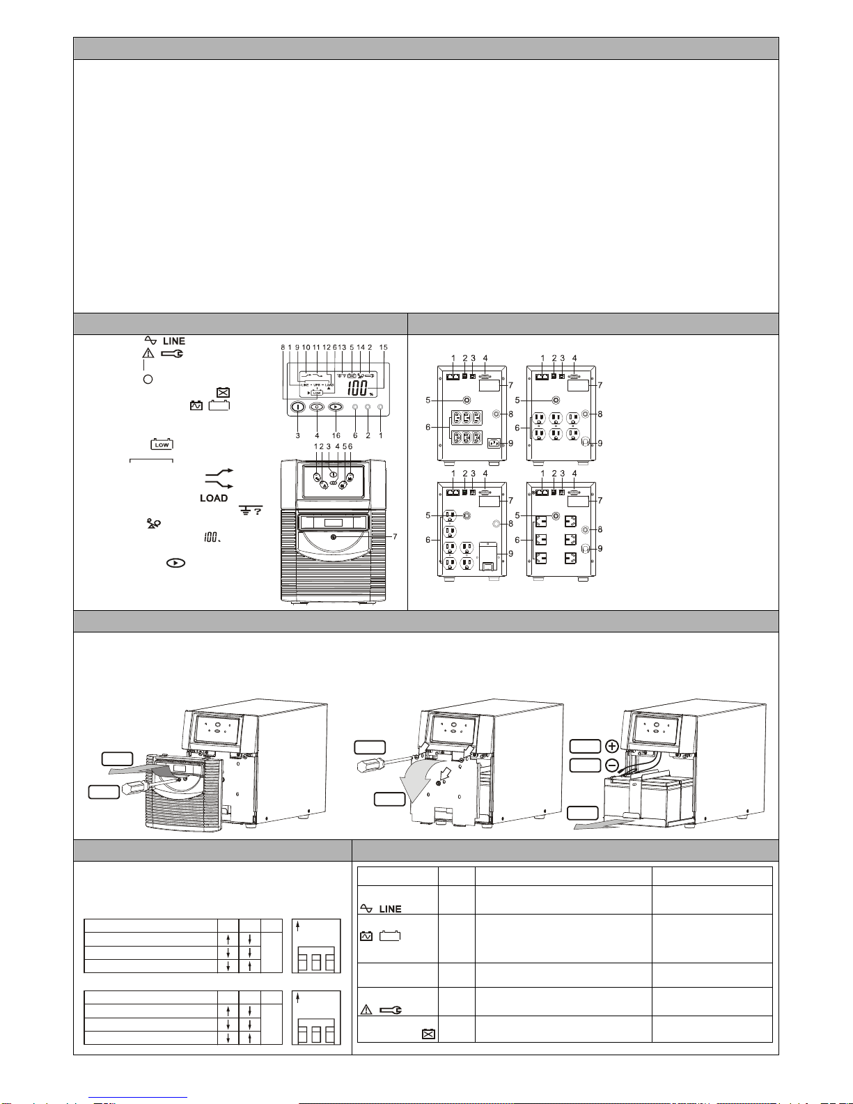
3 Connect the loads
First, connect the UPS with Utility, then plug the
loads into the outlets on the rear of the UPS. To
use the UPS as a master “On/Off” switch, make
sure that all of the loads are switch “On”.
These UPS outlets provide battery power and
surge protection to the equipment when utility
voltage is outside acceptable limits.
Caution: Do not connect a laser printer to the
UPS outlets.
4 Connect Computer
Interface Port
Connect the supplied interface cable (RS-232 or
USB, Optional) to the interface port on the rear of
the UPS and the computer interface port. See
software installation guide in the CD-ROM
(Optional) for installation purpose.
5 Connect Network
Surge protection
Connect a 10 base-T / 100 base-T network cable
into the RJ-45 network surge protection “IN” jack
on the rear of the UPS. Connect from the “OUT”
jack with network cabling to network equipment.
6 UPS Start Up
1. Connect the UPS to the wall receptacle and wait approximately 5-6 seconds, Amber LED should
flash to indicate charging.
2. Push the “On” Switch on the front panel of the UPS until Buzzer sounds, then release.
3. The LCD Display lights up along with an LED. If Utility is normal, the UPS will run under Utility
mode (Green LED). On the contrary, the UPS will run under Backup mode (Solid Amber LED) and
the buzzer alarms every 2 seconds in case of blackout or over/under voltage.
Caution:
1. The UPS “On” will not be executed if the above procedure is not done completely, which means
the buzzer has commenced to sound.
2. The UPS will remain at “NO” output, if the start-up operation is not proceeded properly even
though the Input Power Cord is connected to the wall receptacle.
IMPORTANT NOTICE:
Plug the UPS into the wall receptacle to charge the UPS for over 8 hours after initial installation.
STORAGE:
Store at -15 to +30 °C (+5 to +86 °F), charge the UPS battery every six months.
Store at +30 to +45 °C (+86 to +113 °F), charge the UPS battery every three months.
192321362000004
IN
OUT

Operation Test
Turn Off the UPS
Push the “Off” Switch for at least 3 seconds to turn off the UPS. If you press the “Off” Switch less than 3 seconds, the UPS will not execute shutdown
command due to insufficient pressing time.
In some occasions, the UPS will shut itself down in case of overload, output short-circuited or battery cutoff point reached in the Backup mode.
The UPS will automatically shut off the output and beep for 5 seconds then completely shut itself down.
Plug-in Charge
If the Input Power Cord is connected to the wall receptacle properly and the utility is normal, the UPS will start to charge automatically without
processing “Turn On” procedure. This is indicated by a flashing amber LED. You have to charge for at least 8 hours every 3 months to prevent the
battery from over-discharge when the UPS is in an idle condition.
Auto-Restart
The UPS will automatically restart to provide power to the output if the utility recovers after battery end cutoff or UPS shutdown message provided by
software. On the contrary, the UPS will not auto-restart if it has been turned off by switch or shutdown due to overload or short-circuit. You are
required to start up the UPS manually. If you don’t need UPS auto-restart, you can turn off the UPS by proceeding the “Turn Off” procedure.
Alarm Silence
The Alarm might be turned off by pushing the “On” Switch for approximately 1 second in the “Backup” mode. Unless any other warning or fault condition
occurs, the alarm remains at Silence condition once the “Alarm Silence” is turned off.
Test
Under Normal Utility condition, push the “On” Switch for 3 seconds to execute the Battery Self-test function. In case the battery is normal, it will enter
into Battery Backup Mode for 10 seconds then return back to Utility Mode. If the battery voltage is detected lower than set limit, the Battery
Replacement LED will blink for 5 seconds then extinguish to stop self-test procedure. And if battery is detected weak or dead, the Battery
Replacement LED will steadily illuminate.
FRONT PANEL EXPLANATIONS
REAR PANEL EXPLANATIONS
1. Utility LED
2. Fault LED
3. On Switch
4. Off Switch
5. Battery Replacement LED
6. Battery Backup LED
7. Screw for Easy Swappable Battery
Cover
8. Battery Low
9. Bypass
10. Utility Low, UPS Boost
11. Utility High, UPS Buck
12. UPS Output Indicator
13. Polarity Error or Ground Fault
14. Over load
15. Load/Battery Level(%)
16. Load/Battery Level Indication
Control Button
1. RJ45 Port
2. DIP Switch
3. USB Communication Port
4. RS232 Communication Port
5. Output Breaker
6. Outlet
7. Rating Label
8. Input Fuse
9. Input Power Cord(Inlet)
REPLACING THE BATTERY
Note: Once the battery is disconnected, the loads are not protected from power outages.
When the Battery Replacement LED(Red) lights up, you may leave the UPS to be re-charged for at least 8~10 hours to see whether the
Red LED will be extinguished after the Self-test Function is executed again. In case the Red LED remains unchanged, you may unscrew
the Easy Swappable Battery cover, replace a new battery than push the “On” Switch to disable the RED LED. Please follow the steps 1-7
to replace the new battery
DIP SWITCH SETTING INDICATORS & ALARMS
The voltage of the UPS might be re-set by the DIP Switch
on the rear panel of the UPS. The following charts may
bring you clear pictures about how the settings are done by
the DIP Switch.
Indicator Color Description Alarm
Utility Mode
Green
S
teady:
Output Load is supplied by Utility. None
Backup Mode
Amber Steady (with alarm):
Output Load is supplied by Battery. Every 2 seconds beep
before battery Low and
every 1 second beep
before battery Cut off.
Charging Mode Amber Blinking every second (no alarm)
Battery charge (utility available) None
Fault
Red When Overload, short circuit or
Output VoltageAbnormal occurs Buzzer beeps
continuously.
Battery
Replacement Red Steady: Battery is dead. None
STEP 1
STEP 2 STEP3
STEP 4
STEP 5
STEP 6
STEP 7
FUNCTION
VOLTAGE=220V
VOLTAGE=230V
VOLTAGE=240V
312
N/A
FUNCTION
VOLTAGE=110V
VOLTAGE=115V
VOLTAGE=120V
312
N/A
DIP ON
321
DIP ON
321
This manual suits for next models
3
Table of contents