Rampage EZCRG User manual

EZCRG
Owner’s Manual

A. Introduction
The EZCRG is a self-contained entertainment center in your vehicle which
makes your road trips enjoyable. This versatile floor console incorporates a
high brightness 5” color TV and vertical eject Video Cassette Player, complete
with a built-in speaker, a built-in foil antenna, headphone jacks,AV input jacks,
AV output jacks and a universal remote control.
Installedbetweenthedriverandpassengerfrontseats,withafloormounting plate
available for most cars, vans and trucks. This aesthetic console is constructed
oftwo-tone, graytextured plasticwith anextra cupholder, jackcover, protective
bar and cigarette lighter jack to compliment your vehicle’s decor. The EZCRG
standardmanufactureensures reliabilityandlongevity. Pleasereadthefollowing
instructions thoroughly for correct installation and proper operation. Store this
manual in a convenient and safe place for future reference.
B. Precaution
1. Use only good quality VHS tapes and discard worn out tapes to prevent video
head clogging. If the heads get dirty over a period of time during normal
operation of the VCP, and the automatic tracking control will not remove the
snow from the picture we recommend using a cleaning cartridges sparingly
to restore normal picture.
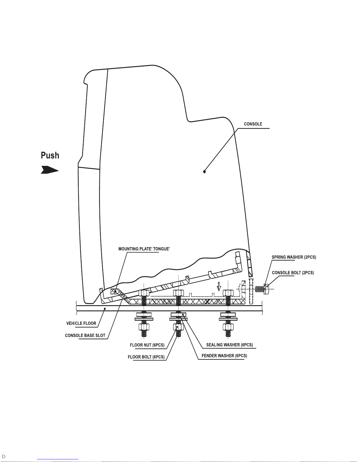
2. In order to maintain a safe mounting arrangement, this console must be
secured to the floor of the vehicle according to Installation Guide contained in
this manual. Failure to do so may result in the console becoming a projectile
in the event of an accident.
3. Beforeworkingunderthevehicle,blockthewheelstopreventaccidentalinjury.
4. Before drilling any holes in the vehicle, verify that the drill bit will not enter into
theframerail(s)ofthevehicleofdamageelectricalwires,fuellines,brakelines,
hoses, exhaust system components or any other items that will impair that
operationofthe vehicle. Theconsole must besecured to thefloor panelof the
vehicle. Check under the vehicle to ensure that the holes will be in the
properlocations. Alsocheckunderthecarpettoensurethattherearenowiring
harnesses,fuellines,etc.thatcouldbedamagedwhendrillingthroughthefloor
pan of the vehicle.
CAUTION: Children should not be allowed to wear headphones unless
carefully supervised. The headphone wires may become
entangled and induce choking.
5. Do not use gasoline, thinners or other thinning liquids to clean the unit.
Remove dust and stains with a damp cloth.
6. Do not cover the unit with a cloth during operation; the internal temperature
will rise and may damage the unit.
2

7. In case anything falls into the cabinet, unplug the unit and have it checked by
qualified personnel prior to further operation.
8. Only use the supplied power cord, and not use other power supplies even if
they have the same current characteristics.
9. Always unplug the unit from the cigarette lighter socket of the vehicle if you do
not intend to use it for an extended period of time. In addition, first disconnect
the cord from the cigarette lighter socket before disconnecting the cable
from the 4-PINsocketonthebackof theunit;neverdisconnectthecablefrom
the unit connector by pulling the cord.
10. Always remove the VHS tape from the unit after use.
11. To avoid electrical hazards, do not disassemble the cabinet.
12.Due to the nature of TV signals, vehicle motion, direction the vehicle is facing,
distance from nearby transmitter, nearby surroundings and weather may
adversely affectTVreception.Theseconditionsmayresultin pictureroll,poor
reception (snowy picture) and momentary loss of color (especially when the
vehicle is in motion).
C. Legend for Figure 1
1. Picture Button
2. Auto Program Button
3. TV/AV Button
4. Volume Up and Down Buttons
5. Channel Up and Down Buttons
6. Infrared Remote Control Sensor
7. Power Button
8. Auto Repeat Button
9. Rewind Button
10. Stop/Eject Button
11. (Fast) Forward Button
12. Play Button
13. Headphone Jack #1
14. Video Input Jack
15. Audio Left Input Jack
16. Audio Right Input Jack
17. Headphone Jack #2
18. Speaker Holes
19. Tape Door
20. Protective Bar
21. Cigarette Lighter Jack
22. Jack Cover
3Figure 1

NOTE: Whenever unit loading exceeds 3 Amperes, the unit power supply
will overload and automatically disconnect the power supply from
+12V DC vehicle power at the cigarette lighter jack.
D. Contents in Kit
TV and VCP Floor Console
Owner’s Manual
Remote Control
12V Cigarette Lighter Cord and Plug (for powering this unit)
CardboardMountingTemplate(forpositioning themountingholesonthe floor)
Hardware Package for Securing Console to Vehicle Contains the following:
6 Floor Bolts
6 Sealing Washers
6 Fender Washers
6 Floor Nuts
2 Console Bolts
2 Spring Washers
1 Mounting Plate
E. Tools Required (not supplied)
Electric Drill
1/8” Steel Drill Bit
1/4” Steel Drill Bit
Socket Wrench Set with Deep-Wall, 7/16” Socket
Box Wrench, Size 7/16”
Standard Utility Knife (or Equivalent)
NOTE: Two people are required for installation.
F. Installation Guide (Refer to Figure 2)
1. Temporarily place the cardboard mounting template on an appropriate
mounting location on the floor between driver/passenger seats, with the
rounded end of the template facing the front of your vehicle. Make sure
that you have checked both underneath the vehicle and within the vehicle
(under the carpet) for obstructions.
2. Drill 6 small 1/8” pilot holes though the marks on the template to verify
that the holes are in the proper locations.
3. After verifying that the 1/8” pilot holes are in the proper locations, use
the 1/4” drill bit to enlarge the pilot holes.
4. Remove the template and replace it with the mounting plate on the floor
over the drilled holes.
5. Place the 6 floor bolts through the mounting plate and into the holes just
drilled. 4

5
Figure 2
a

6. Place1 sealingwasher(rubber sidetowardsvehicle floor)and1 largefender
washer over each of the floor bolts and attach the floor nuts. In addition to
the sealing washer, it may be desirable to place a small circle of silicon
sealer around the hole under the vehicle before installing the washers and
nut, to further prevent moisture from getting into the vehicle.
7. Tighten thefloornutsdown securely. Havethe 2ndpersoninsidethevehicle
hold the floor bolts securely with the box-end wrench, while the person
underneath the vehicle tightens down the floor nuts.
8. Press the latch of the door at the rear of the console to the right and open
the door. Then set the console on the mounting plate, with the slot of the
console base pointing to the tongue end of the mounting plate, and the two
holesin therear oftheconsole pointingto thetwo holesin theupright endof
the mounting plate.
9. Apply a firm push forward to mate the console base and the floor mounting
plate, with the tongue of the mounting plate projecting into the slot of the
console base.
10.Place the spring washer on the 2 console bolts.
11. Place the console bolts through the mounting plate and into the two holes at
the rear of the console base.
12.Tighten the console base bolts with a Phillips screwdriver.
G. Powering the unit (Refer to Figure 3)
NOTE: Have all the wires, such as the power cord,AV cables and external
antenna cable, or CATV cable, pass through the two notches at the
bottom of the door.
Plug the cigarette lighter cord into the 4-PIN DC input jack on the back of the
console. Then reinstall the console rear door and press the latch to close the
door. Plug the other end into the cigarette lighter receptacle in the vehicle.
NOTE: If the unit draws in excess of 10 Amperes, the power supply will
deactivate and turn off the unit.
6

7
Figure 3
DOOR
DOOR LATCH
CABLE NOTCHES
DC 12V INPUT
ANTENNATERMINAL
ANTENNA JACK NUT
ANTENNA JACK OF FOIL DIPOLE
DC 12V
DETAIL
VIDEO L AUDIO R
OUTPUT

8
H. Connecting an External Antenna (Refer to Figure 3)
1. Originally, the antenna jack of the built-in foil dipole has already been
connectedtotheantennaterminalbehindthedoorattherearoftheconsole.
2. In case of poor images with the foil dipole, loosen the nut around the an-
tenna jack, unplug the antenna jack, and connect the coaxial cable of an
external antenna to the antenna terminal.
3. In addition to normal broadcast reception of VHF and UHF channels, you
can connect the CATV cable directly to the antenna terminal for
CH1 ~ CH125 reception.
I. Watching TV
1. Press the power button to turn on the unit. The unit will enter the mode last
committedtomemory. PresstheTV/AVbuttonto selectthedesiredTVmode.
2. Press the auto program button to automatically search and store the chan-
nels using the on-screen display. When the channel number on the screen
turns from red to green, the unit starts to play the 1st channel automatically.
Press the channel up and down buttons to access your desired channel.
3. Adjust the volume controls for individual preference. If the picture needs to
be adjusted, use the picture button to illuminate the on-screen display for
contrast,brightness, colorand tintin sequence,anduse thevolume buttonto
adjust each function up or down.
J. Watching a Movie
1. With power applied to the unit, select theAV mode by pressing the TV/AV
button, and push the tape cassette gently into the compartment of the VCP.
You will feel the automatic pull on the cassette as it is loaded and the VCP
will go into the play mode automatically.
2. You may carry out the procedure indicated in Step 3 for Watching TV.
3. Press the (fast) forward or rewind button to scan forward or backward, and
press it again to increase the speed.
4. Press the play button to resume the normal playing mode.
5. Pressing theauto repeat buttonactivatesthe repeatplay function.When the
tape reaches the end, the VCP will automatically rewind the tape to the
beginning and then repeat tape play. Pressing this button again deactivates
the repeat function.
6. Press thestop/eject buttonto stoptheplaying, andpress itagain toeject the
tape.
NOTE: DEW Indicator
The word DEW will be displayed on the screen to indicate excessive moisture

has accumulated inside of VCP. In this case, the VCP will not operate, and
no VCP controls will be functional, except for the VCP power button on the
remote control, until the unit dries out sufficiently and the word DEW
disappearsfrom thescreen. When DEWmodehasbeenactivated, leavethe
VCPon to allow it to dry out completely. This will take approximately 1 hour.
K. Playing a video game
Plug the video output from your game into the yellow video jack, and the audio
L and audio R into the corresponding audio jacks.
L. Sending AV signals (Refer to Figure 3)
To send AV signals from this floor console to an external monitor, connect the
AV output jacks on the rear of the console to the external monitor input jacks,
after opening the rear door.
M. Using a Headphone
Inserting the plug of your headphone to the number 2 headphone jack on the
frontofthefloorconsolepermitsbothspeakerandheadsetsoundsimultaneously.
Using the number 1 headphone jack cuts off (mutes) the speaker audio.
N. Remote Control Operation (Refer to Figure 4)
9
Figure 4

10
1. TV POWER Button
Press this button to switch the unit on or off .
2. Number Buttons (0-9)
Press these buttons to make a direct TV channel selection. The channel
number chosen will be displayed on the screen for about 4 seconds.
3. SKIP/SEARCH Button
a. Press this button until SKIP MODE ON is displayed on the screen.
Then use the channel up and down buttons’; the TV will stop only on the
active TV channels.
b. Presstheskip searchkeyuntilSKIPMODE OFFisdisplayedon thescreen.
Then all the TV channels will be shown using the channel up and down
buttons.
4. TV/CATV Button
Pressthis buttonto selecttheregular 69-channelBroadcast TVandthe 125-
Channel Cable TV (Standard Cable, HRC Cable, and IRC Cable) with the
on- screen display.
5. VCP POWER Button
Plug in the unit; the power indicator will turn on. Press this button to switch
the VCP on or off . The indicator will be brighter when the unit is on.
6. REW Button
a. Press this button once in the playback mode, the VCP enters the reverse
picturesearch modeand thetape willrewindrapidly withthe pictures.The
rewind indicator lamp will blink. Press this button once more, and the tape
will rewind at a high speed with the lamp blinking more quickly.
b. Pressthis buttonin thestopmode; thetape willrewindat avery highspeed
without any picture and sound.
c. Press this button once in the (fast) forward mode; the VCP enters the
reverse picture search mode and the tape will rewind rapidly with the pic-
tures. The rewind indicator lamp will blink. Press this button once more,
and the tape will rewind at a high speed.
7. F. FWD Button
a. Press this button once in the playback mode; the VCP enters the forward
picture search mode and the tape advances rapidly with the pictures. The
fast forward indicator lamp will blink. Press this button once more, and the
tape will advance at a high speed with the lamp blinking more quickly.
b. Press this button in the stop mode, the tape will advance at a very high
speed without any picture and sound.
c. Press this button once in the (fast) rewind mode; the VCP enters the for-
wardpicturesearch modeand the tapeadvances rapidly withthe pictures.
The fast forward indicator lamp will blink. Press this button once more, and
the tape will advance at a high speed.

11
8. TV/VIDEO Button
Press this button to select theTV mode and theAV mode in turn. When the
power turns on, the unit will go to the mode last stored in memory.
9. MUTE Button
Press this button to cut off all sound. Pressing this button again restores
soundto thepreviouslyset level.Mute mayalsobe canceledby pressingthe
volume up and down buttons.
10. CH Up Button
Press this button to increment the TV channel number.
11. CH Down Button
Press this buttons to decrement the TV channel number.
12. VOL Up Button
Press this button to increase the sound level.
13. VOL Down Button
Press this button to decrease the sound level.
14. PICTURE SELECT Button
Press this button to illuminate the on-screen display for contrast, bright-
ness,color andtint insequence, andpress thevolume upanddownkeysto
adjust each function up or down.
15. AUTO MEMORY Button
Press this button to automatically search the stored channels using the
on-screen display. When the channel number on the screen turns from red
to green, the unit starts to play the first channel automatically.
16. ERASE/WRITE Button
ToeraseaTVchannel,pressthisbuttonuntilMANUALMEMORYhas“erase”
displayed on the screen. To store a TV channel, press this button until
MANUALMEMORYhas“add”displayed onthe screen.The storedchannel
numbersare displayedin greenon thescreen whilethe non-storedchannel
numbers are in red.
17. PLAY Button
Press this button in the stop mode to playback a tape. You can also press
this key to release special operations such as the search modes.
18. STOP Button
Press this button to stop tape, and press it once more to eject the tape.
19. REPEAT Button
Press the auto repeat button to activate this function. The tape is rewound
automatically to the beginning after playing to the end. In this mode, all
controls, except for the power button, are disabled. Press this key once
more to deactivate this function.

O. Specifications
System NTSC
Picture Size 5 inches
Remote Control Infrared rays
Antenna Built-in foil dipole
Channels 2-6 (VHF low), 7-13 (VHF high),
14-69 (UHF), 1-125 (CATV)
Plugs 2 x Headphone jacks (3.5mm),
RCA A/V input jacks
RCA A/V output jacks
4 PIN DC jack
Cigarette lighter jack
External antenna terminal
Audio track 1 track
Tape width 12.7 mm
Tape speed SP 33.35 mm/s
Playback time 180 minutes with T-180
set to SP mode
FF/REW time Less than 7 minutes with T-120
Heads 2 helical scanning system
Video Output 1.0 Vp/p, 75 ohm, unbalanced
Video signal-to-noise ratio Better than 40 dB
Audio output 3 W
Audio signal-to-noise ratio SP Better than 30 dB
Frequency response SP 100 Hz-7 kHz
PowerSupply DC 12 V
Power Consumption 30 W
OperatingHumidity 10 ~ 75%
Operating Temperature 41 ~ 104 degrees Fahrenheit
(5 ~ 40) centigrade
Storage temperature 4 ~ 140 degrees Fahrenheit
(-20 ~ 60) centigrade
Dimensions Inches (mm) (W x H x D) 7.0 (178) x 17.75 (451) x 15.75 (401)
Weight 8.55 kilograms
© 2001 Audiovox Electronics Corp., 150 Marcus Blvd., Hauppauge, NY, 11788 128-6016A
This manual suits for next models
2
Table of contents
Other Rampage Car Receiver manuals

Rampage
Rampage ACD-28 Programming manual

Rampage
Rampage 1285300F User manual

Rampage
Rampage Rampage ACD-20 Safety guide

Rampage
Rampage 1285780E User manual

Rampage
Rampage ACD-12 User manual

Rampage
Rampage ACD-27 Programming manual

Rampage
Rampage AV-301N User manual

Rampage
Rampage ACD-83 User manual

Rampage
Rampage ACD-16 User manual

Rampage
Rampage ACD-83 User manual