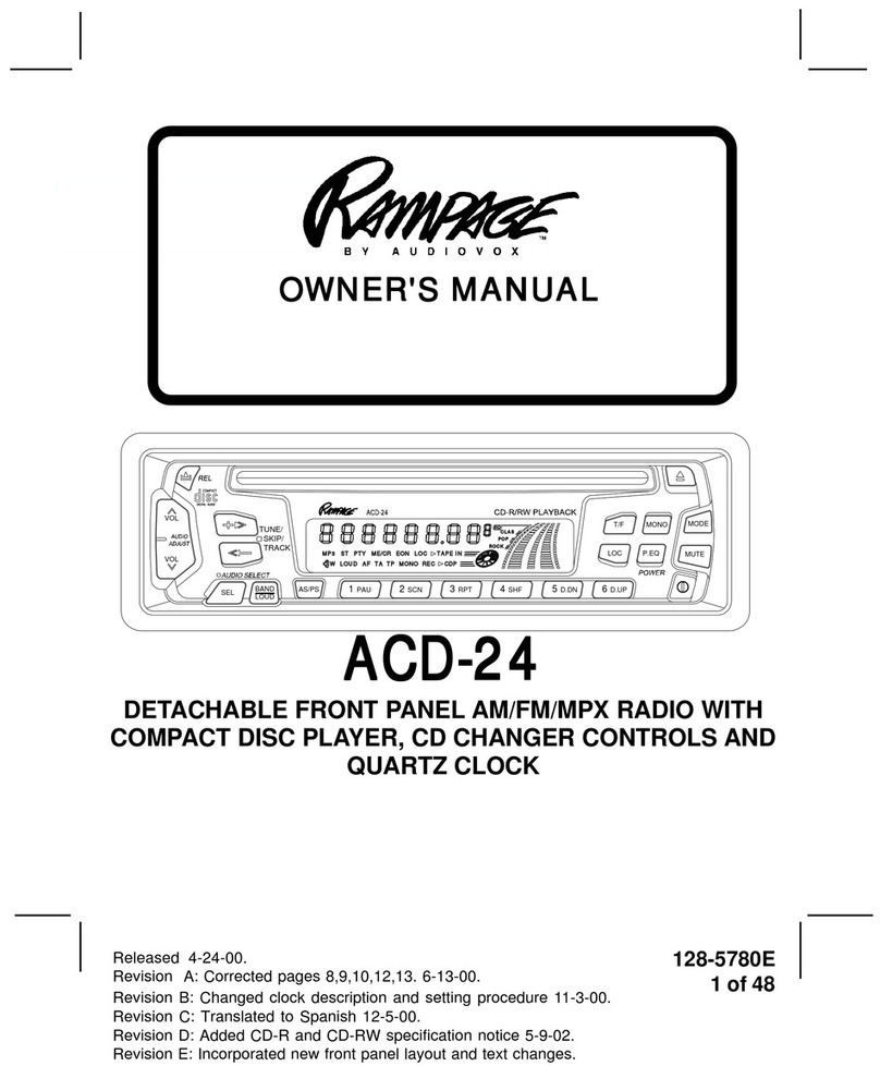
Rampage 1285300F User manual

.
.
ACD-22ACD-22
ACD-22ACD-22
ACD-22
AM/FM/MPX RADIO
WITH DETACHABLE FRONT PANEL,
COMPACT DISC PLAYER
AND QUARTZ CLOCK
LOUD
BAND
1
PAU
2
SCN
3
RPT
456
MODE PWR
SEL
VOL
VOL
CONTROL
SHF
EQ
AS
PS
CD-R/RW PLAYBACK
LEVEL METER
OWNER'S MANUAL
MANUEL DE L'UTILISATEUR
MANUAL DE OPERACION

22
22
2
INSTINST
INSTINST
INSTALLALL
ALLALL
ALLAA
AA
ATT
TT
TION INSTRUCION INSTRUC
ION INSTRUCION INSTRUC
ION INSTRUCTT
TT
TIONSIONS
IONSIONS
IONS
INSTALLATION INSTRUCTIONSINSTALLATION INSTRUCTIONS
INSTALLATION INSTRUCTIONS
This unit is designed for installation in cars, trucks, and vans with an existing radio opening. In many cases,
a special installation kit will be required to mount the radio to the dashboard. These kits are available at
electronics supply stores and car stereo specialist shops. Always check the kit application before purchasing to
make sure the kit works with your vehicle. If you need a kit but cannot find it available, call our toll-free “HELP” line
(1-800-645-4994).
UNIVERSALINSTALLATIONPROCEDUREUSINGMOUNTINGSLEEVE
1. Remove the detachable front panel if it is attached to the chassis by pushing the “Release” button. Slide the
mounting sleeve off of the chassis. If it is locked into position, use the removal tools (supplied) to disengage it.
2. Checkthedashboardopeningsizebyslidingthemountingsleeveintoit. Iftheopeningisnotlargeenough,carefully
cut or file as necessary until the sleeve easily slides into the opening. Do not force the sleeve into the opening
or cause it to bend or bow. Check that there will be sufficient space behind the dashboard for the radio chassis.
3. Locate the series of bend tabs along the top, bottom, and sides of the mounting sleeve. With the sleeve
fully inserted into the dashboard opening, bend as many of the tabs outward as necessary so that the
sleeve is firmly secured to the dashboard.
4. Place the radio in front of the dashboard opening so that the wiring can be brought through the mounting
sleeve. Follow the wiring diagram carefully and make certain all connections of the wiring harness are
secureand insulatedwith wire nutsor electricaltape toinsure properoperation ofthe unit. Aftercompleting
the wiring connections, attach the front panel and turn the unit on to confirm operation (ignition switch must
be “on”). If unit does not operate, re-check all wiring until problem is corrected. Once proper operation is
achieved, turn off the ignition switch and proceed with final mounting of the chassis.
5. Carefully slide the radio into the mounting sleeve making sure it is right-side-up until it is fully seated and
the spring clips lock it into place.
6. Attach one end of the perforated support strap (supplied) to the screw stud on the rear of the chassis using
the hex nut provided. Fasten the other end of the perforated strap to a secure part of the dashboard either
above or below the radio using the screw and hex nut provided. Bend the strap to position it as necessary.
CAUTION: The rear of the radio must be supported with the strap to prevent damage to the dashboard from
the weight of the radio or improper operation due to vibration.
7. Re-attach the front panel to the chassis and test radio operation by referring to the Operating Instructions for
theunit.
INSTALLATIONUSINGKITS
1. If your vehicle requires the use of an installation kit to mount this radio, follow the instructions included with
the installation kit to attach the radio to the mounting plate supplied with the kit.
2. Wire and test the radio as described in Step 4 above.
3. Install the radio/mounting plate assembly to the sub-dashboard according to the instructions of the installation kit.
4. Attach the support strap to the radio and dashboard as described in Step 6 above.
5. Replace the dashboard trim panel.
ISOINSTALLATIONPROCEDURE
This unit has threaded holes in the chassis side panels which may be used with the original factory mounting
brackets of some Toyota, Nissan, Mitsubishi, Isuzu, Hyundai and Honda vehicles to mount the radio to the
dashboard. Please consult with your local car stereo specialist shop for assistance on this type of installation.
1. Remove the existing factory radio from its dashboard or center console mounting. Save all hardware and
brackets as they will be used to mount the new radio.
2. Carefully un-snaptheplasticframe fromthefrontof thenewradiochassis. Removeanddiscard theframe.
3. Remove the factory mounting brackets and hardware from the existing radio and attach them to the new radio.
CAUTION: DONOTEXCEEDM5X8MMMAXIMUMSCREWSIZE.
LONGERSCREWSMAYTOUCHANDDAMAGECOMPONENTSINSIDETHECHASSIS.
4. Wire the new radio to the vehicle as per step 4 above.
5. Mount the new radio assembly to the dashboard or center console using the reverse procedure of step 1.

INSTINST
INSTINST
INSTALLALL
ALLALL
ALLAA
AA
ATT
TT
TION INSTRUCION INSTRUC
ION INSTRUCION INSTRUC
ION INSTRUCTT
TT
TIONSIONS
IONSIONS
IONS
8:30AM - 7PM
9AM - 5PM
CENTRAL EASTERN
6:30AM - 5PM
7AM - 3PM
MOUNTAIN
5:30AM - 4PM
6AM - 2PM
PACIFIC
MON. - FRI.
SATURDAY
DAY TIME ZONE
TOLL-FREE INSTALLATION ASSISTANCETOLL-FREE INSTALLATION ASSISTANCE
TOLL-FREE INSTALLATION ASSISTANCE
The installation and wiring connections for this unit are so simple, we doubt you'll need our help, but, if you
do, we're here to help you. Just call our toll-free telephone assistance line at 1-800-645-4994 during the days
and hours shown (U.S.A. and Canada only).
7:30AM - 6PM
8AM - 4PM
FASTEN THIS END TO
SCREW STUD ON REAR
OF CHASSIS
NUT (5MM)
FASTEN THIS END TO SECURE PART OF
DASHBOARD. DRILL HOLE IF NECESSARY.
SCREW
(5MM)
DETACHABLE
FRONT PANEL
EXISTING DASH OPENING
FILE EDGES TO FIT IF NECESSARY - DO NOT OVERFILE
NOTE: IF DASH IS SOLID, USE REAR SIDE (WITHOUT THE
LIP) OF MOUNTING SLEEVE AS A TEMPLATE & CUT
OPENING
UNIVERSALINSTALLATIONUSINGMOUNTINGSLEEVEUNIVERSALINSTALLATIONUSINGMOUNTINGSLEEVE
UNIVERSALINSTALLATIONUSINGMOUNTINGSLEEVE
NUT (5MM)
REMOVE THE PLASTIC FRAME FROM THE FRONT OF
THE CHASSIS BY CAREFULLY UN-SNAPPING IT.
TYPICAL INSTALLATION
ISO INSTALLATIONISO INSTALLATION
ISO INSTALLATION
20° MAX.
FRONT PANEL
CAUTION:
FOR PROPER OPERATION OF THE CD PLAYER, THE
CHASSIS MUST BE MOUNTED WITHIN 20° OF
HORIZONTAL. MAKE SURE THE UNIT IS MOUNTED
WITHIN THIS LIMITATION.
SIDE VIEW
OF
CHASSIS
33
33
3
UN-SNAP AT 2 PLACES
EACH ON TOP AND BOTTOM
MAXIMUM
SCREW SIZE
M5 x 8
MAXIMUM
SCREW SIZE
M5 x 8
PERFORATED STRAP
RADIO
SCREW STUD
MOUNTING SLEEVE
PLASTIC FRAME
FACTORY MOUNTING
BRACKETS
REMOVAL TOOLS
BEND BOTTOM
TABS DOWNWARD
BEND TOP
TABS UPWARD

44
44
4
RR
RR
RAA
AA
ADIO WIRINGDIO WIRING
DIO WIRINGDIO WIRING
DIO WIRING
RADIOWIRINGRADIOWIRING
RADIOWIRING
REFER TO PAGE 4 FOR SPEAKER WIRING
IMPORTANT
THE BLUE WIRE CAN BE USED TO
REMOTELY ACTIVATE AN AUTOMATIC
ANTENNAORANEXTERNALAMPLIFIER
(SEE ANTENNAORAMPLIFIERMANUAL)
ANTENNALEAD
ON REAR OF RADIO 9 PIN PLUG
(SEE PAGE 4 FOR SPEAKER WIRING)
POSITIVE (+) TERMINAL
12 VOLT BATTERY
METAL PART OF DASH
(DRILL HOLE IF NECESSARY)
SCREW
BLACK
RED
EXISTING
ANTENNA
CABLE
BLUE
ANTENNA AUTOMATIC
ANTENNA
FUSEBLOCK
IMPORTANT
YELLOW WIRE MUST BE CONNECTED
ASSHOWNORRADIOWILLNOT
OPERATEPROPERLY
4-PIN PLUGS
YELLOW
CARBATTERY
“RADIO” FUSE
+12VACCESSORY

55
55
5
SPESPE
SPESPE
SPEAA
AA
AKK
KK
KER WIRINGER WIRING
ER WIRINGER WIRING
ER WIRING
SPEAKERWIRINGSPEAKERWIRING
SPEAKERWIRING
REFER TO PAGE 3
FOR RADIO WIRING
RCAJACKS
LINEOUT
FORUSEWITH
OPTIONAL
EXTERNAL
AMPLIFIERS
RED=RIGHTREAR
WHITE=LEFTREAR
WHITE w/BLACK
STRIPE
WHITE
LEFTFRONT SPEAKER RIGHT FRONT SPEAKER
LEFTREAR SPEAKER RIGHT REAR SPEAKER
GREEN
GRAY w/BLACK STRIPE
9-PINPLUGS
GREEN w/BLACK STRIPE
WARNING!
lTHE AMPLIFIERS IN THIS RADIO ARE ONLY DESIGNED FOR USE WITH 4 SPEAKERS.
lNEVER COMBINE (BRIDGE) OUTPUTS FOR USE WITH 2 SPEAKERS.
lNEVER GROUND NEGATIVE SPEAKER LEADS TO CHASSIS GROUND.
lFAILURE TO WIRE EXACTLY AS SHOWN BELOW MAY CAUSE ELECTRICAL
VIOLET w/BLACK
RADIO
8:30am - 7:00pm Eastern
9:00am - 5:00pm Eastern
Monday - Friday
Saturday
1-800-645-49941-800-645-4994
1-800-645-49941-800-645-4994
1-800-645-4994
HELP!
GRAY
VIOLET
4-PIN PLUGS
SEE PAGE 3 FOR
RADIO WIRING

1POWERON/OFFBUTTON(PWR)
Press this button to turn the unit on and off.
The unit will also turn on automatically when
a disc is loaded, or when any other button is
pressed.
2VOLUME/LEVELCONTROLS
To increase the volume level, press the
button. The volume will increase and the
level will be shown on the display panel
from a minimum of VOL 00 to a maximum
of VOL 100. To increase the volume
quickly, keep the button pressed. To de-
crease the volume level, press the but-
ton. Keep the button pressed to decrease
the volume quickly. Thedisplaywill automati-
cally return to the normal indication 5 sec-
onds after the last volume adjustment or
whenanother function is activated. These
controls are also used in conjunction with
the Select (SEL) button 3to adjust the
bass, treble, balance and fader levels as de-
scribed in 4, 5, 6, and 7.
3SELECTBUTTON(SEL)
This button is used to select the audio
function (volume, bass, treble, balance or
fade) to be adjusted using the Level Control 2.
Pressing the Select button once will set the unit
for volume adjustment (VOL will appear on the
display panel). Pressing the button additional
times will select bass adjustment (BAS on
display panel), treble adjustment (TRB), balance
(BAL),fader(FAD),andvolume(VOL) again. The
display will return to the normal indication 5
seconds after the last adjustment or when an-
other function is activated.
4BASSCONTROL
To adjust the bass level, first select the Bass
mode by pressing the Select button 3until the
BAS indication appears on the display panel.
Within 5 seconds of choosing the Bass mode,
press the or buttons of the Level Control
2to adjust the bass response as desired. The
bass level will be shown on the display panel
from a minimum of B--10 to a maximum of B 10
(B 00 represents flat response). The display
will automatically return to the normal indication 5
seconds after the last adjustment or when
another function is activated. Adjusting the bass
level will automatically return the equalizer set-
ting to the FLAT mode from its previous setting.
66
66
6
OPEROPER
OPEROPER
OPERAA
AA
ATT
TT
TING INSTRUCING INSTRUC
ING INSTRUCING INSTRUC
ING INSTRUCTT
TT
TIONSIONS
IONSIONS
IONS
3, 4, 5, 6, 7 8,10
13
22 23 24 25
17 18 26
16
15
27
19 1
12
14
20,21
2
30
29
11
28
9
LOUD
BAND
1
PAU
2
SCN
3
RPT
456
MODE PWR
SEL
VOL
VOL
CONTROL
SHF
EQ
AS
PS
CD-R/RW PLAYBACK
LEVEL METER

66
66
6
5TREBLECONTROL
To adjust the treble level, first select the Treble
mode by pressing the Select button 3until
the TRB indication appears on the display
panel. Within 5 seconds of choosing the
Treble mode, press the or buttons of the
Level Control 2to adjust the treble response as
desired. The treble level will be shown on the
display panel from a minimum of TRB--10 to a
maximum of TRB 10 (TRB 00 represents flat re-
sponse). The display will automatically return
to the normal indication 5 seconds after the
last adjustment or when another function is
activated. Adjusting the treble level will automati-
callyreturn theequalizersetting totheFLATmode
from its previous setting.
6LEFT/RIGHTBALANCECONTROL
To adjust the left-right speaker balance, first select
the Balance mode by pressing the Select button
3until the BAL indication appears on the display
panel. Within 5 seconds of choosing the Balance
mode, press the button of the Level Control 2
to adjust the stereo balance to the left channel
speakers or the button of the control to adjust
it to the right channel speakers. The balance position
willbe shown onthedisplaypanelfromBAL10L(full
left) to BAL 10R (full right). When the volume level
between the left and right speakers is equal,
BAL L=R will be shown on the display panel. The
display will automatically return to the normal
indication 5 seconds after the last adjustment or
when another function is activated.
7FRONT/REARFADERCONTROL
To adjust the front-rear speaker balance, first se-
lect the Fader mode by pressing the Select button
3until the FAD indication appears on the display
panel. Within 5 seconds of choosing the Fader
mode, press the or the buttons of the Level
Control 2to adjust the front-rear speaker levels
as desired. The fader position will be shown on
the display panel from FAD 10R(full rear) to
FAD10F(fullfront). Whenthevolumelevelbetween
the front and rear speakers is equal, FAD F=R will
be shown on the display panel. The display will
automatically return to the normal indication 5 sec-
onds after the last adjustment or when an-
other function is activated.
8LOUDNESSCONTOUR(LOUD)
When listening to music at low volume lev-
els,this featurewill boostthe bass and treble
ranges to compensate for the characteris-
tics of human hearing. Press and hold the
BAND/LOUD button for 2 seconds to acti-
vate this feature as indicated by a beep tone
and LOUD ON appearing on the display
panel for about 5 seconds. (LOUD remains
on the display.) Pressing the button again
for 2 seconds will sound a beep tone and
LOUD OFF will appear on the the display for
about 5 seconds.
9AUDIOMUTE
This button is used to mute the volume from
the system. By pressing the button, the indi-
cation MUTE will appear flashing on the dis-
play panel and the volume will be muted.
Pressing the Mute button again or activating
any other function of the unit will return to the
volume level setting in use before the Mute
function was activated.
bl AM/FMBANDSELECTOR
During radio play, each time the button is
pressed, the radio band changes. The indi-
cations AM, F1, F2, or F3 will appear on the
display panel according to your selection.
bm MANUALUP/DOWN( / )AND
SEEKTUNING
Each time the Up Tuning button ( ) is
pressed, the radio will tune higher, seeking
the next strong station and stop. Similarly,
each press of the Down Tuning button
(
) will tune lower and stop at the next
strong station. To manually seek a spe-
cific station, press the button in the appro-
priate direction until the desired frequency
is reached.
Press either button for longer than 2 sec-
onds; MANUAL will appear on the dis-
play. Now, when the Up or Down tuning
77
77
7
OPEROPER
OPEROPER
OPERAA
AA
ATT
TT
TING INSTRUCING INSTRUC
ING INSTRUCING INSTRUC
ING INSTRUCTT
TT
TIONSIONS
IONSIONS
IONS

button is pressed momentarily, tuning will
occur two frequency steps at a time. If either
button is pressed and held in Manual mode
for2 seconds, themanual SeekTuning func-
tion is initiated, whereby the radio will tune
rapidly in the appropriate direction and stop
on, or close to, the desired frequency when
the button is released.
If no further tuning is performed after 5 sec-
onds, AUTO will appear momentarily on the
display, and tuning will revert to the original
tuning mode.
bn AUTO-STORETUNING(AS)
PRE-SETSCANTUNING(PS)
Press this button momentarily to scan the 6
stations in the pre-set memories of the FM
band in use, plus the other two FM bands.
The unit will stop at each pre-set station for
10 seconds before continuing to the next
pre-set station (the frequency on the display
panel will flash during Pre-Set Scan opera-
tion). Press the button again momentarily
to stop Pre-Set Scan operation and remain
on the selected frequency in that band.
Pressing the button for longer than 2 sec-
onds will activate the Auto-Store Tuning fea-
ture. The radio will automatically scan the
band in use and enter strong stations into
the pre-set memory positions for that band.
If you have already set the pre-set memo-
ries of that band to your favorite stations,
activating the Auto-Store Tuning feature will
erase those stations and enter the new
strong stations. This feature is most useful
when traveling in a new area where you are
not familiar with the local stations.
bo STATIONPRE-SETMEMORIES
To set any of the 6 pre-set memory buttons, use
the following procedure:
1.Turn the unit on and select the desired
band.
2.Select the first station to be pre-set using
theUp/Down seek/tuning functions bm.
3.Press the pre-set button to be set and con
tinue tohold the button in. A confirming tone
will be heard and the pre-set number will ap
pear on the display panel. The station is now
set into the memory of that pre-set button and
can be re-called at any time by momentarily
pressing that button.
4.Repeat the above procedure for the remaining
5 pre-sets on the band in use and for the other
3 bands of the unit.
bp EQUALIZERSELECTOR(EQ)
The EQ button applies preset sound effects to the
unit’s audio output signal. The EQ button, when
pressed, will activate one of the following operat-
ingmodes:CLASSICS, POP M,ROCK M,FLAT,or
DSP OFF. Nonetheless, when the EQ function is
active, as displayed (
EQ
----CLAS, POP, ROCK)
on the panel, the bass and treble levels can still
be changed to accommodate the listener’s ear.
When the EQ function is not active, the unit re-
turns to the user-set bass and treble levels. The
FLAT selection indicates no equalizer enhance-
ment of the program, thereby removing the pre-
set sound effects, unless otherwise desired,
while DSP OFF inhibits selection of equalizer
mode enhancement.
bq FMMONO/STEREOSELECT(MONO)
During FM radio operation, this button is used to
select monaural or stereo reception of the
broadcast signal. Under normal reception
conditions, the unit should be left in the stereo
mode as indicated by the icon on the display
panel when tuned to an FM stereo signal. If the
signal is to noisy for comfortable listening, press
the MONO button (the indication will
disappear from the display panel and MONO will
appear).To return to stereo reception mode, press
the button again so that the indication
appears on the display panel.
88
88
8
OPEROPER
OPEROPER
OPERAA
AA
ATT
TT
TING INSTRUCING INSTRUC
ING INSTRUCING INSTRUC
ING INSTRUCTT
TT
TIONSIONS
IONSIONS
IONS
br LOCAL (LOC) BUTTON
This feature is used to select the strength of
the signals at which the radio will stop during
Automatic Seek Tuning. Pressing the button
will select the Local setting (LOCAL will appear
on the display panel for 5 seconds and LOC
will remain in the center of the display) and
only strong (local) stations will be received.
Pressing and holding the button again will
select the Distant setting (Dx will appear on
the display panel for 5 seconds) and the radio
will stop at a wider range of signals, including
weaker (more distant) stations.
bs LIQUID CRYSTALDISPLAY PANEL
The Liquid Crystal Display (LCD) panel displays the
frequency, time, and all activated functions.
NOTE: It is a characteristic of LCD panels that, if
subjected to cold temperatures for an
extended period of time, they may take
longer to illuminate than under normal condi
tions. In addition, the visibility of the numbers
on the LCD may slightly decrease. The LCD
read-out will return to normal when the
temperature increases to a normal range.
bt DISCSLOT
With the label surface facing up, gently insert the
disc into the slot until the soft-loading mechanism
engages and disc play begins. S--CDP will appear
momentarily ; the indication will become ani-
mated, and CDP appears together with the track
number and elapsed time.
CAUTION: This unit is designed for play of stan-
dard 5" (12cm) Compact Discs ONLY.
Do not attempt to use 3" (8cm) CD-
Singles in this unit, either with or
without an adaptor, asdamage to the
player and/or disc can occur. Such
damage will not be covered by the
Warranty on this product.
bu MODESELECTOR(MODE)
This button is used to select the radio, or the play-
back mode for the CD player. Each press of the
button will select a different mode as indi-
cated on the display panel.
During CD player operation, this button may
be used to change to radio without eject-
ing the disc (the CDP indication will remain
on the display panel to show that a disc is
still loaded in the unit). Press the button again
to return to integral CD player mode.
cl TRACKSELECT( / )
The Track Select functions are used to
quickly access the beginning of a particular
track. Each time the Forward Track Select
( ) button is pressed, the next higher
track number will be selected as shown
on the display panel. Similarly, each time the
Backward Track Select ( ) button is
pressed, the next lower track number will
be selected as shown on the display panel.
cm CUE/REVIEWFUNCTIONS( / )
High-speed audible search to any section
of the disc can be made by the Cue and
Review functions. Press and hold the Cue
button ( ) to advance rapidly in the for-
ward direction or the Review button ( ) to
advance rapidly in the backward direction.
During either function, the elapsed time
within each track will automatically be shown
on the display panel.
cn DISCPAUSE(PAU) SELECT
The Pause function is used to freeze disc
play when the CD player is in use.
S--PAUSEwillappearflashing onthe display.
Press this button again to resume disc play;
the S--PAUSE indication will disappear.
co TRACKSCANSELECT(SCN)
During disc play, press this button to play the
first 10 seconds of each track on the disc
(S--SCN will appear on the display panel with
the track number). When a desired track is
reached, press the Track Scan button again
to cancel the function and play of the se-
lected track will continue. Track Scan mode
99
99
9
OPEROPER
OPEROPER
OPERAA
AA
ATT
TT
TING INSTRUCING INSTRUC
ING INSTRUCING INSTRUC
ING INSTRUCTT
TT
TIONSIONS
IONSIONS
IONS

will also be canceled by activating the Re-
peat Play cp or Shuffle Play cqfunctions.
cp TRACKREPEATPLAYSELECT(RPT)
During disc play, press this button to repeat
the play of the selected track (S--RPT will
appear on the display panel). Play of the
track will continue to repeat until the button
is pressed again and the S--RPT indica-
tion disappears from the display panel. Re-
peat Play mode will also be canceled by acti-
vating the Track Scan co or Shuffle Play cq
functions.
cq SHUFFLEPLAY SELECT(SHF)
During disc play, press this button to play the
tracks on the disc in a random shuffled order
(S--SHF will appear on the display panel). In
Shuffle Play mode, pressing the Forward
TrackSelect( )orBackward Track Select
() will also select tracks in a random order
insteadof thenormal progression.TheShuffle
Play mode can be cancelled by pressing the
buttonagain(S--SHFindicationwilldisappear
from the display panel) or by activating the
Repeat Play cp or Track Scan co functions.
cr DISC EJECT ( )
When this button is pressed, disc play is
stopped, the disc is ejected and the unit will
change to radio operation (EJECT will briefly
appear on the display panel). If the disc is not
removed from the unit within 15 seconds,
the disc will be re-loaded (S--CDP will reap-
pear).
cs TIME/FREQUENCY(T/F)SELECT
Press this button to call the time display on
the incorporated quartz clock. Press the but-
ton again to return to radio frequency or disc
display or it will return automatically after 5
seconds.
ct THEFT-DETERRENTLED
Located on the chassis behind the front
panel, a light-emitting diode (LED) will flash
1010
1010
10
OPEROPER
OPEROPER
OPERAA
AA
ATT
TT
TING INSTRUCING INSTRUC
ING INSTRUCING INSTRUC
ING INSTRUCTT
TT
TIONSIONS
IONSIONS
IONS
when the panel is removed. The flashing light
serves as a visual warning to the would-be thief
that the unit has been disabled by removal of the
front panel.
cu RESETBUTTON
A RESET button is located on the front of the
chassis above the theft-deterrent LED(front panel
must be removed to access the button). The re-
set circuitry is provided to protect the micropro-
cessor circuitry and should only be activated un-
der the following circumstances:
1. Upon initial installation after all wiring is
completed.
2. If there is a malfunction of any of the
switches on the unit or of the CD player,
pressing the RESET button may clear the
system and return to normal operation.
dl FRONTPANELRELEASEBUTTON( )
This button is used to release the mechanism
that holds the front panel to the chassis. To de-
tach the front panel, press the button so that the
left side of the panel is released. Grasp the re-
leased side and pull it off of the chassis. To re-
attachthe panel,position the right side ofthe panel
in place first and then press the left side of the
panel until the mechanism locks it into place.
NOTESONUSEOFFRONTPANEL
1. Make sure the front panel is right-side-up when
attaching it to the chassis as it cannot be
attached when up-side down.
2. Do not press very hard on the front panel
when attaching it to the chassis. No
more than light to moderate pressure
should be needed.
3. When attaching the front panel, make
sure the right side is correctly engaged
before pressing the left side to lock it into
position.
4. When taking the front panel with you,
please use the supplied carrying case to
protect the panel from dirt and damage.

1111
1111
11
OPEROPER
OPEROPER
OPERAA
AA
ATT
TT
TING INSTRUCING INSTRUC
ING INSTRUCING INSTRUC
ING INSTRUCTT
TT
TIONSIONS
IONSIONS
IONS
Engage right
side first
ATTACHING THE FRONT PANEL
DETACHING THEFRONT PANEL
Release
button

SETSET
SETSET
SETTT
TT
TING THE CLOCKING THE CLOCK
ING THE CLOCKING THE CLOCK
ING THE CLOCK
1. Switchthe vehicle ignition“on” and the radio “on”(radio frequencyor disc track num-
ber will be shown on the display panel).
2. Momentarilypress the Time/Frequency(T/F)buttonto display the timeofday. Then
press and hold the T/F button until the time display flashes.
3. While the display is flashing, press the Up Tuning button ( ) to adjust the
hoursand the Aor Pindication,and the DownTuningbutton ( ) toadjust the min-
utes to the correct time.
4. When the correct time is shown on the display panel, press and release the T/F button
(or wait 5 seconds) for the display to return to the normal indication.
ERROR CODESERROR CODES
ERROR CODES
Ifa problem should develop whileoperating the CD player,the following error codes
may be displayed on the display panel:
ER-2: Indicates the disc is not loading properly. Try re-loading or pressing the
Eject button. Check the condition of the disc in use or try another disc.
ER-3: Indicates the disc is not ejecting properly. Try pressing the Eject button
again. Check the condition of the disc in use or try another disc.
ER-4: Indicates an error in the laser reading the disc. Eject the disc, make sure
it is clean, undamaged, and loaded correctly (label side up). Re-load the
disc and check for proper operation or try another disc.
ER-5: Indicates excessive temperature conditions. CD play will resume when
the temperature returns to thenormal range.
ER-6: Indicates a mechanism error. Eject the disc and try re-loading. Also try
activating the RESET button cu and try again.
ER-7: Indicates an error in the laser reading the disc. Eject the disc, make sure
itisclean, undamaged,and loaded correctly (label side up). Re-load the
disc and check for proper operation or try another disc.
ER-8: Indicates an error in the laser reading the disc. Eject the disc, make sure
it is clean, undamaged, and loaded correctly (label side up). Re-load the
disc and check for proper operation or try another disc.
If the suggestedmeasures do not solve theproblem, contactan approvedwarranty
stationnear you for further assistance.
1212
1212
12
SETSET
SETSET
SETTT
TT
TING THE CLOCK / ERRING THE CLOCK / ERR
ING THE CLOCK / ERRING THE CLOCK / ERR
ING THE CLOCK / ERROR CODESOR CODES
OR CODESOR CODES
OR CODES

SPECIFICATIONSSPECIFICATIONS
SPECIFICATIONS
Size: 7" W x 2" H x 6-1/4" D
178 mm x 50 mm x 160 mm
Operating Voltage: 12 volts DC, negative ground
Output Power: 160wattsmaximum
(40 watts x 4 channels)
Output Wiring: Floating-ground type designed for 4 speaker use.
Front and rear channels CANNOT be combined
(bridged) for use with 2 speakers.
RCA low-level outputs (rear channels).
Output Impedance: Compatible with 4-8 ohm speakers.
Low-Level Output: 500 mv.
Tuning Range: AM: 530-1,710 KHz. (10 KHz. step)
FM: 87.5-107.9 MHz. (200 KHz. step)
Sensitivity: AM: 20 uv.
FM: 1.5 uv.
FM Stereo Separation: 30 dB
CD Frequency Response: 20-20,000 Hz. ±1 dB
CD Signal/Noise Ratio: 70 dB
CD Channel Separation: 60 dB
CD Distortion: 0.2%
1313
1313
13
SPECIFICASPECIFICA
SPECIFICASPECIFICA
SPECIFICATT
TT
TIONSIONS
IONSIONS
IONS
CD-RANDCD-RWPLAYBACKCAPABILITY
This model can play most CD-R and CD-RW media that contains audio programs.
Playbackof bothCD-RandCD-RW dependsontheconditionsof therecording equipment
andthe CD-R orCD-RW disc quality. In some cases,a CD-R or CD-RW disccannot be
played on this unit.*Specifications are subject to change without notice.
*Specifications are subject to change without notice.

1414
1414
14
CACA
CACA
CARE ARE A
RE ARE A
RE AND MAND MA
ND MAND MA
ND MAINTENAINTENA
INTENAINTENA
INTENANCENCE
NCENCE
NCE
CARE AND MAINTENANCECARE AND MAINTENANCE
CARE AND MAINTENANCE
The radio section of your new sound system does not require any maintenance. We
recommend that you keep this manual for reference on the many features found in this unit as
well as how to set the clock.
The compact disc player section also requires no routine maintenance, but proper
understanding of its use and handling will help you obtain maximum enjoyment of its
capabilities. The following points should be observed:
lWhen cleaning the interior of the vehicle, do not get water or cleaning fluids on the unit.
lThe CD player is a precision instrument and will not operate properly in extreme heat or cold.
In case of such conditions, wait until the interior temperature of the vehicle reaches a normal
temperature before using the player.
lIf the temperature inside the player gets too hot, a protective circuit will automatically stop
play of the disc. In this case, allow the unit to cool off before operating the player again.
lNever insert anything other than a 5" (12 cm) compact disc into the player as the
mechanism can be damaged by foreign objects.
lDo not attempt to use 3" (8 cm) CD-Single discs in this unit, either with or without an
adaptor, as damage to the player and/or disc may occur. Such damage will not be covered
by the Warranty on this product.
lWhen not using the disc player, always remove the compact disc. Do not leave an ejected
disc sitting in the disc slot as this can expose it to sunlight and other causes of damage.
lDo not attempt to open the unit chassis. There are no user serviceable parts or adjustments
inside.
lWhen the vehicle warms up during cold weather or under damp conditions, moisture may
condense on the lens of the disc player. Should this occur, the player will not operate
properly until the moisture has evaporated.
lThe unit is designed with a vibration dampening CD mechanism to minimize interruption
of disc play due to normal vibration in a moving vehicle. When driving on very rough roads,
however, occasional sound skips may occur. This will not scratch or damage the disc and
normal play will resume when the rough conditions cease.
HANDLING COMPACT DISCS
Dirt, dust, scratches, and warpage can cause skips in the playback and deterioration of sound
quality. Please follow these guidelines to take care of your compact discs:
lUse only compact discs with the mark .
lFingerprints, dust, and dirt should be carefully wiped off the disc’s playing surface (shiny
side)with a soft cloth. Wipe in a straight motion from the inside to the outside of the disc.
lNever use chemicals such as record sprays, household cleaners or thinner to clean
compact discs. Such chemicals can irreparably damage the disc’s surface.
lDiscs should be kept in their storage cases when not in use.
lDo not expose discs to direct sunlight, high temperatures or high humidity for extended
periods.
lDo not stick paper, tape, or labels on the disc surfaces nor write on them with any type of
marker.

1515
1515
15
WARRANTYWARRANTY
WARRANTYWARRANTY
WARRANTY
FormNo.128-4270E
AUDIOVOX CORPORATION (the Company) warrants to the original retail purchaser
of this product that should this product or any part thereof, under normal use and
conditions, be proven defective in material or workmanship within 12 months from the
date of original purchase, such defect(s) will be repaired or replaced with new or
reconditioned product (at the Company's option) without charge for parts and repair
labor.
To obtain repair or replacement within the terms of this Warranty, the product is to be
deliveredwithproofofwarrantycoverage(e.g.dated billofsale),specificationofdefect(s),
transportation prepaid, to the warranty center at the address shown below.
This Warranty does not extend to the elimination of car static or motor noise, to
correction of antenna problems, to costs incurred for installation, removal, or reinstal-
lation of the product, or damage to tapes, compact discs, speakers, accessories, or
vehicle electrical systems.
This Warranty does not apply to any product or part thereof which, in the opinion of the
Company, has suffered or been damaged through alteration, improper installation,
mishandling, misuse, neglect, accident, or by removal or defacement of the factory
serial number/bar code label(s). THE EXTENT OF THE COMPANY'S LIABILITY
UNDER THIS WARRANTY IS LIMITED TO THE REPAIR OR REPLACEMENT
PROVIDED ABOVE AND, IN NO EVENT, SHALL THE COMPANY'S LIABILITY
EXCEED THE PURCHASE PRICE PAID BY PURCHASER FOR THE PRODUCT.
This Warranty is in lieu of all other express warranties or liabilities. ANY IMPLIED
WARRANTIES, INCLUDING ANY IMPLIED WARRANTY OF MERCHANTABILITY,
SHALL BE LIMITED TO THE DURATION OF THIS WRITTEN WARRANTY. ANY
ACTION FORBREACH OF ANY WARRANTYHEREUNDERINCLUDINGANYIMPLIED
WARRANTYOF MERCHANTABILITY MUST BE BROUGHT WITHIN A PERIOD OF 30
MONTHS FROM DATE OF ORIGINAL PURCHASE. IN NO CASE SHALL THE
COMPANY BE LIABLE FOR ANY CONSEQUENTIAL OR INCIDENTAL DAMAGES
FOR BREACH OF THIS OR ANY OTHER WARRANTY, EXPRESS OR IMPLIED,
WHATSOEVER. No person or representative is authorized to assume for the
Company any liability other than expressed herein in connection with the sale of this
product.
Some states do not allow limitations on how long an implied warranty lasts or the
exclusion or limitation of incidental or consequential damage so the above limitations
or exclusions may not apply to you. This Warranty gives you specific legal rights and
you may also have other rights which vary from state to state.
U.S.A.: AUDIOVOX CORPORATION, 150 MARCUS BLVD., HAUPPAUGE, NEW YORK 11788 • 1-800-645-4994
CANADA:CALL1-800-645-4994FORLOCATIONOFWARRANTYSTATIONSERVINGYOURAREA
12 MONTH LIMI12 MONTH LIMI
12 MONTH LIMITED WTED W
TED WTED W
TED WAA
AA
ARRRR
RRRR
RRAA
AA
ANTNT
NTNT
NTYY
YY
Y

Cet appareil est conçu pour être installé dans une voiture, un camion ou une fourgonnette étant déjà doté
d’une ouverture pour la radio. Dans bien des cas, il faudra un nécessaire spécial d’installation pour
monter la radio au tableau de bord. Ces nécessaires sont vendus dans les magasins de matériel
électronique et les ateliers spécialisés dans l’installation des chaînes stéréo d’auto. Vérifiez toujours
l’utilisation indiquée du nécessaire avant de l’acheter pour vous assurer qu’il convient à votre véhicule.
S’il vous faut un nécessaire mais que vous ne parvenez pas à vous en procurez un, composez le
numéro de notre ligne d’assistance sans frais.
INSTALLATION UNIVERSELLE
1. Retirerlepanneauavant,s’ilestfixéauchâssis,enpoussantleboutondelibération“Release”.Faireglisser
la gaine de montage hors du châssis. Si elle est bloquée, la dégager à l’aide des outils de retrait (fourni).
2.Vérifierla taille del’ouverturepratiquée dansletableaude bordenyinsérant lagaine.Sil’ouverture n’est
pas suffisante, découper ou limer délicatement les bords jusqu’à ce que la gaine puisse être insérée
aisément dans l’ouverture. Ne pas forcer la gaine dans l’ouverture et éviter de la courber ou de la plier.
Vérifier qu’il y ait suffisamment d’espace derrière le tableau de bord pour loger le châssis de la radio.
3. Repérer la série de pattes de pliage situées sur le pourtour de la gaine de montage. Cette dernière étant
complètementintroduitedans l’ouverturedutableau debord,replier versl’extérieurautant depattesqu’il
est nécessaire pour fixer solidement la gaine au tableau de bord.
4. Placerlaradiodevantl’ouverturedutableaudebordde manièreàcequelecâblagepuisseêtreacheminé
à travers la gaine. Suivre rigoureusement le schéma de câblage et s’assurer que tous les branchements
du harnais de câbles sont solides et isolés avec des écrous ou du ruban isolant pour garantir un
fonctionnement correct de l’unité. Une fois le câblage terminé, fixer le panneau avant et mettre l’unité sous
tension pour vérifier le bon fonctionnement (la clé de contact doit être tournée). Si l’unité ne se met pas
enmarche,vérifier touslescâblages jusqu’àceque leproblèmedisparaisse. Unefoisl’installation réussie,
couper le contact, et procéder au montage final de ce dernier.
5. Insérerdélicatementlaradiodanslagainedemontage,ens’assurantquelaradionesoitpassensdessus
dessous, jusqu’à ce qu’elle repose complètement et que les pinces à ressort s’enclenchent.
6. Fixer l’une des extrémités de l’étrier perforé (fourni) au crampon à vis situé à l’arrière de la radio, à l’aide
de l’écrou hexagonal fourni. Fixer l’autre extrémité de l’étrier à une partie fixe du tableau de bord, soit
endessus, soit en-dessous de la radio, à l’aide de la vis et de l’écrou hexagonal fournis. Courber l’étrier
pour rectifier la position si nécessaire.
ATTENTION: L’arrière de la radio doit être soutenu par l’étrier pour éviter que le poids de l’unité ou un
fonctionnement incorrect dû aux vibrations n’endommagent le tableau de bord.
7. Remonter le panneau avant sur le châssis et vérifier le fonctionnement de la radio en se reportant aux
consignes de fonctionnement de l’unité.
RETIRER L'AUTORADIO DES INSTALLATIONS DE LA GAINE DE MONTAGE
1. S'il s'avère nécessaire d'enlever l'autoradio pour le réparer ou pour toute autre raison, retirez d'abord
le panneau avant amovible.
2. Retirez l'armature de support arrière en dévissant l'écrou hexagonal la maintenant au goujon prisonnier
àl'arrière du châssis.
3. Utilisez les outils de retrait (fournis) afin de dégager les agrafes à ressort latérales et extgraire l'autoradio
de la gaine de montage.
METHODEDEPOSEISO
Les panneaux latéraux du boîtier de cet appareil sont dotés de trous filetés pouvant être utilisés avec les
supports de montage d’origine de certains véhicules Toyota, Nissan, Mitsubishi, Isuzu, Hyundai et Honda
pour monter l’autoradio sur tableau de bord. Veuillez demander avis à votre magasin d’autoradios local
pour vous qu’il vousconseille sur ce type de pose.
1. Enlevez l’autoradio d’origine du tableau de bord ou de sa console centrale. Conservez tout le matériel et
les fixations car vous en aurez besoin pour monter le nouvel autoradio.
2. Détacher délicatement le cadre de plastique du devant du châssis de la nouvelle radio, puis l 'enlever et la jeter.
3.Retirezlessupports demontageetle matérieldel’autoradiod’origine et fixez-lessurlenouvel autoradio.
ATTENTION:N’UTILISEZPASDEVISD’UNETAILLESUPERIEUREAM5X8MM.DESVISD’UNELONGUEUR
SUPERIEUREPOURRAIENTTOUCHERETENDOMMAGERLESELEMENTSSETROUVANTA
L’INTERIEURDUCHASSIS.
4. Branchez le nouvel autoradio sur le véhicule en suivant l’étape 4 ci-dessus.
5. Montez le nouveau bloc autoradio sur le tableau de bord ou sur la console centrale en suivant l’étape 1
en sens inverse.
DIRECTIVESD’INSTALLATIONDIRECTIVESD’INSTALLATION
DIRECTIVESD’INSTALLATION
1616
1616
16
DIRECTIVES D'INSTALLATIONDIRECTIVES D'INSTALLATION
DIRECTIVES D'INSTALLATION

1717
1717
17
INSTINST
INSTINST
INSTALLALL
ALLALL
ALLAA
AA
ATT
TT
TION UNIION UNI
ION UNIION UNI
ION UNIVERSELLEVERSELLE
VERSELLEVERSELLE
VERSELLE
LUNDI AU VENDREDI
SAMEDI
ASSISTANCE GRATUITEASSISTANCE GRATUITE
ASSISTANCE GRATUITE
Le montage et les branchements sont si simples que vous n'aurez vraisemblablement besoin d'aucune
assistance; toutefois, nous sommes là pour vous aider en cas de besoin. Il suffit d'appeler notre ligne
d'assistance (appel gratuit) 1-800-645-4994 (aux Etats-Unis et Canada).
ATTACHER CETTE EXTREMITE
AU CRAMPON A VIS A
L’ARRIERE DU CHASSIS
ECROU
ATTACHERCETTEEXTREMITE POURFIXERLAPIECEAU
TABLEAU DE BORD. PERCER UN TROU SI NECESSAIRE.
VIS
OUVERTURE ACTUELLE DANS LE TABLEAU DE BORD (LIMER
LES BORDS POUR ACCOMODER L’UNITE SI NECESSAIRE - NE
PAS LIMER TROP LOIN)
REMARQUE:SILETABLEAUDEBORDESTPLEIN,UTILISERLA
GAINE DE MONTAGE COMME GABARIT ET DECOUPER
L’OUVERTURE
INSTALLATION UNIVERSELLE
ECROU
ENLEVER LE CADRE DE PLASTIQUE DU DEVANT DU
CHÂSSIS EN LE DÉTACHANT DÉLICATEMENT. INSTALLATION(TYPIQUE)
INSTALLATIONISOINSTALLATIONISO
INSTALLATIONISO
20° MAXIMUM
PANNEAU AVANT
ATTENTION
POURQUELELECTEURDE CD FONTIONNE CORRECTEMENTLE
CHÂSSISDOITÊTREMONTÉSELONUNANGLEINFÉRIEURÀ20°
DE LA POSITION HORIZONTAL EL ASSUREZ-VOUZ QUE
L'APPAREILESTMONTÉEN FONCTIONDECETTERESTRICTION.
VUE LATÉRALE
DU CHÂSSIS
DÉTACHERÀDEUXENDROITS
SUR LE DESSUS ET À DEUS
ENDROITS EN DESSOUS.
DIMENSION
MAX.
M5 x 8
DIMENSION
MAX.
M5 x 8
ETRIER PERFORE
RADIO
CRAMPON A VIS
GAINE DE MONTAGE
CADRE DE
PLASTIQUE SUPPORTS DE
MONTAGE D'ORIGINE
8:30AM - 7PM
9AM - 5PM
CENTRE CÔTE EST
6:30AM - 5PM
7AM - 3PM
MONTAGNE
5:30AM - 4PM
6AM - 2PM
CÓTE QUEST HORAIRES
7:30AM - 6PM
8AM - 4PM
REPLIERLES
PATTESINFERIEURES
VERS LE BAS
REPLIERLESPATTES
SUPERIEURESVERS
LE HAUT
PANNEAU AVANT
AMOVIBLE
OUTILS DE RETRAIT

1818
1818
18
SCHEMA DE CABLSCHEMA DE CABL
SCHEMA DE CABLAA
AA
AGEGE
GEGE
GE
SCHEMA DE CABLSCHEMA DE CABL
SCHEMA DE CABLAA
AA
AGEGE
GEGE
GE
FICHEÀ 9BROCHES
RACCORDERTOUSLESAUTRESFILSCOMME
ILESTMONTREÀLAPAGE18.
CARBATTERY
PRISED'ANTENNE AU
DOS DE LA RADIO
JAUNE
ROUGE
ATTACHEEXISTANTE DANSLE
TABLEAUDE BORD
(PERCERSI NÉCESSAIRE)
ANTENNEA COMMANDE
ELECTRIQUE
ANTENNE
POSTE DE RADIO
NOIR
VIS
LE FIL
D'ANTENNE
FICHEÀ 4BROCHES
COFRET À FUSIBLES
BORNE POSITIVE DE LA
BATTERIE(12 VOLT)
FUSIBLE"RADIO"
OU "ACCESSORY"
IMPORTANT
BRANCHER LE FIL JAUNE VERS LA
SOURCE+12 VOLTSCONSTANTE.
BLEU
IMPORTANT
DU FIL BLEU PEUT ETRE UTILISE POUR
ACTIVER A DISTANCE UNE ANTENNE A
COMMANDE ELECTRIQUE AUTOMATIQUE
OU POUR ALLUMER UN AMPLIFICATEUR
EXTERIEUROPTIONNEL.REPORTEZ-VOUS
A LA NOTICE DÍNSTALLATION DE
L'ANTENNE OU DE L'AMPLIFICATEUR.

1919
1919
19
SYSY
SYSY
SYSTEME DES HSTEME DES H
STEME DES HSTEME DES H
STEME DES HAUT-PAUT-P
AUT-PAUT-P
AUT-PAA
AA
ARLEURSRLEURS
RLEURSRLEURS
RLEURS
SYSTEME DES HAUT-PARLEURS
1-800-645-49941-800-645-4994
1-800-645-49941-800-645-4994
1-800-645-4994
HELP!
lLES AMPLIFICATEURS DE CET AUTORADIO SONT UNIQUEMENT CONÇCUS POUR UNE UTILISATION AVEC 4 HAUT-PARLEURS.
lNE COMBINEZ JAMAIS (PAR UN MONTAGE EN PONT) DES SORTIES POUR UNE UTILISATION AVEC 2 HAUT-PARLEURS.
lNE METTEZ JAMAIS A LA MASSE DES CABLES DES HAUT-PARLEURS NEGATIFS.
lTOUT MAUVAIS CABLAGE PEUT ENDOMMAGER L'AUTORADIO.
ATTENTION!
8:30am - 7:00pm Côte Est
9:00am - 5:00pm Côte Est
Lundi au Vendredi
Samedi
POSTE DE RADIO
HAUT-PARLEURAVANTGAUCHE HAUT-PARLEURAVANTDROIT
HAUT-PARLEURARRIÈREGAUCHE HAUT-PARLEURARRIÈREDROIT
BLANC
VERT
GRISRAYE NOIR
VIOLET
VERT RAYE NOIR
BLANC RAYE NOIR
VIOLET RAYE NOIR
GRIS
FICHEÀ 4BROCHES
SORTIESRCA BASSE
PUISSANCE
ACONNECTER
AUN/DES
AMPLIFICATEUR(S)
EXTERIEUR(S)
OPTIONNELS
ROUGE=CANALDROIT
ARRIÈRE
BLANC=CANAL
GAUCHEARRIÈRE
RACCORDER TOUS
LES AUTRES FILS
COMMEILESTMONTRE
ÀLAPAGE17.
FICHEÀ 9BROCHES

1TOUCHEDEMARCHE-ARRÊT(PWR)
Appuyez sur cette touche pour allumer ou
éteindre l’appareil. L’appareil s’allume
automatiquement lors du chargement d’un
disque compact ou lorsque l’on appuie sur
n’importe quelle autre touche.
2TOUCHESDERÉGLAGEDUVOLUME/
NIVEAU
Pour augmenter le volume, appuyez sur la
touche . Le volume augmentera et le
niveau s’inscrira sur l’afficheur, sa valeur
étant comprise entre VOL 00 et VOL 100.
Pour augmenter rapidement le volume,
maintenez la touche enfoncée. Pour
baisser le volume, appuyez sur la touche
. Maintenez la touche enfoncée pour
baisser le volume rapidement. L’affichage
revient automatiquement à l’indication
normale 5 secondes après le dernier
réglage du volume ou lorsqu’une autre
fonction est activée. Les touches de
réglage permettent également, en
conjonction avec le sélecteur (SEL) 3, de
régler le niveau des basses, des aigus, de
la balance et de l’équilibreur avant-arrière,
comme le décrivent les sections 4,5,6
et 7.
3SÉLECTEUR(SEL)
Cettetouche permet de sélectionner lafonction
audio (volume, basses, aigus, balance ou
équilibreur avant-arrière) à régler à l’aide de
la touche de réglage du niveau 2. Une pression
unique sur le sélecteur permet d’accéder au
réglage du volume de l’appareil (VOL s’inscrit
sur l’afficheur). Les pressions suivantes
permettent de sélectionner le réglage des
basses (BAS s’affiche), le réglage des aigus
(TRB), de la balance (BAL) ou de l’équilibreur
avant-arrière (FAD), puis de nouveau du vol-
ume (VOL). L’affichage revient
automatiquement à l’indication normale 5
secondes après le dernier réglage ou
lorsqu’une autre fonction est activée.
4RÉGLAGEDESBASSES
Pour régler le niveau des basses, commencez
par sélectionner le mode Basses en appuyant
sur le sélecteur 3 jusqu’à ce que l’indication
BAS s’affiche. Dans un délai de 5 secondes
après avoir choisi le mode Basses, appuyez
sur la touche ou de réglage du niveau 2
pour régler les basses au niveau voulu. Le
niveau s’affichera et sera compris entre B-10
et B 10 (B 00 représentant la fidélité uniforme).
2020
2020
20
NONO
NONO
NOTT
TT
TICE D’UTICE D’UT
ICE D’UTICE D’UT
ICE D’UTILISAILISA
ILISAILISA
ILISATT
TT
TIONION
IONION
ION
3, 4, 5, 6, 7 8,10
13
22 23 24 25
17 18 26
16
15
27
19 1
12
14
20,21
2
30
29
11
28
9
LOUD
BAND
1
PAU
2
SCN
3
RPT
456
MODE PWR
SEL
VOL
VOL
CONTROL
SHF
EQ
AS
PS
CD-R/RW PLAYBACK
LEVEL METER
This manual suits for next models
1
Table of contents
Languages:
Other Rampage Car Receiver manuals

Rampage
Rampage ACD-24 User manual

Rampage
Rampage ACD-27 Programming manual

Rampage
Rampage ACD-12 User manual

Rampage
Rampage EZCRG User manual

Rampage
Rampage ACD-28 Programming manual

Rampage
Rampage ACD-83 User manual

Rampage
Rampage ACD-13CS User manual

Rampage
Rampage ACD-16 User manual

Rampage
Rampage AM/FM/MPX Radio ACD-91 User manual

Rampage
Rampage ACD-83 User manual