ASSEMBLY MANUAL XAIR F July, 21, 2009 MANUEL DE MONTAGE XAIR F 21 Juillet 2009 Page 2 / 84
©Randkar 2009
Prohibited reproduction
/ Reproduction interdite
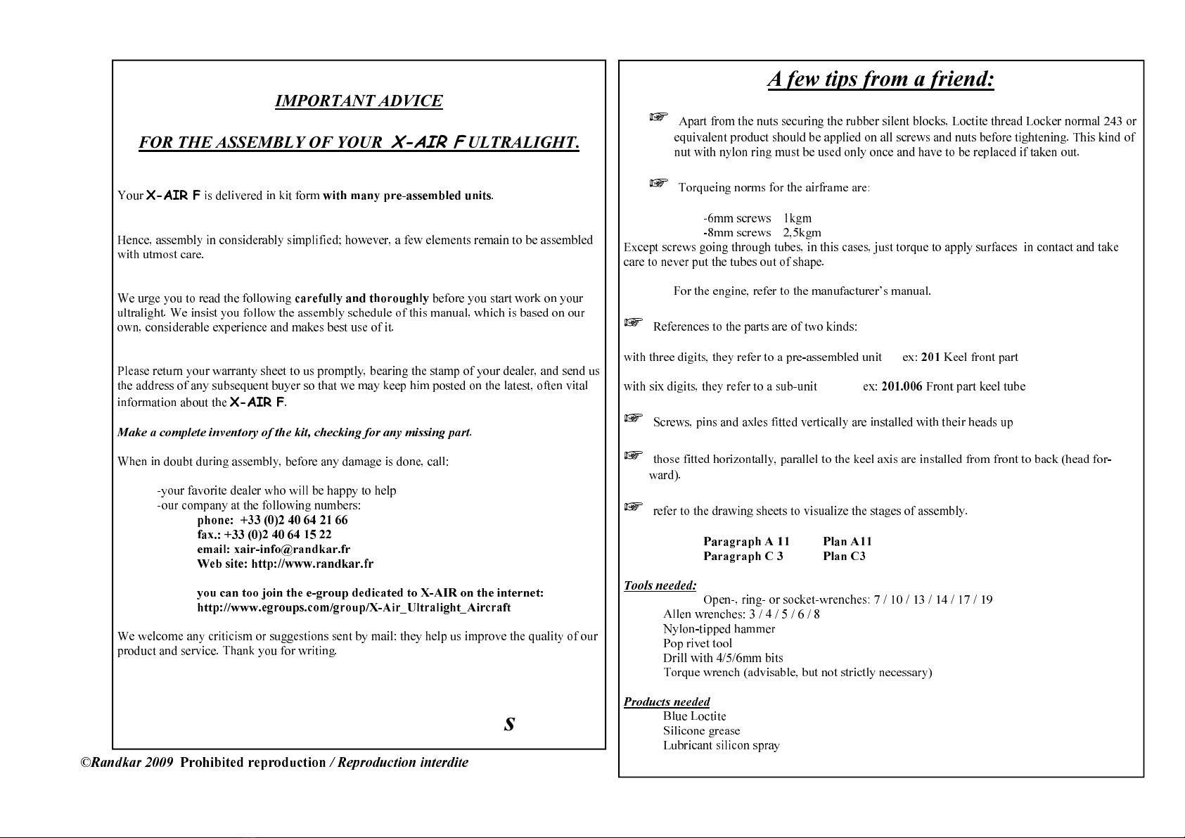
IMPORTANT AD ICE
FOR THE ASSEMBLY OF YOUR X-AIR F ULTRALIGHT.
Your
X-AIR F
is delivered in kit form
with many pre-assembled units
.
Hence, assembly in considerably simplified; however, a few elements remain to be assembled
with utmost care.
We urge you to read the following
carefully and thoroughly
before you start work on your
ultralight. We insist you follow the assembly schedule of this manual, which is based on our
own, considerable experience and makes best use of it.
Please return your warranty sheet to us promptly, bearing the stamp of your dealer, and send us
the address of any subse uent buyer so that we may keep him posted on the latest, often vital
information about the
X-AIR F
.
Make a complete inventory of the kit, checking for any missing part
.
When in doubt during assembly, before any damage is done, call:
-your favorite dealer who will be happy to help
-our company at the following numbers:
phone: +33 (0)2 40 64 2 66
fax.: +33 (0)2 40 64 5 22
email: xair-info@randkar.fr
Web site: http://www.randkar.fr
you can too join the e-group dedicated to X-AIR on the internet:
http://www.egroups.com/group/X-Air_Ultralight_Aircraft
We welcome any criticism or suggestions sent by mail: they help us improve the uality of our
product and service. Thank you for writing.
We wish you a pleasant, easy assembly,
and many enjoyable flights
A few tips from a friend:
Apart from the nuts securing the rubber silent blocks, Loctite thread Locker normal 243 or
e uivalent product should be applied on all screws and nuts before tightening. This kind of
nut with nylon ring must be used only once and have to be replaced if taken out.
Tor ueing norms for the airframe are:
-6mm screws 1kgm
-8mm screws 2,5kgm
Except screws going through tubes, in this cases, just tor ue to apply surfaces in contact and take
care to never put the tubes out of shape.
For the engine, refer to the manufacturer’s manual.
References to the parts are of two kinds:
with three digits, they refer to a pre-assembled unit ex:
20
Keel front part
with six digits, they refer to a sub-unit ex:
20 .006
Front part keel tube
Screws, pins and axles fitted vertically are installed with their heads up
those fitted horizontally, parallel to the keel axis are installed from front to back (head for-
ward).
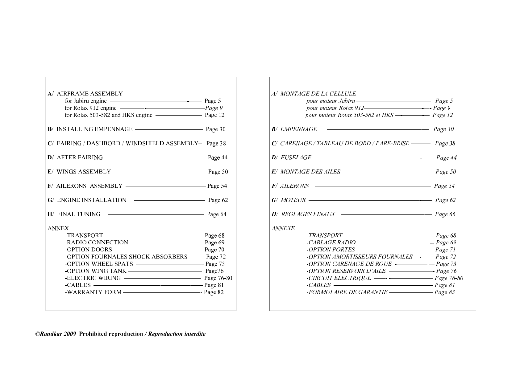
refer to the drawing sheets to visualize the stages of assembly.
Paragraph A Plan A
Paragraph C 3 Plan C3
Tools needed:
Open-, ring- or socket-wrenches: 7 / 10 / 13 / 14 / 17 / 19
Allen wrenches: 3 / 4 / 5 / 6 / 8
Nylon-tipped hammer
Pop rivet tool
Drill with 4/5/6mm bits
Tor ue wrench (advisable, but not strictly necessary)
Products needed
Blue Loctite
Silicone grease
Lubricant silicon spray