Rane DA216S User manual

DA216S
DISTRIBUTION AMPLIFIER
CONTENTS (in order of appearance)
Important Safety Instructions
DA216S Manual
DA216S Data Sheet
Sound System Interconnection
Rane Professional Install Products
Schematics
Warranty
Declaration of Conformity
22317

ATTENTION: RISQUE DE CHOCS ELECTRIQUE - NE PAS OUVRIR
RISK OF ELECTRIC SHOCK
DO NOT OPEN
CAUTION
To reduce the risk of electrical shock, do not open the unit. No user
serviceable parts inside. Refer servicing to qualied service personnel.
e symbols shown below are internationally accepted symbols
that warn of potential hazards with electrical products.
is symbol indicates that a dangerous voltage
constituting a risk of electric shock is present
within this unit.
is symbol indicates that there are important
operating and maintenance instructions in the
literature accompanying this unit.
WARNING
IMPORTANT SAFETY INSTRUCTIONS
1. Read these instructions.
2. Keep these instructions.
3. Heed all warnings.
4. Follow all instructions.
5. Do not use this apparatus near water.
6. Clean only with a dry cloth.
7. Do not block any ventilation openings. Install in accordance with manufacturer’s instructions.
8. Do not install near any heat sources such as radiators, registers, stoves, or other apparatus (including ampliers) that produce heat.
9. Do not defeat the safety purpose of the polarized or grounding-type plug. A polarized plug has two blades with one wider than the other. A
grounding-type plug has two blades and a third grounding prong. e wide blade or third prong is provided for your safety. If the provided plug
does not t into your outlet, consult an electrician for replacement of the obsolete outlet.
10. Protect the power cord and plug from being walked on or pinched particularly at plugs, convenience receptacles, and the point where it exits from
the apparatus.
11. Only use attachments and accessories specied by Rane.
12. Use only with the cart, stand, tripod, bracket, or table specied by the manufacturer, or sold with the apparatus. When a cart is used, use caution
when moving the cart/apparatus combination to avoid injury from tip-over.
13. Unplug this apparatus during lightning storms or when unused for long periods of time.
14. Refer all servicing to qualied service personnel. Servicing is required when the apparatus has been damaged in any way, such as power supply
cord or plug is damaged, liquid has been spilled or objects have fallen into the apparatus, the apparatus has been exposed to rain or moisture, does
not operate normally, or has been dropped.
15. e plug on the power cord is the AC mains disconnect device and must remain readily operable. To completely disconnect this apparatus from
the AC mains, disconnect the power supply cord plug from the AC receptacle.
16. is apparatus shall be connected to a mains socket outlet with a protective earthing connection.
17. When permanently connected, an all-pole mains switch with a contact separation of at least 3 mm in each pole shall be incorporated in the
electrical installation of the building.
18. If rackmounting, provide adequate ventilation. Equipment may be located above or below this apparatus, but some equipment (like large power
ampliers) may cause an unacceptable amount of hum or may generate too much heat and degrade the performance of this apparatus.
19. is apparatus may be installed in an industry standard equipment rack. Use screws through all mounting holes to provide the best support.
WARNING: To reduce the risk of re or electric shock, do not expose this apparatus to rain or moisture. Apparatus shall not be exposed to dripping
or splashing and no objects lled with liquids, such as vases, shall be placed on the apparatus.
NOTE: is equipment has been tested and found to comply with the limits for a Class B digital device, pursuant to part 15 of the FCC Rules.
ese limits are designed to provide reasonable protection against harmful interference in a residential installation. is equipment generates, uses
and can radiate radio frequency energy and, if not installed and used in accordance with the instructions, may cause harmful interference to radio
communications. However, there is no guarantee that interference will not occur in a particular installation. If this equipment does cause harmful
interference to radio or television reception, which can be determined by turning the equipment o and on, the user is encouraged to try to correct
the interference by one or more of the following measures:
• Reorient or relocate the receiving antenna.
• Increase the separation between the equipment and receiver.
• Connect the equipment into an outlet on a circuit dierent from that to which the receiver is connected.
• Consult the dealer or an experienced radio/TV technician for help.
CAUTION: Changes or modications not expressly approved by Rane Corporation could void the user's authority to operate the equipment.
CAN ICES-3 (B)/NMB-3(B)
WARNING: is product may contain chemicals known to the State of California to cause cancer, or birth defects or other reproductive harm.

ATTENTION: RISQUE DE CHOCS ELECTRIQUE - NE PAS OUVRIR
RISK OF ELECTRIC SHOCK
DO NOT OPEN
CAUTION
An d’éviter tout risque de choc électrique, ne pas ouvrir l’appareil.
Aucune pièce ne peut être changée par l’utilisateur. Contactez un
SAV qualié pour toute intervention.
Les symboles ci-dessous sont reconnus internationalement
comme prévenant tout risque électrique.
Ce symbole indique que cette unité utilise un
voltage élevé constituant un risque de choc
électrique.
Ce symbole indique la présence d’instructions
d’utilisation et de maintenance importantes dans le
document fourni.
ATTENTION
INSTRUCTIONS DE SÉCURITÉ
1. Lisez ces instructions.
2. Gardez précieusement ces instructions.
3. Respectez les avertissements.
4. Suivez toutes les instructions.
5. Ne pas utiliser près d’une source d’eau.
6. Ne nettoyer qu’avec un chion doux.
7. N’obstruer aucune évacuation d’air. Eectuez l’installation en suivant les instructions du fabricant.
8. Ne pas disposer près d’une source de chaleur, c-à-d tout appareil produisant de la chaleur sans exception.
9. Ne pas modier le cordon d’alimentation. Un cordon polarisé possède 2 lames, l’une plus large que l’autre. Un cordon avec tresse de masse possède
2 lames plus une 3è pour la terre. La lame large ou la tresse de masse assurent votre sécurité. Si le cordon fourni ne correspond pas à votre prise,
contactez votre électricien.
10. Faites en sorte que le cordon ne soit pas piétiné, ni au niveau du l, ni au niveau de ses broches, ni au niveau des connecteurs de vos appareils.
11. N’utilisez que des accessoires recommandés par Rane.
12. N’utilisez que les éléments de transport, stands, pieds ou tables spéciés par le fabricant ou vendu avec l’appareil. Quand vous utlisez une valise de
transport, prenez soin de vous déplacer avec cet équipement avec prudence an d’éviter tout risque de blessure.
13. Débranchez cet appareil pendant un orage ou si vous ne l’utilisez pas pendant un certain temps.
14. Adressez-vous à du personnel qualié pour tout service après vente. Celui-ci est nécessaire dans n’importe quel cas où l’appareil est abimé : si le
cordon ou les ches sont endommagés, si du liquide a été renversé ou si des objets sont tombés sur l’appareil, si celui-ci a été exposé à la pluie ou
l’humidité, s’il ne fonctionne pas correctement ou est tombé.
15. La che du cordon d’alimentation sert à brancher le courant alternatif AC et doit absolument rester accessible. Pour déconnecter totalement
l’appareil du secteur, débranchez le câble d’alimentation de la prise secteur.
16. Cet appareil doit être branché à une prise terre avec protection.
17. Quand il est branché de manière permanente, un disjoncteur tripolaire normalisé doit être incorporé dans l’installation électrique de l’immeuble.
18. En cas de montage en rack, laissez un espace susant pour la ventilation. Vous pouvez disposer d’autres appareils au-dessus ou en-dessous de celui-
ci, mais certains (tels que de gros amplicateurs) peuvent provoquer un buzz ou générer trop de chaleur au risque d’endommager votre appareil et
dégrader ses performances.
19. Cet appareil peut-être installé dans une baie standard ou un chassis normalisé pour un montage en rack. Visser chaque trou de chaque oreille de
rack pour une meilleure xation et sécurité.
ATTENTION: an d’éviter tout risque de feu ou de choc électrique, gardez cet appareil éloigné de toute source d’humidité et d’éclaboussures quelles
qu’elles soient. L’appareil doit également être éloigné de tout objet possédant du liquide (boisson en bouteilles, vases,…).
REMARQUE: Cet équipement a été testé et approuvé conforme aux limites pour un appareil numérique de classe B, conformément au chapitre 15
des règles de la FCC. Ces limites sont établis pour fournir une protection raisonnable contre tout risque d’interférences et peuvent provoquer une
énergie de radiofréquence s'il n'est pas installé et utilisé conformément aux instructions, peut également provoquer des interférences aux niveaux
des équipements de communication. Cependant, il n'existe aucune garantie que de telles interférences ne se produiront pas dans une installation
particulière. Si cet équipement provoque des interférences en réception radio ou télévision, ceci peut être detecté en mettant l'équipement sous/hors
tension, l'utilisateur est encouragé à essayer de corriger cette interférence par une ou plusieurs des mesures suivantes:
• Réorienter ou déplacer l'antenne de réception.
• Augmenter la distance entre l'équipement et le récepteur.
• Connecter l'équipement à une sortie sur un circuit diérent de celui sur lequel le récepteur est branché.
• Consulter un revendeur ou un technicien radio / TV expérimenté.
ATTENTION: Les changements ou modications non expressément approuvés par Rane Corporation peuvent annuler l'autorité de l'utilisateur à
manipuler cet équipement et rendre ainsi nulles toutes les conditions de garantie.
CAN ICES-3 (B)/NMB-3(B)
Cartons et papier à recycler.


Manual-1
DA216S
DISTRIBUTION AMPLIFIER
OPERATORS MANUAL
Quick Start
is section is for those that just can’t wait to get started. is
Distribution Amplier has a powerful feature not found on most
DA’s – Output assignment switches. If your application calls
for a single channel set-up with one Input driving all Outputs,
set all of the switches to the appropriate Input (Aor B). To mix
both inputs, set them all to A+B. In this mode, both Inputs drive
all Outputs with the Inputs summed. e MASTER LEVEL
controls set the input level. Occasionally blinking OL indicators
are okay. e individual OUTPUT LEVEL controls set the level
for each Output channel.
For a stereo application, decide how the stereo Outputs are to
be assigned and set the assignment switches accordingly. Eight
stereo outputs are possible.
Set the back panel switches for either LINE or MIC Inputs.
When using microphones that require a “phantom” voltage, turn
WEAR PARTS: is product contains no wear parts.
DA216S
DISTRIBUTION
AMPLIFIER
POWER
MASTER LEVELS
1
OUTPUT LEVELS
2
3
4
5
6
7
8
9
10
11
12
13
14
15
16
A
B
on the PHANTOM POWER switch, illuminating its rear panel
LED. Because the phantom voltage is applied to both Inputs,
don’t mix phantom powered and non-phantom powered mics in
the same DA216S. Never engage the phantom voltage when using
an unbalanced mic—doing so may damage the mic. If the mic is
too “hot”, press the INPUT GAIN switch in to reduce the gain
by 20 dB. Incidentally, the INPUT PAD switch reduces the gain
40 dB when in the LINE position (pressed in). When using the
Inputs for line-level, pressing in both the INPUT PAD and the
INPUT GAIN switches provides a nominal gain of 0 dB. An
additional 16 dB of gain is available when both the MASTER
LEVEL and OUTPUT LEVEL controls are turned all the way
up (clockwise).
e internal universal supply allows operation in almost any
part of the world. All that is required in dierent countries is the
correct IEC line cord.

Manual-2
DA216S Front Panel
1 MASTER LEVELS: ese screwdriver adjustable controls set the level of each Input to be routed to bus A, B, or A+B.
e Overload (OL) LEDs illuminate whenever either Input section (both pre-gain and post-gain) approach clipping.
Each MASTER LEVEL may be adjusted from o to +10 dB gain.
2 OUTPUT LEVEL controls: Each Output channel has an independent LEVEL control.
Each Output may be adjusted from o to +6 dB gain.
3 Output Assign switches: Each switch has three positions, which assign the Output to the A-Input, the B-Input, or A+B (sum).
is powerful feature allows the DA216S distribution amplier to be set up as 1 Input to 16 Outputs.
Or 1 stereo Input pair to 8 stereo Output pairs. Or 1 Input to 3 Outputs, with the other Input to 13 Outputs. And so on.
For those of you that like impressive numbers, that amounts to 43,046,721 possible combinations (316)! Go ahead – count
them. By the way, for those that really like this stu, if we allow turning the gain all the way down on any Output as part of the
combination, the number jumps to 4,294,967,295 (416). Fortunately, most users will only be concerned with one or two of these
possibilities.
4 POWER Indicator: When this yellow LED is illuminated power is running through the DA216S.
3 4
1 2
DA216S
DISTRIBUTION
AMPLIFIER
POWER
MASTER LEVELS
1
OUTPUT LEVELS
2
3
4
5
6
7
8
9
10
11
12
13
14
15
16
A
B

Manual-3
DA216S Rear Panel
1 INPUT Euroblocks: Attach either Microphone or Line-level sources here. Euroblocks accept any #14 to #26 guage wire.
Connect balanced sources to the respective “+” and “–”terminals, and tie the shield to chassis ground.
For unbalanced sources use two-conductor shielded cable as described in DA216S Connection on page Manual-4.
2 Output Euroblocks 1-16: Balanced Outputs are provided for each of 16 channels.
Connect two conductor shielded cable to “+” and “–” terminals, and connect the shield to the ground terminal.
For unbalanced use, do not connect “–” to chassis ground. See the Outputs section on page Manual-4.
3 INPUT PAD switches: In the MIC position (out), the gain is appropriate for a microphone Input (40 dB or 60 dB). In the LINE
position (in), the gain is line-level (0 dB or 20 dB). When this switch is in the LINE position, PHANTOM POWER (5) for the
channel is disabled.
4 INPUT GAIN switches: Changes the gain by 20 dB. at is, with mic Input, the INPUT GAIN switch sets the gain to 60 dB
(out) or 40 dB (in). With a line-level Input, it sets the gain to 20 dB (out) or 0 dB (in).
5 PHANTOM POWER switch: When activated (in), 15 VDC Phantom Power appears at each mic-level Input and the LED
illuminates. If an Input is selected for line-level, the Phantom Voltage is disabled for that channel, even when the PHANTOM
LED is lit.
6 Power connector: e internal universal switching power supply operates on any AC mains 100 to 240 VAC, 50 or 60 Hz (most
places in the world). All that is required when traveling is the appropriate IEC line cord.
INPUT
B
MIC
MIC
PAD
PAD
GAIN
GAIN
INPUT
A
40
60
dB
0
MIC
PHANTOM
POWER
15V
20
40
60
dB
0
20
LINE
LINE
INPUT
A
INPUT
B
4
3
2
1
-
+
-
+
-
+
-
+
-
+
-
+
8
7
6
5
-
+
-
+
-
+
-
+
12
11
10
9
-
+
-
+
-
+
-
+
16
15
14
13
-
+
-
+
-
+
-
+
-
+
-
+
100-240 V
50/60 Hz 7 WATTS
ALL AUDIO JACKS ARE CLASS 2 WIRING
DA216S
RANE CORPORATION
COMMERCIAL AUDIO
EQUIPMENT 24TJ
R
6 5431
2

Manual-4
©Rane Corporation 10802 47th Ave. W., Mukilteo WA 98275-5000 USA TEL 425-355-6000 FAX 425-347-7757 WEB rane.com
Operating Instructions
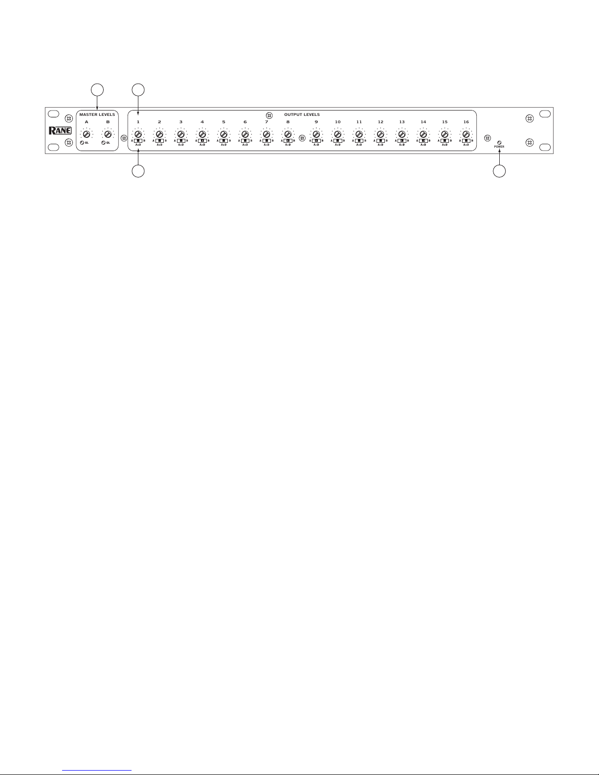
Using the 3-position Output Assign switches, select either the
A Input, the B Input, or A+B Inputs. If the sum of both Inputs is
selected, but only one Input is driven, the Output is reduced by
6 dB compared to the Output being assigned to only the driven
Input. Since normally the Output would be assigned to both
Inputs only if both Inputs are driven, this isn’t usually an issue.
With the sum of the Inputs available in this way, the DA216S
may be used as a two-input mixer with 16 assignable Outputs.
Each Output has an independent Gain control which ranges
from o to +6 dB gain in the output stage. Coupled with a maxi-
mum gain of +10 dB for the MASTER LEVEL controls, a total
of +16 dB gain is available with the OUTPUT LEVEL controls.
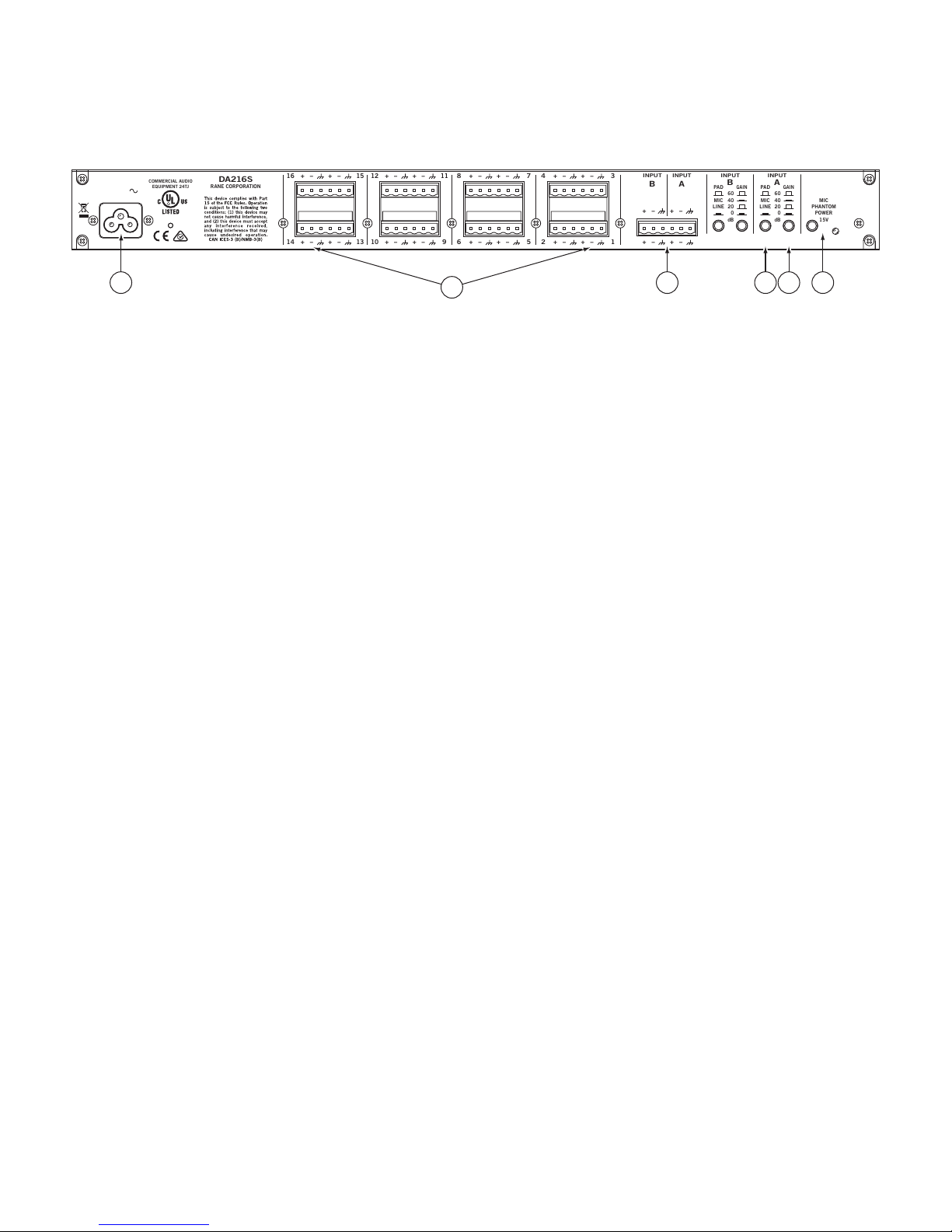
e INPUT GAIN switch provides for an additional 20 dB gain
increase.
MIC-LEVEL
For optimum noise performance with microphones, obtain as
much gain as possible in the Input stage of the DA216S without
overdriving the unit.
1. Set the appropriate INPUT PAD switch to MIC (out).
2. Set the appropriate INPUT GAIN switch to 40 dB (in).
3. Set the MASTER LEVEL controls fully counterclockwise.
4. Set the OUTPUT LEVEL controls midway.
5. Adjust the MASTER LEVEL clockwise until the OL
LED just blinks on the loudest expected program material. If
the MASTER LEVEL is turned all the way up and the OL LED
is not lighting, set the INPUT GAIN to 60 dB and adjust the
MASTER LEVEL again. Adjust the OUTPUT LEVELs for
the desired output level. If the OL LED is not lit, adjusting the
OUTPUT LEVEL cannot cause clipping within the DA216S.
e user may still want to turn down the OUTPUT LEVEL to
avoid overloading downstream equipment.
LINE-LEVEL
In the LINE-level conguration, start with unity gain.
1. Set INPUT PAD switch to LINE position (in).
2. Set appropriate INPUT GAIN switch to 0 dB.
3. Set MASTER LEVEL controls fully counterclockwise.
4. Set OUTPUT LEVEL controls midway.
5. Adjust the MASTER LEVEL clockwise until the OL
LED just blinks on the loudest expected program material. If
the MASTER LEVEL is turned all the way up and the OL LED
never comes on, set the INPUT GAIN switch out to the 20 dB
position. Adjust the MASTER LEVEL control as before for
optimum gain, then adjust the OUTPUT LEVEL controls for
the desired output level.
DA216S Connection
When connecting the DA216S to other components in your
system, leave the power supply for last. is gives you a chance to
make mistakes and correct them without announcing what you
did to the whole world and without damaging “downstream”
equipment. Remember this when setting INPUT PAD, INPUT
GAIN and PHANTOM POWER switches. ese switches
should never be changed in a live system. Suddenly changing
the gain by 40 dB can have a profound impact on the ears of the
listening audience.
INPUTS
e two Inputs on the DA216S are balanced. ey may also be
used in an unbalanced conguration. However, if used unbal-
anced, do not engage Phantom Power. Use only shielded cable
for the Inputs. is cable should always be two conductors plus
shield, even for unbalanced operation. If you must use shielded
single conductor, keep the cable as short as possible (under 10
feet [3 meters]) to avoid hum or radio pick up.
When connecting Inputs, use all three Input terminals. For
unbalanced, the “hot” Input goes to the “+”, and the common
wire goes to the “–” while the shield connects the ground. Since
the common wire and shield are to be tied together at one end
in an unbalanced system, this connects the “–” Input to chassis
ground. In a balanced system (highly preferred), the “+” Input
connects to the “+” Output of the previous equipment. e “–”
Input then connects to the “–” Output and the shield goes to the
chassis ground. ese Input connections may be reversed if it is
necessary to reverse the polarity of the Input signal.
Be aware, if a microphone is used which requires Phantom
Power, the shield must be connected to chassis ground to complete the
Phantom Power circuit. Remember, a dynamic mic will likely be
damaged if used unbalanced while the Phantom Power is turned
on. At the very least, it will saturate the mic’s output transformer
and spoil the sound quality. With the INPUT PAD switched to
LINE, Phantom Power is disabled for that Input only. at is, a
balanced, Phantom Powered mic may be used at one Input and a
line input at the other without problems.
See the RaneNote “Sound System Interconnection” for ad-
ditional information on grounding and shielding.
OUTPUTS
e DA216S’s Outputs are balanced and quite substantial. ey
will easily drive long cables and 600 Ω loads to full level. e
same wiring conventions as the Inputs apply. For unbalanced
Outputs, “hot” goes to the “+”, and the shield connects to chassis
ground. When wiring unbalanced Outputs, do not tie the un-
used terminal (normally “–”) to Ground — leave it oating.
32 Unbalanced Outputs Tip: e (“–”) Output may also be
used as an unbalanced line driver, albeit inverted. e balanced In-
put terminals of the next stage must be reversed (+) for (–) to correct
for the inversion. is nets a total of 32 Outputs!
106334

DA216S
DISTRIBUTION AMPLIFIER
Data Sheet-1
General Description
e Rane DA216S Distribution Amplier is a two-input, sixteen-
output splitter/distribution amplier. e DA216S is capable
of providing sixteen discrete balanced outputs from one or two
balanced mic-level or line-level inputs. e level of each output
is individually adjusted via one of the sixteen screwdriver Output
Level controls on the front panel. Each output may be assigned to
either or both inputs via front panel accessible slide switches.
e Master A and B Level controls aect the overall level of
each input. In other words, they allow all assigned outputs to be
turned up or down at once. LEDs indicate an Overload (OL) at
either the inputs or at the internal gain stages.
Each input is set to either Mic or Line level via the rear panel
Input Pad pushbutton. e separate Input Gain pushbutton
switches provide a microphone input with +60 or +40 dB of gain,
or a line input with +20 or 0 dB of gain. With Input Gain, Mas-
ter Levels and Output Levels, any reasonable input signal may be
adjusted to a nominal +4 dBu and still have 17 dB of headroom.
e Phantom Power switch provides +15 VDC for condenser
microphones. Any input assigned to line-level has this phantom
voltage turned o automatically. A rear-panel LED indicates when
the Phantom Power is engaged.
Each output stage incorporates a high-current balanced out-
put line driver for driving long lines with optimal performance.
e DA216S improves on the previous DA 216 model with
an internal universal voltage power supply, operable nearly any-
where in the world (100-240 VAC).
Features
• A, B, A&B Output Assign Switches
• Sixteen Balanced (Terminal) Outputs, Individually Assignable
• Two Balanced Inputs
• Studio Grade Low Noise Input Amp
• Input Overload Indicators
• Mic/Line Input Switches
• Gain Switches: 40/60 dB Mic, 0/20 dB Line
• Phantom Power Switch
• Master Input and Individual Output Level Controls
• Stable High-Current Line Drivers
• All Outputs Capable of Driving 600Ω Loads Simultaneously
• UL/CSA/CE Internal Universal Power Supply (100-240 VAC)
DATA SHEET

DA216S
DISTRIBUTION AMPLIFIER
Data Sheet-2
Features and Specifications
Parameter Specication Limit Units Conditions/Comments
Mic Input Impedance 1.82k 1% Balanced 909 + 909
Line Input Impedance 17.9k 1% Balanced 8.97k + 8.97k
Mic Gain Control +40 & +60 ±2 dB 2-position switch
Mic Pad 20 ±2 dB 2-position switch
Line Gain Range 0 & +20 ±2 dB 2-position switch
Overall Mic Gain +56 & +76 ±4 dB All controls maximum
Overall Line Gain +16 & +36 ±4 dB All controls maximum
Max Mic Input Level -20 typ dBu Gain at 40 dB
Max Line Input Level +21 typ dBu Gain at 0 dB
Overload LED 3 dB below clip typ Clip dened as 1% THD+N
Phantom Power +15 ±0.5 VDC Phantom Power switch active
Output Impedance 200 1% Balanced 100+100
Output Drive Level +24 typ dBu 600 load
Output Cable Length 1500 max feet Belden 8451 or equivalent
Mic Equivalent Input Noise -128 typ dBu Rs=150, gain=60 dB
Line Signal-To-Noise Ratio 100 min dBV gain=0 dB, re +4 dBu, 22 kHz BW
THD+Noise (Line Input) 0.005 typ % gain=0 dB, +4 dBu@1 kHz, 80 kHz BW
Frequency Response, Line 15-50 k Hz +0, –3 dB 0 dB Gain, 0 dBu Output
Frequency Response, Mic 15-50 k Hz +0, –3 dB 40 dB Gain, 0 dBu Output
Frequency Response, Mic 30-50 kHz +0, –3 dB 60 dB Gain, 0 dBu Output
Crosstalk 80 typ dB +4 dBu Output, 1 kHz
Power Supply Requirement 100 to 240 10% VAC 50/60 Hz, 7W
Unit: Conformity CE, FCC, UL
Unit: Construction All Steel
..........Size 1.75"H x 19"W x 5.3"D (1U) (4.4 cm x 48.3 cm x 13.3 cm)
..........Weight 4 lb (1.9 kg)
Shipping: Size 4.25" x 20.3" x 13.75" (11 cm x 52 cm x 35 cm)
..........Weight 7 lb (3.2 kg)
Note: 0 dBu=0.775 Vrms

DA216S
DISTRIBUTION AMPLIFIER
Data Sheet-3
Applications
Use of the DA216S is straightforward. Connect balanced inputs
and outputs to the Euroblocks, following the silk-screened labels.
Wire range is #14 to #26 stranded or solid.
e diagram above shows the uncomplicated nature. Fully
balanced low-noise mic preampliers receive the signal to be split
or distributed. e Input Pad pushbuttons change the input gain
range. Additional Gain pushbuttons increase either Mic or Line
level inputs another +20 dB (see table above).
Keep an eye on the Overload indicators when setting the gain.
Always use the most gain possible without causing the Overload
indicator to light. Occasional ickering is permitted. Setting
gain this way maintains the best signal-to-noise performance for
the system. e Master Level controls allow level matching and
balancing as required.
When operating unbalanced, a 6 dB loss of signal must be
taken into account when setting the gain structure of the system.
When wiring an Output for unbalanced operation do not ground the
unused terminal (i.e. usually the “–”). Unbalanced uses only the “+”
and ground terminals.
Block Diagram
+10 dB
+10 dB
POWER
PHANTOM
INPUT
PROTECT
RFI/EMI 20 dB
PAD
ESD
OL
INPUT
PROTECT
RFI/EMI
ESD
OL
INPUT A
INPUT B
15V
GAIN
20 dB
PAD
MIC/LINE
PADINPUT
INPUT
LEVEL B
MASTER
GAIN
MIC/LINE
PADINPUT
INPUT
LEVEL A
MASTER
A
A+B
B
SELECT OUTPUT
LEVEL
+6 dB
+6 dB
+6 dB
+6 dB
OUTPUT 1
OUTPUT 2
OUTPUT 3
OUTPUT 4
+
_
+
_
+
_
+
_
TO OUTPUTS 5 - 16
+
–
+
–
INPUT PAD GAINNET GAIN
IN
OUT
IN
OUT
20 dB
40 dB
40 dB
60 dB
0 dB
+20 dB
+40 dB
+60 dB
-20 dB
IN
(LINE)
OUT
(MIC) 0 dB
INPUT A
EACH
OUTPUT
SELECTS
A, B or BOTH
INPUT B
DA216S
PROGRAM
SOURCE
CD, DVD, SAT
PAGE MIC
(MIC OR LINE)
(MIC OR LINE)
ZONE 1 AMP
OUTPUT 1
ZONE 2 AMP
OUTPUT 2
ZONE 3 AMP
OUTPUT 3
ZONE 4 AMP
OUTPUT 4
ZONE 5 AMP
OUTPUT 5
ZONE 6 AMP
OUTPUT 6
ZONE 7 AMP
OUTPUT 7
ZONE 8 AMP
OUTPUT 8
ZONE 9 AMP
OUTPUT 9
ZONE 10 AMP
OUTPUT 10
ZONE 11 AMP
OUTPUT 11
ZONE 12 AMP
OUTPUT 12
ZONE 13 AMP
OUTPUT 13
ZONE 14 AMP
OUTPUT 14
ZONE 15 AMP
OUTPUT 15
ZONE 16 AMP
OUTPUT 16
PAGE
&
MUSIC
PAGE
ONLY
MUSIC
ONLY
Application Example

DA216S
DISTRIBUTION AMPLIFIER
Data Sheet-4 All features & specications subject to change without notice. 9-2015
©Rane Corporation 10802 47th Ave. W., Mukilteo WA 98275-5000 TEL 425-355-6000 FAX 425-347-7757 WEB rane.com
Rear Panel
Architectural Specifications
e distribution amplier shall have two (2) inputs and six-
teen (16) outputs. e unit shall be capable of mono (16 mono
outputs) or stereo operation (8 stereo outputs) via front panel
switches. Each output shall be assignable to either or both of the
master inputs.
Each input shall be microphone or line level switchable by
means of rear panel switches. Additional 20 dB gain switches shall
be built-in for each input, applicable to either a mic or line level
signal. Each input shall have a front panel screwdriver level ad-
justment. 15V phantom power shall be provided via a rear panel
switch for microphone inputs.
Each output shall have a front panel screwdriver adjustment.
Inputs and outputs shall be active balanced screw terminal con-
nectors.
e unit shall be capable of operation by means of its own
built-in universal power supply operating at 100-240 VAC and
meet CE requirements. e unit shall be UL and cUL listed. e
unit shall be entirely constructed from cold-rolled steel.
e unit shall be a Rane DA216S Distribution Amplier.
32 Unbalanced Outputs
e (“–”) Output may also be used as an unbalanced line driver,
albeit inverted. e balanced Input terminals of the next stage
must be reversed (+) for (–) to correct for the inversion. is nets
a total of 32 Outputs! However, the penalty for 32 outputs is that
unbalanced operation will not drive long lines and individual
control is lost.

Interconnection-1
Introduction
is note, originally written in 1985, continues to be one
of our most useful references. It’s popularity stems from
the continual and perpetual difficulty of hooking up audio
equipment without suffering through all sorts of bizarre
noises, hums, buzzes, whistles, etc.— not to mention the
extreme financial, physical and psychological price. As tech-
nology progresses it is inevitable that electronic equipment
and its wiring should be subject to constant improvement.
Many things have improved in the audio industry since
1985, but unfortunately wiring isn’t one of them. However,
finally the Audio Engineering Society (AES) has issued a
standards document for interconnection of pro audio equip-
ment. It is AES48, titled “AES48-2005: AES standard on
interconnections —Grounding and EMC practices — Shields
of connectors in audio equipment containing active circuitry.”
Rane’s policy is to accommodate rather than dictate.
However, this document contains suggestions for external
wiring changes that should ideally only be implemented by
trained technical personnel. Safety regulations require that
all original grounding means provided from the factory be
left intact for safe operation. No guarantee of responsibility
for incidental or consequential damages can be provided. (In
other words, don’t modify cables, or try your own version of
grounding unless you really understand exactly what type of
output and input you have to connect.)
Rane Technical Staff
RaneNote 110
© 1985, 1995, 2006, 2007, 2011, 2015 Rane Corporation
Sound System
Interconnection
• Cause & prevention of ground loops
• Interfacing balanced & unbalanced
• Proper pin connections and wiring
• Chassis ground vs. signal ground
• Ground lift switches
RaneNote
SOUND SYSTEM INTERCONNECTION

Interconnection-2
Ground Loops
Almost all cases of noise can be traced directly to ground
loops, grounding or lack thereof. It is important to under-
stand the mechanism that causes grounding noise in order
to effectively eliminate it. Each component of a sound
system produces its own ground internally. is ground is
usually called the audio signal ground. Connecting devices
together with the interconnecting cables can tie the signal
grounds of the two units together in one place through
the conductors in the cable. Ground loops occur when the
grounds of the two units are also tied together in another
place: via the third wire in the line cord, by tying the metal
chassis together through the rack rails, etc. ese situations
create a circuit through which current may flow in a closed
“loop” from one unit’s ground out to a second unit and back
to the first. It is not simply the presence of this current that
creates the hum—it is when this current flows through a
unit’s audio signal ground that creates the hum. In fact, even
without a ground loop, a little noise current always flows
through every interconnecting cable (i.e., it is impossible to
eliminate these currents entirely). e mere presence of this
ground loop current is no cause for alarm if your system
uses properly implemented and completely balanced inter-
connects, which are excellent at rejecting ground loop and
other noise currents. Balanced interconnect was developed
to be immune to these noise currents, which can never be
entirely eliminated. What makes a ground loop current an-
noying is when the audio signal is affected. Unfortunately,
many manufacturers of balanced audio equipment design
the internal grounding system improperly, thus creating bal-
anced equipment that is not immune to the cabling’s noise
currents. is is one reason for the bad reputation some-
times given to balanced interconnect.
A second reason for balanced interconnect’s bad reputa-
tion comes from those who think connecting unbalanced
equipment into “superior” balanced equipment should
improve things. Sorry. Balanced interconnect is not compat-
ible with unbalanced. e small physical nature and short
cable runs of completely unbalanced systems (home audio)
also contain these ground loop noise currents. However, the
currents in unbalanced systems never get large enough to
affect the audio to the point where it is a nuisance. Mixing
balanced and unbalanced equipment, however, is an entirely
different story, since balanced and unbalanced interconnect
are truly not compatible. e rest of this note shows several
recommended implementations for all of these interconnec-
tion schemes.
e potential or voltage which pushes these noise cur-
rents through the circuit is developed between the indepen-
dent grounds of the two or more units in the system. e
impedance of this circuit is low, and even though the voltage
is low, the current is high, thanks to Mr. Ohm, without
whose help we wouldn’t have these problems. It would take
a very high resolution ohm meter to measure the impedance
of the steel chassis or the rack rails. We’re talking thou-
sandths of an ohm. So trying to measure this stuff won’t
necessarily help you. We just thought we’d warn you.
The Absolute Best Right Way To Do It
e method specified by AES48 is to use balanced lines and
tie the cable shield to the metal chassis (right where it enters
the chassis) at both ends of the cable.
A balanced line requires three separate conductors, two
of which are signal (+ and –) and one shield (see Figure 1a).
e shield serves to guard the sensitive audio lines from
interference. Only by using balanced line interconnects can
you guarantee (yes, guarantee) hum-free results. Always use
twisted pair cable. Chassis tying the shield at each end also
guarantees the best possible protection from RFI [radio fre-
quency interference] and other noises [neon signs, lighting
dimmers].
Neil Muncy1, an electroacoustic consultant and seasoned
veteran of years of successful system design, chairs the AES
Figure 1a. The right way to do it.
+
–
G
T
R
S
RED
BLACK 2-CONDUCTOR SHIELDED CABLE
2-CONDUCTOR SHIELDED CABLE
SHIELD
RED
BLACK
SHIELD
RED
BLACK
SHIELD
RED
BLACK
SHIELD
RED
BLACK
SHIELD
RED
BLACK
SHIELD
CHASSIS
GROUND CHASSIS
GROUND SIGNAL
GROUND
S
R
T
G
–
+
BALANCED OUTPUTS BALANCED INPUTS
MALE FEMALEMALE FEMALE
1
2
3
C
1
3
2 2
C3
1
2
1
3

Interconnection-3
Standards Committee (SC-05-05) working on this subject.
He tirelessly tours the world giving seminars and dispens-
ing information on how to successfully hook-up pro audio
equipment2. He makes the simple point that it is absurd that
you cannot go out and buy pro audio equipment from sever-
al different manufacturers, buy standard off-the-shelf cable
assemblies, come home, hook it all up and have it work hum
and noise free. Plug and play. Sadly, almost never is this the
case, despite the science and rules of noise-free interconnect
known and documented for over 60 years (see References for
complete information).
It all boils down to using balanced lines, only balanced
lines, and nothing but balanced lines. is is why they were
developed. Further, that you tie the shield to the chassis, at
the point it enters the chassis, and at both ends of the cable
(more on ‘both ends’ later).
Since standard XLR cables come with their shields tied to
pin 1 at each end (the shells are not tied, nor need be), this
means equipment using 3-pin, XLR-type connectors must
tie pin 1 to the chassis (usually called chassis ground) — not
the audio signal ground as is most common.
Not using signal ground is the most radical departure
from common pro-audio practice. Not that there is any ar-
gument about its validity. ere isn’t. is is the right way
to do it. So why doesn’t audio equipment come wired this
way? Well, some does, and since 1993, more of it does. at’s
when Rane started manufacturing some of its products with
balanced inputs and outputs tying pin 1 to chassis. So why
doesn’t everyone do it this way? Because life is messy, some
things are hard to change, and there will always be equip-
ment in use that was made before proper grounding prac-
tices were in effect.
Unbalanced equipment is another problem: it is ever-
where, easily available and inexpensive. All those RCA and
¼" TS connectors found on consumer equipment; effect-
loops and insert-points on consoles; signal processing boxes;
semi-pro digital and analog tape recorders; computer cards;
mixing consoles; et cetera.
e next several pages give tips on how to successfully
address hooking up unbalanced equipment. Unbalanced
equipment when “blindly” connected with fully balanced
units starts a pattern of hum and undesirable operation,
requiring extra measures to correct the situation.
Figure 1b. Recommmended practice.
CASE
(+)
(–)
COMMON (WRONG) PRACTICE RECOMMENDED PRACTICE
(–)
(+)
OPTIONAL
CASE
1
2
33
1
2
CHASSIS
GROUND SIGNAL
GROUND CHASSIS
GROUND CHASSIS
GROUND
The Next Best Right Way To Do It
e quickest, quietest and most foolproof method to con-
nect balanced and unbalanced is to transformer isolate all
unbalanced connections. See Figure 2.
Many manufacturers provide several tools for this task,
including Rane. Consult your audio dealer to explore the
options available.
e goal of these adaptors is to allow the use of standard
cables. With these transformer isolation boxes, modification
of cable assemblies is unnecessary. Virtually any two pieces
of audio equipment can be successfully interfaced without
risk of unwanted hum and noise.
Another way to create the necessary isolation is to use a
direct box. Originally named for its use to convert the high
impedance, high level output of an electric guitar to the low
impedance, low level input of a recording console, it allowed
the player to plug “directly” into the console. Now this term
is commonly used to describe any box used to convert un-
balanced lines to balanced lines.
The Last Best Right Way To Do It
If transformer isolation is not an option, special cable
assemblies are a last resort. e key here is to prevent the
shield currents from flowing into a unit whose grounding
scheme creates ground loops (hum) in the audio path (i.e.,
most audio equipment).
It is true that connecting both ends of the shield is theo-
retically the best way to interconnect equipment –though
this assumes the interconnected equipment is internally
grounded properly. Since most equipment is not internally
grounded properly, connecting both ends of the shield is
not often practiced, since doing so usually creates noisy
interconnections.
A common solution to these noisy hum and buzz prob-
lems involves disconnecting one end of the shield, even
though one can not buy off-the-shelf cables with the shield
disconnected at one end. e best end to disconnect is the
receiving end. If one end of the shield is disconnected, the
noisy hum current stops flowing and away goes the hum
— but only at low frequencies. A ground-sending-end-only
shield connection minimizes the possibility of high fre-
quency (radio) interference since it prevents the shield from
acting as an antenna to the next input. Many reduce this
potential RF interference by providing an RF path through
Figure 2. Transformer Isolation
NOT CONNECTED
AT CHASSIS
(PLASTIC JACK)
EARTH GROUNDED
METAL ENCLOSURE
CHASSIS IS
GROUNDED TO PIN 1
1/4”
TIP-SLEEVE
CASE LUG MAY
CONNECT TO
CHASSIS
(NOT REQUIRED)
TRANSFORMER
UNBALANCED BALANCED
3
1
2

Interconnection-4
a small capacitor (0.1 or 0.01 microfarad ceramic disc) con-
nected from the lifted end of the shield to the chassis. (is
is referred to as the “hybrid shield termination” where the
sending end is bonded to the chassis and the receiving end is
capacitively coupled. See Neutrik’s EMC-XLR for example.)
e fact that many modern day installers still follow this
one-end-only rule with consistent success indicates this
and other acceptable solutions to RF issues exist, though
the increasing use of digital and wireless technology greatly
increases the possibility of future RF problems.
If you’ve truly isolated your hum problem to a specific
unit, chances are, even though the documentation indicates
proper chassis grounded shields, the suspect unit is not in-
ternally grounded properly. Here is where special test cable
assemblies, shown in Figure 3, really come in handy. ese
assemblies allow you to connect the shield to chassis ground
at the point of entry, or to pin 1, or to lift one end of the
shield. e task becomes more difficult when the unit you’ve
isolated has multiple inputs and outputs. On a suspect unit
with multiple cables, try various configurations on each con-
nection to find out if special cable assemblies are needed at
more than one point.
See Figure 4 for suggested cable assemblies for your par-
ticular interconnection needs. Find the appropriate output
configuration (down the left side) and then match this with
the correct input configuration (across the top of the page.)
en refer to the following pages for a recommended wiring
diagram.
Ground Lifts
Many units come equipped with ground lift switches. In
only a few cases can it be shown that a ground lift switch
improves ground related noise. (Has a ground lift switch
ever really worked for you?) In reality, the presence of a
ground lift switch greatly reduces a unit’s ability to be
“properly” grounded and therefore immune to ground loop
hums and buzzes. Ground lifts are simply another Band-Aid®
to try in case of grounding problems. It is true that an entire
system of properly grounded equipment, without ground
lift switches, is guaranteed (yes guaranteed) to be hum free.
e problem is most equipment is not (both internally and
externally, AC system wise) grounded properly.
Most units with ground lifts are shipped so the unit is
“grounded” — meaning the chassis is connected to audio
signal ground. (is should be the best and is the “safest”
position for a ground lift switch.) If after hooking up your
system it exhibits excessive hum or buzzing, there is an
incompatibility somewhere in the system’s grounding con-
figuration. In addition to these special cable assemblies that
may help, here are some more things to try:
1. Try combinations of lifting grounds on units supplied
with lift switches (or links). It is wise to do this with the
power off!
2. If you have an entirely balanced system, verify all chassis
are tied to a good earth ground, for safety’s sake and hum
protection. Completely unbalanced systems never earth
ground anything (except cable TV, often a ground loop
source). If you have a mixed balanced and unbalanced
system, do yourself a favor and use isolation transform-
ers or, if you can’t do that, try the special cable assemblies
described here and expect it to take many hours to get
things quiet. May the Force be with you.
3. Balanced units with outboard power supplies (wall warts
or “bumps” in the line cord) do not ground the chassis
through the line cord. Make sure such units are solidly
grounded by tying the chassis to an earth ground using a
star washer for a reliable contact. (Rane always provides
this chassis point as an external screw with a toothed
washer.) Any device with a 3-prong AC plug, such as an
amplifier, may serve as an earth ground point. Rack rails
may or may not serve this purpose depending on screw
locations and paint jobs.
Figure 3. Test cable
TEST
WIRE
GROUND CLIP
FEMALE MALE
1
C
2
3
1
2
3
RED
BLACK
SHIELD
RED
BLACK
SHIELD
2-CONDUCTOR SHIELDED CABLE

Interconnection-5
Floating, Pseudo, and Quasi-Balancing
During inspection, you may run across a ¼" output called
floating unbalanced, sometimes also called psuedo-balanced
or quasi-balanced. In this configuration, the sleeve of the
output stage is not connected inside the unit and the ring
is connected (usually through a small resistor) to the audio
signal ground. is allows the tip and ring to “appear” as
an equal impedance, not-quite balanced output stage, even
though the output circuitry is unbalanced.
Floating unbalanced often works to drive either a bal-
anced or unbalanced input, depending if a TS or TRS stan-
dard cable is plugged into it. When it hums, a special cable
is required. See drawings #11 and #12, and do not make
the cross-coupled modification of tying the ring and sleeve
together.
Winning the Wiring Wars
• Use balanced connections whenever possible, with the
shield bonded to the metal chassis at both ends.
• Transformer isolate all unbalanced connections from bal-
anced connections.
• Use special cable assemblies when unbalanced lines can-
not be transformer isolated.
• Any unbalanced cable must be kept under 10 feet
(3 m) in length. Lengths longer than this will amplify all
the nasty side effects of unbalanced circuitry's ground
loops.
Summary
If you are unable to do things correctly (i.e. use fully bal-
anced wiring with shields tied to the chassis at both ends,
or transformer isolate all unbalanced signals from balanced
signals) then there is no guarantee that a hum-free intercon-
nect can be achieved, nor is there a definite scheme that will
assure noise-free operation in all configurations.
References
1. Neil A. Muncy, “Noise Susceptibility in Analog and Digi-
tal Signal Processing Systems,” presented at the 97th AES
Convention of Audio Engineering Society in San Fran-
cisco, CA, Nov. 1994.
2. Grounding, Shielding, and Interconnections in Analog
& Digital Signal Processing Systems: Understanding the
Basics; Workshops designed and presented by Neil Muncy
and Cal Perkins, at the 97th AES Convention of Audio
Engineering Society in San Francisco, CA, Nov. 1994.
3. e entire June 1995 AES Journal, Vol. 43, No. 6, available
$6 members, $11 nonmembers from the Audio Engineer-
ing Society, 60 E. 42nd St., New York, NY, 10165-2520.
4. Phillip Giddings, Audio System Design and Installation
(SAMS, Indiana, 1990).
5. Ralph Morrison, Noise and Other Interfering Signals (Wi-
ley, New York, 1992).
6. Henry W. Ott, Noise Reduction Techniques in Electronic
Systems, 2nd Edition (Wiley, New York, 1988).
7. Cal Perkins, “Measurement Techniques for Debugging
Electronic Systems and eir Instrumentation,” e Pro-
ceedings of the 11th International AES Conference: Audio
Test & Measurement, Portland, OR, May 1992, pp. 82-92
(Audio Engineering Society, New York, 1992).
8. Macatee, RaneNote: “Grounding and Shielding Audio
Devices,” Rane Corporation, 1994.
9. Philip Giddings, “Grounding and Shielding for Sound and
Video,” S&VC, Sept. 20th, 1995.
10. AES48-2005: AES standard on interconnections —
Grounding and EMC practices — Shields of connectors
in audio equipment containing active circuitry (Audio
Engineering Society, New York, 2005).
Band-Aid is a registered trademark of Johnson & Johnson

Interconnection-6
Figure 4. Interconnect chart for locating correct cable assemblies on the following pages.
Note: (A) This configuration uses an “off-the-shelf” cable.
Note: (B) This configuration causes a 6 dB signal loss. Compensate by “turning the system up” 6 dB.
To Input
MALE
BALANCED XLR
¼" BALANCED
TRS (TIP-RING-SLEEVE)
¼" OR 3.5mm
UNBALANCED
TS (TIP-SLEEVE)
UNBALANCED RCA BALANCED
EUROBLOCK
From Output
1 2 3 4
6521
10987
121187
12112221
16 23
23
151413
20
2424
191817
B B
BB
AA
AA
A A
FEMALE BALANCED XLR
(NOT A TRANSFORMER,
NOR A CROSS-COUPLED
OUTPUT STAGE)
FEMALE BALANCED XLR
(EITHER A TRANSFORMER
OR A CROSS-COUPLED
OUTPUT STAGE)
¼” BALANCED TRS
(NOT A TRANSFORMER,
NOR A CROSS-COUPLED
OUTPUT STAGE)
¼” BALANCED TRS
(EITHER A TRANSFORMER
OR A CROSS-COUPLED
OUTPUT STAGE)
¼” FLOATING UNBALANCED
TRS (TIP-RING-SLEEVE)
(SLEEVE IN UNIT = NC)
¼” OR 3.5 mm
UNBALANCED
TS (TIP-SLEEVE)
UNBALANCED RCA
(TIP-SLEEVE)
CABLE
CONNECTORS
BALANCED
EUROBLOCK
+to +
– to –
SHIELD ONLY
TO XLR PIN 1
+to +
– to –
SHIELD NC
+to +
– to –
SHIELD NC
+to +
– to –
SHIELD ONLY
TO EUROBLOCK
+to +
– to –
SHIELD NC
+to +
– to –
SHIELD ONLY
TO TRS SLEEVE
+to +
– to –
GROUND
to
GROUND
+to +
– to –
GROUND
to
GROUND

Interconnection-7
10
9S=SHIELD
R=NC
T=RED
S=SHIELD
R=NC
T=RED
8
7S=SHIELD
R=BLACK
T=RED
S=SHIELD
R=BLACK
T=RED
MALE
6
53=BLACK
BLACK
4
33=NC
2=RED
1=SHIELD
SHIELD
SHIELD
2
FEMALE
13=BLACK
2=RED
1=SHIELD MALE
B
B
B
B
S=NC
R=BLACK
T=RED
S=SHIELD
R=BLACK
T=RED
11
CROSS-COUPLED OUTPUT ONLY: CONNECT PIN 1 TO PIN 3 AT THIS END
AND SET GROUND LIFT SWITCH TO‘GROUNDED’ (IF PRESENT).
CROSS-COUPLED OUTPUT ONLY: CONNECT PIN 1 TO PIN 3 AT THIS END
AND SET GROUND LIFT SWITCH TO‘GROUNDED’ (IF PRESENT).
CROSS-COUPLED OUTPUT ONLY: CONNECT RING TO SLEEVE
AT THIS END AND SET GROUND LIFT SWITCH TO ‘GROUNDED’ (IF PRESENT).
1
3
2
3
1
C
2
3
1
C
2
3
1
C
2
3
1
C
2
3
1
C
2
3
1
C
2
1
3
2
To Input
From Output
RED
BLACK
RED
BLACK
SHIELD
RED
BLACK
BLACK
FEMALE
FEMALE
3=BLACK
2=RED
1=SHIELD RED
RED
SHIELD
RED
SHIELD
SHIELD
RED
RED
BLACK
N/C
N/C
N/C
RED
BLACK
RED
SHIELD N/C
BLACK
RED
BLACK
RED
3=NC
2=RED
1=SHIELD
2=RED
1=SHIELD
3=BLACK
2=RED
1=NC
3=BLACK
2=RED
1=NC
3=BLACK
2=RED
1=SHIELD
SHIELD
FEMALE
FEMALE
FEMALE
RED
SHIELD
RED
BLACK
SHIELD
SHIELD
RED
BLACK
RED
BLACK
BLACK
RED
RED
SHIELD
RED
SHIELD
RED
SHIELD
RED
SHIELD
RED
BLACK
2-CONDUCTOR SHIELDED CABLE
1-CONDUCTOR SHIELDED CABLE
S=NC
R=BLACK
T=RED
S=SHIELD
T=RED
S=SHIELD
T=RED
S=SHIELD
T=RED
S=BLACK
T=RED
S=BLACK
T=RED
S=BLACK
T=RED
S=BLACK
T=RED
12 S=SHIELD
R=BLACK
T=RED
S=BLACK
T=RED
CROSS-COUPLED OUTPUT ONLY: CONNECT RING TO SLEEVE
AT THIS END AND SET GROUND LIFT SWITCH TO ‘GROUNDED’ (IF PRESENT).
BLACK
SHIELD
RED
BLACK
RED
2-CONDUCTOR SHIELDED CABLE

Interconnection-8 DOC 102907
©Rane Corporation 10802 47th Ave. W., Mukilteo WA 98275-5000 USA TEL 425-355-6000 FAX 425-347-7757 WEB rane.com
22
21
MALE
(ANY UNBALANCED CONNECTOR)
(CHECK: NO STANDARD POLARITY ON EUROBLOCKS)
20
19
18
17
16
15
MALE
A
14
13
MALE
A
A
A
A
A
1
3
2
1
2
3
1
2
3
S=SHIELD
R=BLACK
T=RED
S=SHIELD
R=BLACK
T=RED
S=SHIELD
R=BLACK
T=RED
S=SHIELD
R=BLACK
T=RED
S=SHIELD
R=BLACK
T=RED
23
S=BLACK
T=RED
S=BLACK
T=RED
S=BLACK
T=RED
S=BLACK
T=RED
S=SHIELD
T=RED
S=SHIELD
T=RED
S=SHIELD
T=RED
S=SHIELD
T=RED
S=SHIELD
T=RED
S=SHIELD
T=RED
S=SHIELD
T=RED
S=SHIELD
T=RED
3=BLACK
2=RED
1=SHIELD
3=BLACK
2=RED
1=SHIELD
3=BLACK
2=RED
1=SHIELD
SHIELD
BLACK
SHIELD
RED
BLACK
SHIELD
RED
BLACK
RED
SHIELD
SHIELD
BLACK
RED
SHIELD
BLACK
RED
SHIELD
BLACK
RED
SHIELD
BLACK
RED
SHIELD
BLACK
RED
SHIELD
RED
SHIELD
RED
SHIELD
RED
SHIELD
RED
BLACK
RED
N/C
N/C
BLACK
RED
BLACK
RED
BLACK
RED
RED
SHIELD
RED
SHIELD
RED
SHIELD
RED
24 S=BLACK
T=RED
CROSS-COUPLED OUTPUT ONLY: CONNECT BLACK TO SHIELD AT THIS END
AND SET GROUND LIFT SWITCH TO‘GROUNDED’ (IF PRESENT).
BLACK
SHIELD
RED
BLACK
RED
2-CONDUCTOR SHIELDED CABLE
S=BLACK
T=RED
SHIELD
BLACK
RED
BLACK
RED 2-CONDUCTOR SHIELDED CABLE
2-CONDUCTOR SHIELDED CABLE
1-CONDUCTOR SHIELDED CABLE
–
+
–
+
To Input
From Output
Other manuals for DA216S
3
Table of contents
Other Rane Amplifier manuals
Popular Amplifier manuals by other brands

Wilson Electronics
Wilson Electronics WILSONPRO PRO 140i installation guide

Conrad
Conrad Fidek Power Amplifier 2 x 1500W operating instructions

KME
KME QCA 84 user manual

Yamaha
Yamaha MX-600/L owner's manual

Fractal
Fractal AXE-FX II owner's manual

Marshall Amplification
Marshall Amplification 1974X Brochure & specs